manuals.online logo
Brands
  1. Home
  2. •
  3. Brands
  4. •
  5. Sony
  6. •
  7. Digital Camera
  8. •
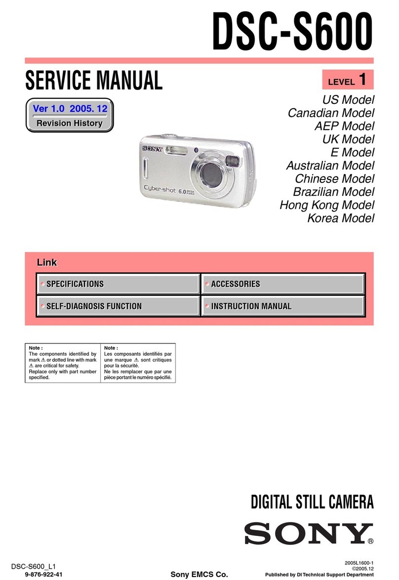
  9. Sony Cyber-shot DSC-S600 User manual

Sony Cyber-shot DSC-S600 User manual

US Model
Canadian Model
AEP Model
UK Model
E Model
Australian Model
Chinese Model
Brazilian Model
Hong Kong Model
Korea Model
SERVICE MANUAL
DIGITAL STILL CAMERA
LEVEL 2
Link
SERVICE NOTE
DISASSEMBLY
BLOCK DIAGRAMS
FRAME SCHEMATIC DIAGRAMS
SCHEMATIC DIAGRAMS
PRINTED WIRING BOARDS
REPAIR PARTS LIST
SPECIFICATIONS
SERVICE NOTE
DISASSEMBLY
BLOCK DIAGRAMS
FRAME SCHEMATIC DIAGRAMS
SCHEMATIC DIAGRAMS
PRINTED WIRING BOARDS
REPAIR PARTS LIST
SPECIFICATIONS
Link
Revision History
Revision History
Ver 1.0 2005. 12
How to use
Acrobat Reader
How to use
Acrobat Reader
Sony EMCS Co.
2005L1600 1
©2005.12
ublished by DI Technical Support Department
9-876-922-31
DSC S600_L2
DSC-S600
Internal memory
ON BOARD
Internal memory
ON BOARD
Note :
The components identified by
mark 0 or dotted line with mark
0 are critical for safety.
Replace only with part number
specified.
Note :
Les composants identifiés par
une marque 0 sont critiques
pour la sécurité.
Ne les remplacer que par une
pièce portant le numéro spécifié.
• Precaution on Replacing the SY 145 board
— 2 —
DSC S600_L2
S ECIFICATIONS
Camera
[S stem]
Image device 7.18 mm (1/2.5 type) color
CCD, Primary color filter
Total pixel number of camera
Approx. 6 183 000 pixels
Effective pixel number of camera
Approx. 6 003 000 pixels
Lens Carl Zeiss Vario-Tessar
3 zoom lens
f = 5.1 – 15.3 mm (31 – 93 mm
when converted to a 35 mm still
camera)
F2.8 – 5.1
Automatic ND filter switching
Exposure control Automatic exposure, Scene
Selection (7 modes)
White balance Automatic, Daylight, Cloudy,
Fluorescent, Incandescent
File format (DCF compliant)
Still images: Exif Ver. 2.21
JPEG compliant, DPOF
compatible
Movies: MPEG1 compliant
(Monaural)
Recording media Internal Memory (32 MB)
“Memory Stick Duo”
Flash Recommended distance (ISO
set to Auto): approx. 0.2 m to
7.0 m (7 7/8 inches to 275 5/8
inches) (W)/approx. 0.5 m to
3.8 m (19 3/4 inches to 149 5/8
inches) (T)
[Input and Output connectors]
USB jack mini-B
USB communication
Hi-Speed USB (USB 2.0
compliant)
[LCD screen]
LCD panel 5.1 cm (2.0 type) TFT drive
Total number of dots
84 960 (354×240) dots
[Power, general]
Power R6 (size AA) Alkaline batteries
(2), 3 V
HR 15/51:HR6 (size AA)
Nickel-Metal Hydride batteries
(2, not supplied), 2.4 V
ZR6 (size AA) Oxy Nickel
Primary Battery (2, not
supplied), 3 V
AC-LS5K AC Adaptor (not
supplied), 4.2 V
Power consumption
(during shooting with the LCD screen on)
1.0 W
Operating temperature
0°C to +40°C (+32°F to
+104°F)
Storage temperature
–20°C to +60°C (–4°F to
+140°F)
Dimensions 99.952. 0×36.8 mm
(4×2 1/8×1 1/2 inches)
(W/H/D, excluding protrusions)
Mass Approx. 181 g (6.4 oz)
(including two batteries and
wrist strap, etc.)
Microphone Electret condenser microphone
Speaker Dynamic speaker
Exif Print Compatible
PRINT Image Matching III
Compatible
PictBridge Compatible
Design and specifications are subject to change
without notice.
These specifications are extracted from instruction
manual of DSC S600 (2 658 425 11).
— 3 —
DSC S600_L2
1. Check the areaof your repairfor unsoldered orpoorly-soldered
connections. Checkthe entireboardsurfacefor soldersplashes
and bridges.
2. Check the interboard wiring to ensure that no wires are
"pinched" or contact high-wattage resistors.
3. Look for unauthorized replacement parts, particularly
transistors, that were installed during a previous repair. Point
them out to the customer and recommend their replacement.
4. Look for partswhich, throughfunctioning, showobvious signs
of deterioration. Point them out to the customer and
recommend their replacement.
5. Check the B+ voltage to see it is at the values specified.
6. Flexible Circuit Board Repairing
• Keep the temperature of the soldering iron around 270˚C
during repairing.
• Do not touch the soldering iron on the same conductor of the
circuit board (within 3 times).
• Be careful not to apply force on the conductor when soldering
or unsoldering.
Unleaded solder
Boards requiring use of unleaded solder are printed with the lead-
free mark (LF) indicating the solder contains no lead.
(Caution: Some printed circuit boards may not come printed with
the lead free mark due to their particular size.)
: LEAD FREE MARK
Unleaded solder has the following characteristics.
• Unleaded solder melts at a temperature about 40°C higher than
ordinary solder.
Ordinary soldering irons can be used but the iron tip has to be
applied to the solder joint for a slightly longer time.
Soldering irons using a temperature regulator should be set to
about 350°C.
Caution: The printed pattern (copper foil) may peel away if the
heated tip is applied for too long, so be careful!
• Strong viscosity
Unleaded solder is more viscous (sticky, less prone to flow) than
ordinary solder so use caution not to let solder bridges occur such
as on IC pins, etc.
• Usable with ordinary solder
It is best to use only unleaded solder but unleaded solder may
also be added to ordinary solder.
SAFETY CHECK-OUT
After correcting the original service problem, perform the following
safety checks before releasing the set to the customer.
SAFETY-RELATED COM ONENT WARNING!!
COM ONENTS IDENTIFIED BY MARK 0 OR DOTTED LINE WITH
MARK 0 ON THE SCHEMATIC DIAGRAMS AND IN THE ARTS
LIST ARE CRITICAL TO SAFE O ERATION. RE LACE THESE
COM ONENTS WITH SONY ARTS WHOSE ART NUMBERS
A EAR AS SHOWN IN THIS MANUAL OR IN SU LEMENTS
UBLISHED BY SONY.
ATTENTION AU COM OSANT AYANT RA ORT
À LA SÉCURITÉ!
LES COM OSANTS IDENTIFÉS AR UNE MARQUE 0 SUR LES
DIAGRAMMES SCHÉMATIQUES ET LA LISTE DES IÈCES SONT
CRITIQUES OUR LA SÉCURITÉ DE FONCTIONNEMENT. NE
REM LACER CES COM OSANTS QUE AR DES IÈSES SONY
DONT LES NUMÉROS SONT DONNÉS DANS CE MANUEL OU
DANS LES SU ÉMENTS UBLIÉS AR SONY.
CAUTION :
Danger of explosion if battery is incorrectly replaced.
Replace only with the same or equivalent type.
— 4 —
DSC S600_L2
TABLE OF CONTENTS
1. SERVICE NOTE
1-1. DESCRIPTION ON SELF-DIAGNOSIS DISPLAY······1-1
1-2. METHOD FOR COPYING OR ERASING THE DATA IN
INTERNAL MEMORY ··················································1-2
1-3. PRECAUTION ON REPLACING THE SY-145
BOARD ···········································································1-3
1-4. INITIAL LANGUAGE DATA CHECK··························1-3
1-5. HOW TO OPERATE THE CAMERA WITHOUT THE
FRONT CABINET ··························································1-3
2. DISASSEMBLY
2-1. DISASSEMBLY······························································2-3
3. BLOCK DIAGRAMS
3-1. OVERALL BLOCK DIAGRAM ····································3-1
3-2. POWER BLOCK DIAGRAM·········································3-3
4. RINTED WIRING BOARDS AND
SCHEMATIC DIAGRAMS
4-1. FRAME SCHEMATIC DIAGRAM································4-1
4-2. SCHEMATIC DIAGRAMS ············································4-5
4-3. PRINTED WIRING BOARDS ·····································4-27
4-5. MOUNTED PARTS LOCATION ·································4-36
5. RE AIR ARTS LIST
5-1. EXPLODED VIEWS ······················································5-3
5-2. ELECTRICAL PARTS LIST ··········································5-6
1 1
DSC S600_L2
1. SERVICE NOTE
Self-diagnosis display
• C: ss: ss
You can reverse the camera
malfunction yourself. (However,
contact your Sony dealer or local
authorized Sony service facility
when you cannot recover from the
camera malfunction.)
• E: ss: ss
Contact your Sony dealer or local
authorized Sony service facility.
1-1. DESCRI TION ON SELF-DIAGNOSIS DIS LAY
Display Code
C:32:ss
C:13:ss
Countermeasure
Turn the power off and on again.
Cause
Trouble with hardware.
Caution Display During Error
SYSTEM ERROR
FORMAT ERROR
MEMORY STICK ERROR
E:61:ss
E:91:ss
E:92:ss
Turn the power off and on again. Trouble with internal memory. INTERNAL MEMORY ERROR
Checking of lens drive circuit. When failed in the focus and zoom
initialization. —
Checking of flash unit or replacement
of flash unit.
Insert batteries correctly.
Abnormality when flash is being
charged.
Batteries are not inserted correctly.
Format the “Memory Stick Duo” or
internal memory. “Memory Stick Duo” or internal memory is
unformatted.
Insert a new “Memory Stick Duo”. “Memory Stick Duo” is broken.
1 2
DSC S600_L2
Copies all images in the internal memory to a “Memory Stick Duo”.
1Insert a “Memory Stick Duo” having 32 MB or larger capacity.
2Select [OK] with von the control button, then press z.
The message “All data in internal memory will be copied Ready?” appears.
3Select [OK] with v, then press z.
Copying starts.
Use batteries with enough capacity or the AC Adaptor (not supplied). If you attempt to copy image files
using batteries with little remaining capacity, the batteries may run out, causing copying to fail or possibly
corrupting the data.
You cannot copy individual images.
The original images in the internal memory are retained even after copying. To delete the contents of the
internal memory, remove the “Memory Stick Duo” after copying, then execute the [Format] command in
(Internal Memory Tool) (page 46).
You cannot select a folder copied on a “Memory Stick Duo”.
Even if you copy data, a (Print order) mark is not copied.
Cop
OK
See the following procedure.
Cancel
Cancels the copying.
This item does not appear when a “Memory Stick Duo” is inserted in the camera.
The default settings are marked with .
Formats the internal memory.
• Note that formatting irrevocably erases all data in the internal memory, including even protected images.
1Select [OK] with von the control button, then press z.
The message “All data in internal memory will be erased Ready?” appears.
2Select [OK] with v, then press z.
The format is complete.
Format
OK
See the following procedure.
Cancel
Cancels the formatting.
1-2. METHOD FOR CO YING OR ERASING THE DATA IN INTERNAL MEMORY
The data can be copied/erased by the operations on the Setup screen. (When erasing the data, execute formatting the internal memory.)
Note1: When replacing the SY-145 board, erase the data in internal memory of the board before replacement.
Note2: When replacing the SY-145 board or the IC203 on the SY-145 board, execute formatting and initialize the internal memory after replacement.
Method for Copying the Data in Internal Memory
Method for Formatting the Internal Memory
1 3E
DSC S600_L2
1-5. HOW TO O ERATE THE CAMERA WITHOUT THE FRONT CABINET
Cabinet (front) assembly
LB 117 board
Remove the claw
LB 117 board
S101 switch
(Lens barrier open)
SW 461 board
Adhesive tape
solder the leads
Remove the LB-117 board from the cabinet (front) asembly, solder the leads to the SW-461 board, and fix the S101 switch (Lens barrier
open) to the ON position with an adhesive tape.
1-3. RECAUTION ON RE LACING THE SY-145 BOARD
• The Repair Board has already been adjusted. Re-initialization or EVR data copy from the set before repair is not required.
• Perform “Initial Language Data Check” mentioned below, and also the adjustment items necessary after SY Board replacement.
1-4. INITIAL LANGUAGE DATA CHECK
If the SY-145 board was replaced, initial language setting may be changed. Accordingly, change the following data so as to set same initial
language as that of the set distributing in each region.
Initial language: Language displayed at the next starting if the setting of Setup menu was reset.
It is different from the language setting selectable with the menu.
Initial Language Data
Note: GP2 is fixed to English.
GP3 is either English, Spanish, or Russian.
GP4 is either English, Spanish, Portugal, Simplified Chinese, or Korean.
Writing Method:
1) Select page: 00, address: 01 and set data: 01.
2) Select page: 4F, address: 8C, and set the Initial Language Data.
3) Select page: 40, address: 38, and set data: 00.
4) Click [Save] on the SEUS screen.
5) Select page: 80, address: 34, and check that the data is “00”.
6) Select page: 80, address: 30, and check that the data is “00”.
7) Select page: 00, address: 01, and set data: 00.
8) Turn off the camera.
9) Turn on the camera. Execute “Initialize” of Setup screen.
10) Check the language displayed when the camera starts.
Page Address Data Language GP2 GP3 GP4
4F 8C
00 English zzz
04 Spanish zz
06 Portugal z
08 Simplified Chinese z
0B Russian z
0D Korean z
DSC S600_L2
Link
Link
2. DISASSEMBLY
HELP
DISASSEMBLY
DISASSEMBLY
HELP
COMMON NOTE FOR DISASSEMBLY
2 1
2. DISASSEMBLY
2. DISASSEMBLY
DSC S600_L2
2. DISASSEMBLY
NOTE FOR RE AIR
DISCHARGING OF THE FLASHLIGHT OWER SU LY CA ACITOR
The charging elect capacitor 180uF (330V) is charged up to the
maximum 300 V potential.
There is a danger of electric shock by this high voltage when the
capacitor is handled by hand. The electric shock is caused by the
charged voltage which is kept without discharging when the main
power of the DSC-S600 is simply turned off. Therefore, the
remaining voltage must be discharged as described below.
reparing the Short Jig
To preparing the short jig. a small clip is attached to each end of
a resistor of 1 kW /1 W (1-215-869-11)
Wrap insulating tape fully around the leads of the resistor to
prevent electrical shock.
1 kΩ/1 W
Wrap insulating tape.
Make sure that the flat cable and flexible board are not cracked of
bent at the terminal.
Do not insert the cable insufficiently nor crookedly.
Cut and remove the part of gilt
which comes off at the point.
(Take care that there are
some pieces of gilt left inside)
hen remove a connector, don't pull at wire of connector.
Be in danger of the snapping of a wire.
hen installing a connector, don't press down at wire of connector.
Be in danger of the snapping of a wire.
Discharging the Capacitor
Short circuits between the positive and the negative terminals of
charged capacitor with the short jig about 10 seconds.
SY 145
Shorting jig
(1k
Ω
/ 1W)
Capacitor
DSC S600_L2
2 3 2 4
2-1. DISASSEMBLY
The following flow chart shows the disassembly procedure.
2. DISASSEMBLY
2. DISASSEMBLY
2. DISASSEMBLY
SY 145
SY 145
SY 145
SY 145
5
7
6
2
3
4
1
2
3
5
1
8
4
3
2
1
1
Slide the BT cover.
2
Screw (M1.7x4)
3
Open the USB cover.
4
Screw (M1.7x4)
5
Screw (M1.7x4)
6
Screw (M1.7x4)
7
Open the cabinet (upper) assembly.
8
Cabinet (rear) assembly
1
Three solderings
2
Two solderings
3
Open the BT cover.
4
Open the cabinet (upper) assembly.
5
Cabinet (front) assembly
1
Two solderings
2
Flexible board (from the LCD unit)
3
LCD unit
1
Two solderings
2
Claw
3
Two claws
4
Flexible board (from the lens block assembly)
5
Flexible board (from the lens block assembly)
6
Flexible flat cable (FFC 058)
7
Flexible flat cable (FFC 056)
8
SY 145 board, RL 063 board,
speaker, microphone, etc.
1
4
3
2
1
Screw (M1.7x4)
2
Two claws
3
RL 063 board
4
Cabinet (upper) assembly
1
2
8
3
5
6
4
A
(See page 2 5)
C
(See page 2 5)
B
(See page 2 5)
7
Refer to page 2 1 "DISCHARGING OF
THE FLASHLIGHT POWER SUPPLY
CAPACITOR (LND904, LND905)",
when discharging the capacitor.
HELP 02
HELP 01
HELP 03
HELP 04
DSC S600_L2
2. DISASSEMBLY
2. DISASSEMBLY
2 5 2 6E
SY 145
SY 145
SY 145
SY 145
A
C
B
3
1
4
1
5
1
Flexible flat cable (FFC 058)
2
Flexible board (from the optical unit)
3
Screw (M1.7x4)
4
LCD frame
5
SW 461 board, flexible flat cable (FFC 058)
1
Two solderings
2
Speaker holder
3
Speaker
4
Two solderings
5
Miclophone holder
6
Miclophone
HN 015
1
Two solderings
2
Elect 180uF (330V) capacitor
3
Three solderings
4
Flash unit, harness (HN 015)
5
SY 145 board, RL 063 board,
flexible flat cable (FFC 056), etc.
4
1
2
3
1
2
4
5
2
4
1
Flexible board (from the lens block assembly)
2
Flexible board (from the lens block assembly)
3
Flexible board (from the optical unit)
4
Lens block assembly, optical unit.
3
2
HELP 05
HELP 06
3
5
6
RL 063 SW 461
DSC S600_L2
HEL
HEL
Disassembling and assembling procedures that require attention are described here.
Mode Switch of
the SW 461 board
Cabinet (rear) assembly
HELP 01
When installing the Cabinet (Rear) assembly, install it while aligning the
Mode switch of the SW 461 board with the position A of the Cabinet (Rear) assembly.
A
Yellow
Two reads
(from the BM 001 board)
Tree reads
(from the LB 117 board)
Red
SW 461 board
Black
Gray
White
HELP 02
Solder each lead according to the color (Y: yellow, G: gray, W: white, R: red, B: black) displayed on the SW 461 board.
DSC S600_L2
HEL
SY 145
When installing the cabinet (front) asembly,
put the lead lines in the space between
the tripod screw and the SW 461 board.
When installing the cabinet (front) asembly,
put the lead lines in the space between the
optical unit and the DC mortor.
HELP 03
SW 461 board
Tripod screw
DC mortor
Optical unit
Solder each lead according to the color (R: red, B: black) displayed on the SY 145 board.
Black
Red
LCD leads
SY 145 board
HELP 04
DSC S600_L2
HEL
HELP 05
Black Red
SY 145 board
Speaker
Mic unit
Solder each lead according to the color (R: red, B: black) displayed on the SY 145 board.
HELP 06
Give folding to the flexible flat cable (FFC 057).
SY 145 board
SY 145 board
RL 063 board
Peak folding
Peak folding
Valley folding
Valley folding
RL 063 board
Flexible flat cable
(FFC 057)
Flexible flat cable
(FFC 057)
DSC S600_L2
Link
Link
3. BLOCK DIAGRAMS
OVERALL BLOCK DIAGRAM POWER BLOCK DIAGRAM
DSC S600_L2
3 1 3 2
3-1. OVERALL BLOCK DIAGRAM
3. BLOCK DIAGRAMS
( ) : Number in parenthesis ( ) indicates the division number of schematic diagram where the component is located.
IC101
CAMERA DSP
SYSTEM CONTROL
IC301
TIMING
GENERATOR
S/H
A/D CONV.
CCD IMAGER
IC601
MIC AMP
SPEAKER AMP
77
0
37
40
44
4
53
56
60
92
11,
16,12
9,91
5,6
,102
90,79,76
97,9 ,100,101
103,104,105,3
2,4,7,10,14,1
19
17
20
1
3
H1A,B
H2A,B
RG
V1A,B
V2
V3A,B
V4
V5A,B
V6
V7A,B
V VST
XMS IN
4,3,5,7,2,
6
CN002
CN1001
CN703
CN006
IRIS
SHUTER
C5
C6
B6
E1
F2
H5
J5
AC1
AD1
E9
B
F3
E3
A5
A2
B10 A4
CN301
X101
EXTAL
CCD OUT
CN301
LENS TEMP1
SENSOR LENS
TEMP1
LENS
TEMP2
CN401
CA AD0 - CA AD13
CLK TGO
CA HD CA FD
D23
R4
D9
E4
A6
C1
AF4
U4
F22
E22
L23
K23
L22
XACCESS LED
32-24,22,13-1133
E6
E5
MS D0-MS D3, MS BS, MS CLK MS D0-MS D3, MS BS, MS CLK
L26
K25
AA23
K26
DSP QCLK
MEMORY
STICK
Duo
CONNECTOR
LCD
BACK
LIGHT
B6
LENS UNIT
(LSV-951A)
CD-606 FLEXIBLE BOARD SY-145 BOARD SW-461 BOARD (2/3)
D003
(ACCESS)
SAN1 SO,XSAN1SCK
SO
SI
SCK
SO
SI
SCK
IC004,005
IC001
1
4
5
14
11
1
2
6
|
3
13,12,14,16,11,17
15
17
|
22
24
25
23
27
26
30
2.0 INCH
COLOR DIGITAL
LCD PANEL
LCD901
XSAN RST OUT
KEY AD0
KEY AD1
XAE LOCK SW
XSHUTTER SW
MODE DIAL 0
AUIN
E4
Y26
XCS_AUDIO
AUOUT
XPWR LED
XSTRB LED
XAE LOCK LED
OVF SENS
XPWR ON
XAF LED
BL H
BL L
STRB CHG
XSTRB FULL
STRB CHG CONT
STRB ON
SAN1 SO, XSAN1SCK
LCD CK
LCD HD
LCD VD
LCD D2-D7
BATTERY
HOLDER
A D4
A7
B7
C7
C9
OSC I
A9 OSC O
X001
32.76 KHz
F001
F002
A 2.9V
CAM 12V
EVER 3.1V
EVER 2.9V
D 3.2V
A 3.2V
MS VCC
CAM 2.9V
D 1. V
M 5V
D 1.2V
CAM -7.5V
BL H
BL L
ST UNREG
UNREG
BATT UNREG
BATT GND
BATT SENS
XDD RST OUT
XPWR ON
USB VBUS
XMS IN
VL 3V
XPWR OFF
BATT SENS
XDD RST OUT
XPWR OFF
2.9V/12V REG
B
9 93
DC/DC CONVERTER
REAL TIME CLOCK
AC4,AE4
AE5,AC5
AB6,AF6
E ,E7,D6
D5,E6,B4
K5,G4,H4,L5
H2,H1,J1,J2
M5,J4,K4,M6
K2,K1
N21
P23
U2
T2
R6
SAN1 SO, SI, SCK, XSAN1SCK
SAN1 SO, SI, SCK
12MHz
XTAL OSC
X102
33.75MHz
CLKTGEXT
XTAL OSC
AB5
AA5
Y5
SAN0 SO, SI, XSAN0SCK
FFC-056
(FLEXIBLE FLAT CABLE) (2/3)
(2/ )
(1/ )
(4/ )
(3/ )
(4/ ) (4/ )
(5/ )
(6/ )
(2/ )
( / )
( / )
1
2
ST UNREG
HIGH VOLTAGE
CHAGER
IGBT DRIVE
FLASH
DRIVE
C9001
MAIN
CAPACITOR
FLASH
UNIT
XENON
TUBE
( )
T901
Q901 XE K(L)
XE A(H)
D901
(RECT)
10
15
9
6
4 7
IC901
TRIGGER
COIL
FFC-057 (FLEXIBLE FLAT CABLE)
S202
POWER
S201
SHUTTER
D201 (POWER)
LED901
(AF LED)
XAF LED
RL-063 BOARD
7
6
2
3
FFC-056 (FLEXIBLE FLAT CABLE) (3/3)
S001, 004, 002, 005, 003
DOWN, RIGHT, UP, LEFT, SET
S011
D001 (FLASH)
D002 (AE LOCK)
MOVIE / STILL / PLAY
S007, 009, 00 , 010, 006
DISPLAY, DUST, MENU, ZOOM WIDE, ZOOM TELE
SW-461
BOARD
(3/3)
3,2
1
(USB)
CN003
BT001
LITHIUM
BATTERY
(SECONDARY)
CN006
VL 3V
USB VBUS
5
6
20
22
21
2
3
FFC-05 (FLEXIBLE FLAT CABLE)
OPTICAL
VIEWFINDER
UNIT
OVF RESET
SENSOR
OVF ZOOM
MOTOR
OVF SENS
M
CN001
4
|
1
7
SP901
SPEAKER
MIC901
MICROPHONE
MIC
MIC SIG
SP+
SP-
SAN1 SO, XSAN1SCK
D+, D-
USB DP, USB DM
IRIS EN
IRIS IN
IRIS DRIVE
FOCUS MOTOR DRIVE
ZOOM MOTOR DRIVE
LENS BARREIER
MOTOR DRIVE
HALL AMP
IC401
E1
F1
D1
C1
H3
C2
G3
B1
IRIS +
IRIS - B
C7
SAN LENSV OPEN
SAN LENSV CLOSE
LENSV OPEN
LENSV CLOSE
ZM SENS 2ND
ZM SENS 1ST
LENSV OPEN
LENSV CLOSE
H
D6
F7
G7
ZM EN
ZM DIR A
ZM DIR B
F
E
MSHUT EN
MSHUT DIR
SHUTTER DRIVE
OVF ZOOM DRIVE
IC402
B3
B4
D1
B1
FOCUS +
FOCUS -
ZOOM A
ZOOM XA
ZOOM B
ZOOM XB
F2
F3
E6
D6
B5
B6
C6
C5
H1
F2
HALL +
HALL - A5
A
SHUTTER+
SHUTTER-
OVF EN
OVF DIR A
OVF DIR B
F5
G4
G6
SAN1 SO, SI, XSAN1SCK
XSAN RST OUT
SAN 27M CLK0
H6
F4
FFC-056
(FLEXIBLE FLAT CABLE) (1/3)
SW-461
BOARD
(1/3)
BM-001
BOARD
LB-117 BOARD
M001
LENS BARRIER
MOTOR
XLENSV
OPEN SENS
XLENSV
CLOSE SENS
M
S101
LENS BARRIER
OPEN
( )
( )
S102
LENS BARRIER
CLOSE
26
25
CN006
24
23
IRIS MOTOR
ZOOM RESET
SENSOR1
ZOOM RESET
SENSOR2
M
23
22
20
19
26
33
1
15
FOCUS MOTOR
M
ZOOM MOTOR
M
5
3
24
12
10
14
21
SHUTTER MOTOR
M
H
OVF A
OVF B
OVF XA
OVF XB
OVF A
OVF B
OVF XA
OVF XB
IC203
SUPER AND
FLASH MEMORY
IC201
BURST
FLASH MEMORY
CPU_D0-D15
D0-D15 D0-D15
A1-A21
CPU_A1-A21,A25
A20,A21,A25
AB13,AA13,AE13,AF13,
AF12,AE12,AA12,AC12,AC11,
AB12,AE11,AF11,AE10,AB11,
AC10,AB10
AF21,AF20,AE20,AB1 ,AB19,
AC19,AB16,AE19,AF19,AF1 ,
AE1 ,AA15,AC1 ,AC17,AB15,
AE17,AF17,AE16,AB14,AC16,
AC15,AE14
IC202
256Mbit
SDRAM
D21,D22,D20,B22,A22,A23,
B23,E20,E21,B24,A24,A25,
B25,C25,C26,B26,E10,A10,
D10,E11,B10,A11,B11,E12,
D11,D12,F12,B12,A12,E13,
D13,D14
D17,D1 ,D16,B1 ,A19,
B19,E16,D19,E19,E17,
B20,A20,E1
D0-D31
A0-A12
IRIS EN
IRIS IN N4
P4
ZM SENS 1ST
ZM SENS 2ND V4
U5
SAN LENSV OPEN
SAN LENSV CLOSE
LENS TEMP1
LENS TEMP2
J25
K22
XLENSV OPEN SENSE
XLENSV CLOSE SENSE
Y22
AC23
ZM EN
ZM DIR A
ZM DIR B
MSHUT EN
MSHUT DIR R5
R25
R26
Y4
AC14
AA14
N2
N6
M2
L4
L2
N5
SAN 27M CLKO AF9
A1
OVF EN
OVF DIR A
OVF DIR B
R22
V23
AB22
OVF A
OVF B
OVF XA
OVF XB
CCD IMAGER and CD-606 FLEXIBLE BOARD are included in the LENS BLOCK ASSY (A-1156- 57-A).
DSC S600_L2
3 3 3 4E
3-2. OWER BLOCK DIAGRAM ( ) : Number in parenthesis ( ) indicates the division number of schematic diagram where the component is located.
E10
LX3
E9VO3
LV3
RS3
G9BG4
TG4
F10
PSG4 G
D002
(RECT)
D003
(RECT)
L005
BL H
BL H
BL L
F9
F
BL L
-7.5V ON
-7.5V
54
21
3
1
4
5
2
3
-7.5V ON
M 5V M 5V
D 3.2V
A 2.9V, D 1. V, D 1.2V, MS VCC
D 1.2V
CAM 12V
PANEL 15V
PANEL 15V
Q1002
D1002
CAM 15V CD
CCD IMAGER and CD-606 FLEXIBLE BOARD
are included in the LENS BLOCK ASSY (A-1156- 57-A).
D 3.2V
M5V
D 3.2V
D 1. V
A 2.9V
D 3.2V
D 3.2V
D 3.2V
D 3.2V
D 1. V
Q005, 006
15V
A 2.9V
MS VCC
CAM 2.9V
CAM -7.5V CAM -7.5V CD
ZM RST1 VCC
ZM RST2 VCC
L00
Q001
SWITCHING
Q003
SWITCH
Q002
RECT
MS PWR IN
MS PWR
G1
G2
PWR56 OUT
UNREG2
LDO2
LDO1
RTC BAT
UNREG1-1,2
LDO2IN
C10
LX2
D
VFB2
D10
PWR2
H9VFB5
B
B3
A3
F7VFB4
L003
L006
L301
R402
CN401
CN1001
CN301
R401
L201
VO1-1
VO1-2
H2
VFB1
PWR1-1
PWR1-2
PWR1-3
LX5-1
LX5-2
LX5-3
LX5-4
J9
J10
K9
K10
XCS DD
SAN0 SO
SAN0 SI
XSAN0 SCK
XCS DD
SAN0 SO
SAN0 SI
XSAN0 SCK
A6
C5
C6
B6
J7
K7
J6
K6
F1
F2
J1
K1
R26
Y4
3
4
1
IC004
2.9V REG
1
3
5
IC005
12V REG
CCD IMAGER
IC402
SHUTTER DRIVE
OVF ZOOM DRIVE
M 5V
IC601
MIC AMP
SPEAKER AMP
IC401
IRIS DRIVE
FOCUS MOTOR DRIVE
ZOOM MOTOR DRIVE
IC301
S/H
A/D CONV.
TIMING GENERATOR
1. V REG
LDO3
LDO3IN
VL 3V
R041
EVER 2. V
B7
XPWR OFF XPWR OFF
C7
XPWR ON
XPWR ON XPWRON1
D3
MS PWR ON MS PWR ON
BATT SENS D4 DTG1
XDD RST OUT A7
K25
AA23
T25
XRESET
B2
A2
2.9V REG
A1
B1
C2
L002
3.1V REG
IC001
DC/DC CONVERTER
REAL TIME CLOCK
A OSC I
A9 OSC O
X001
32.76 KHz
IC101
CAMERA DSP
SYSTEM CONTROL
IC202
256Mbit
SDRAM
W23
AB5
AA5
Y5
IC201
BURST
FLASH MEMORY
IC203
SUPER AND
FLASH MEMORY
P25
AB22
-7.5V ON
SY-145 BOARD
RL-063
BOARD
SW-461
BOARD
BATTERY
HOLDER
D001
R002
F001
F002 UNREG
ST UNREG ST UNREG
BATT UNREG
BATT GND
CN703
CN006
CN001
R22
V23
STRB CHG
XSTRB FULL
STRB CHG CONT
STRB CHG
XSTRB FULL
STRB CHG CONT
D 3.2V
A 2.9V
D 1.2V
D 1. V
D 3.2V
D 3.2V
9MS VCC
D 3.2V
D 3.2V
SD 1. V
POWER
S202
A4
XAF LED
XAF LED
D23
E22
XPWR LED
XPWR LED
XSTRB LED
XSTRB LED
D201 (POWER)
RST VCC
D001 (FLASH)
LED901
(AF LED)
VL 3V
BT001
LITHIUM
BATTERY
(SECONDARY)
CD-606
FLEXIBLE BOARD
ZOOM
RESET2
SENSOR
ZOOM
RESET1
SENSOR
LENS UNIT
(LSV-951A)
13
1
5
9
2
1
9
6
F003
Q004
SWITCHING & RECT
H7VFB6
H6GT6 L009
FFC-05
(FLEXIBLE FLAT CABLE)
FFC-057
(FLEXIBLE FLAT CABLE)
FFC-056
(FLEXIBLE FLAT CABLE)
OPTICAL
VIEWFINDER
UNIT
R009
CN002
MEMORY
STICK
Duo
CONNECTOR
3
4
2
L901
1
2
HIGH VOLTAGE
CHAGER
IGBT DRIVE
T901
XE A(H)
D901
(RECT)
15
10
9
6
3
IC901
C9001
MAIN
CAPACITOR
VCC1
VGH
VDD
LCD
BACK LIGHT
2.0 INCH
COLOR DIGITAL
LCD PANEL
LCD901
9
10
11
L1002
L1001
D 3.2V
DETECT
Q1001
OVF RESET
SENSOR
( / ) ( / )
( / )
(5/ )
(6/ )
(1/ )
(2/ )
(2/ )
(3/ )
(4/ )
(4/ )
(4/ )
FLASH
UNIT
XENON
TUBE
( )
H1
DSC S600_L2
4 1
4-1. FRAME SCHEMATIC DIAGRAM
4. RINTED WIRING BOARDS AND SCHEMATIC DIAGRAMS
4 2 FRAME SCHEMATIC DIAGRAM
LND90
TRIGGER
33PCN1001
1
2
3
4
5
6
7
9
10
11
12
13
14
15
16
17
1
19
20
21
22
23
24
25
26
27
2
29
30
31
32
33
10PCN703
1
2
3
4
5
6
7
9
10
LND905
LND601
LND403
CN006 26P
1
2
3
4
5
6
7
9
10
11
12
13
14
15
16
17
1
19
20
21
22
23
24
25
26
33PCN301
1CAM-7.5V-CD
2REG_GND
3RG
4REG_GND
5CAM15.0V-CD
6POWER_SAVE
7REG_GND
CCD_OUT
9CCD_GND
10REG_GND
11V
12V7B
13V7A
14VSUB_CONT
15SHT
16REG_GND
17H1B
1H2B
19H1A
20H2A
21REG_GND
22V6
23VHLD
24V5B
25V5A
26V4
27VST
2V3B
29V3A
30V2
31V1B
32V1A
33TH2
CN003
1
VCC
2
D-
3
D+
4ID
5
GND
CN001 P
7
6
5
4
3
2
1
LND004
LND002
BATT_GND
LND03
LND602
CN002
1
2
3
4
5
6
7
9
10
LND401
LND402
LND101
LND102
LND103
LND003
LND906
XE_A(H)
LND907
XE_K(L)
LND604
26
1
2
3
4
5
6
7
9
10
11
12
13
14
15
16
17
1
19
20
21
22
23
24
25
26
M001
LND040
33PCN401
1
2
3
4
5
6
7
9
10
11
12
13
14
15
16
17
1
19
20
21
22
23
24
25
26
27
2
29
30
31
32
33
LND039
LND404
LND041
LND904
LND037
LND603
LND001
BATT_UNREG
10P
1
2
3
4
5
6
7
9
10
9P
1
2
3
4
5
6
7
9
9P
1
2
3
4
5
6
7
9
1
A
XMS_IN
PT_E/LED_K1
VCC1
XSCK
XACCESS_LED
SI
D2
MS_D3
MS_D1
VL_3V
XACCESS_LED
ZM_RST2_VCC
KEY_AD0
COMOUT
RST_VCC
VVCOM
REG_GND
D1
ZM_OVF_XB
ZOOM_A
REG_GND
KEY_AD1
VSH
VCC
D-
MODE_DIAL0
MS_CLK
DATA2
ZM_OVF_XA
LCD BACK LIGHT
(Included in the LCD901)
DCK
BIAS+
MS_VCC
MIC
KEY_AD1
BLON
SHUTTER-
D+
XOVF_RST_LED
GND2
COMDC
ZOOM_XA
PT_E/LED_K2
KEY_AD0
MAIN CON-
ZOOM_XB
ZOOM_A
ND-
HALL-
VCC
VGL
XAE_LOCK_LED
ZM_OVF_B
ZM_OVF_XB
XLENSV_CLOSE_SENSE
VL_3V
XVD
ZOOM_XA
MIC_SIG
BL_L
BIAS-
VCOM
MS_CLK
VBC
XRESET
C2+
FOCUS-
XSTRB_LED
MS_D2
VCC
ND+
D5
MS_BS
XLENSV_OPEN_SENSE
OVF_SENS
MIC_GND
N.C.
REG_GND
LENSV_OPEN
MS_D1
NC
ZOOM_XB
XLENSV_OPEN_SENSE
XLENSV_CLOSE_SENSE
D4
INT
LENSV_CLOSE
REG_GND
XLENSV_CLOSE_SENSE
XLENSV_OPEN_SENSE
REG_GND
BL_H
GND
VSS
EMITTER
MAIN CON+
DATA1
ZM_OVF_XA
GND
N.C.
MS_D2
N.C.
REG_GND
REG_GND
SCLK
GND
D3
LENSV_CLOSE
SHUTTER-
SP-
LCD901
2.0 INCH
COLOR DIGITAL LCD PANEL
XHD
BS
LENSV_OPEN
TH1
XMS_IN
GND
D+
LENSV_CLOSE
EMITTER
OVF_SENS
ZM_OVF_A
FFC-057
N.C.
MODE_DIAL0
ZOOM_B
VGH
MS_VCC
LENSV_CLOSE
RST_VCC
ND+
SHUTTER+
ZM_SENS_OUT2
TEST
NC
ND-
SDIO/DATA0
OPTICAL
VIEW FINDER
UNIT
ZM_RST1_VCC
MS_BS
ZM_OVF_B
XLENSV_OPEN_SENSE
NC
D0
ZM_OVF_A
ZM_OVF_XB
ZM_OVF_XA
XAE_LOCK_LED
XSTRB_LED
OVF_SENS
EMITTER
N.C.
RST_VCC
ZM_OVF_B
ZM_OVF_A
D-
MS_D0
LENSV_OPEN
HALL+
SP+ FOCUS+
LENSV_OPEN
GND
LENSV_OPEN
LENSV_CLOSE
C2-
ZM_SENS_OUT1
SHUTTER+
XLENSV_CLOSE_SENSE
VSS
VDD
DATA3
D_3.2V
ZOOM_B
GND
MS_D3
XCS
N.C.
REG_GND
D_3.2V
MS_D0
XSHUTTER_SW
N.C.
XAE_LOCK_SW
XPWR_ON
D_3.2V
N.C.
REG_GND
XPWR_LED
XAF_LED
BL_H
BL_L
CCD IMAGER
(6M)
CD-606
FLEXIBLE
BOARD
LENS ASSY
XSHUTTER_SW
N.C.
D_3.2V
XPWR_LED
XAE_LOCK_SW
N.C.
XAF_LED
XPWR_ON
REG_GND
FLEXIBLE
FLAT CABLE
RL-063 BOARD
BATTERY
HOLDER
C9001
SP901
SPEAKER
HN-007 HARNESS
HN-006 HARNESS
HN-009 HARNESS
HN-00 HARNESS
MIC901
MICROPHONE
HN-011 HARNESS
HN-010 HARNESS
BM-001 BOARD
LB-117 BOARD
HN-012 HARNESS
HN-013 HARNESS
HN-014 HARNESS
FLEXIBLE
FLAT CABLE
FFC-05FFC-056
FLEXIBLE
FLAT CABLE
HN-015 HARNESS
(FLASH)
(CAPACITOR)
SW-461 BOARD
LENS
BARRIER
MOTOR
BT001
LITHIUM
BATTERY
(SECONDARY)
MEMORY
STICK Duo
CONNECTOR
USB
E
I
J
K
D
G
H
C
O
N
F
M
L
B
154
16
121152 1413103679 16
(1/ )CAMERA A/D CONV.TIMING GENERATOR
(2/ )LENS DRIVE
(3/ )CAMERA DSP,SYSTEM CONTROL
(4/ )SUPER AND,FLASH MEMORY,SDRAM
(5/ )ADUIO AMP,MIC,SP
(6/ )FLASH DRIVE
(7/ )LCD PANEL,CONNECTOR
( / )DC/DC CONVERTER
SY-145 BOARD
CCD IMAGER and CD-606 FLEXIBLE BOARD are
included in the LENS BLOCK ASSY(A-1156- 57-A).
and it is not supplied as an independent
service parts.
LB-117 BOARD (OPEN/CLOSE SWITCH)
BM-001 BOARD (LENS OPEN/CLOSE MOTOR) RL-063 BOARD
(POWER SWITCH)
SW-461 BOARD
(JACK, FUNCTION SW, LITHIUM BATTERY)
LB-117 BOARD (OPEN/CLOSE SWITCH) SW-461 BOARD
(JACK, FUNCTION SW, LITHIUM BATTERY)
BM-001 BOARD (LENS OPEN/CLOSE MOTOR) RL-063 BOARD
(POWER SWITCH)
COMMON NOTE FOR SCHEMATIC DIAGRAMS
4-2. SCHEMATIC DIAGRAMS
Link
Link
DSC S600_L2
DSC S600_L2
4 3
4-2. SCHEMATIC DIAGRAMS
Link
(For schematic diagrams)
• All capacitors are in µF unless otherwise noted. pF : µ
µF. 50 V or less are not indicated except for electrolytics
and tantalums.
• Chip resistors are 1/10 W unless otherwise noted.
kΩ=1000 Ω, MΩ=1000 kΩ.
• Caution when replacing chip parts.
New parts must be attached after removal of chip.
Be careful not to heat the minus side of tantalum
capacitor, Because it is damaged by the heat.
• Some chip part will be indicated as follows.
Example C541 L452
22U 10UH
TA A2520
• Constants of resistors, capacitors, ICs and etc with XX
indicate that they are not used.
In such cases, the unused circuits may be indicated.
• Parts with * differ according to the model/destination.
Refer to the mount table for each function.
• All variable and adjustable resistors have characteristic
curve B, unless otherwise noted.
• Signal name
XEDIT → EDIT PB/XREC → PB/REC
•2: non flammable resistor
•5: fusible resistor
•C: panel designation
•A: B+ Line
•B: B– Line
•J: IN/OUT direction of (+,–) B LINE.
•C: adjustment for repair.
• Circled numbers refer to waveforms.
(Measuring conditions voltage and waveform)
• Voltages and waveforms are measured between the
measurement points and ground when camera shoots
color bar chart of pattern box. They are reference values
and reference waveforms.
(VOM of DC 10 MΩ input impedance is used)
• Voltage values change depending upon input
impedance of VOM used.)
recautions for Replacement of imager
• If the imager has been replaced, carry out all the
adjustments for the camera section.
• As the imager may be damaged by static electricity from
its structure, handle it carefully like for the MOS IC.
In addition, ensure that the receiver is not covered with
dusts nor exposed to strong light.
1. Connection
2. Adjust the distance so that the output waveform of
Fig. a and the Fig. b can be obtain.
When indicating parts by reference number, please
include the board name.
THIS NOTE IS COMMON FOR SCHEMATIC DIAGRAMS
(In addition to this, the necessary note is printed in each block)
Kinds of capacitor
Temperature characteristics
External dimensions (mm)
Yellow
AABBA=B
Fig. a (Video output terminal output waveform)
Electronic beam
scanning frame
CRT picture frame
H
Cyan
Green
White
Magenta
Red
Blue
Fig.b (Picture on monitor TV)
Note :
The components identified by
mark 0 or dotted line with mark
0 are critical for safety.
Replace only with part number
specified.
Note :
Les composants identifiés par
une marque 0 sont critiques
pour la sécurité.
Ne les remplacer que par une
pièce portant le numéro spécifié.
Pattern box Front of the lens
L = 1 m (PTB 450)
L = 40 cm (PTB 1450)
LCamera
Pattern box PTB-450
J-6082-200-A
or
Small pattern box
PTB-1450
J-6082-557-A
For PTB-450:
J-6020-250-A
For PTB-1450:
J-6082-559-A
Pattern box Color bar chart
4-2. SCHEMATIC DIAGRAMS

Other manuals for Cyber-shot DSC-S600

77

Other Sony Digital Camera manuals

Sony DSC-H300 User manual

Sony

Sony DSC-H300 User manual

Sony DSC-RX0M2 Reference guide

Sony

Sony DSC-RX0M2 Reference guide

Sony Cybershot,cyber-shot dsc-w570 User manual

Sony

Sony Cybershot,cyber-shot dsc-w570 User manual

Sony BRC-X400 User manual

Sony

Sony BRC-X400 User manual

Sony DSC-TX5 Cyber-shot® User manual

Sony

Sony DSC-TX5 Cyber-shot® User manual

Sony DSLR-A700K - alpha; Digital Single Lens Reflex... User manual

Sony

Sony DSLR-A700K - alpha; Digital Single Lens Reflex... User manual

Sony Cyber-shot DSC-W200 User manual

Sony

Sony Cyber-shot DSC-W200 User manual

Sony Cyber-shot DSC-WX7 User manual

Sony

Sony Cyber-shot DSC-WX7 User manual

Sony PCS-DS150 User manual

Sony

Sony PCS-DS150 User manual

Sony Cyber-shot DSC-S600 User manual

Sony

Sony Cyber-shot DSC-S600 User manual

Sony DSC-W310 User manual

Sony

Sony DSC-W310 User manual

Sony Cyber-shot DSC-U20 User manual

Sony

Sony Cyber-shot DSC-U20 User manual

Sony DSC-G1 - Cyber-shot Digital Camera User manual

Sony

Sony DSC-G1 - Cyber-shot Digital Camera User manual

Sony ILCE-QX1 Operating instructions

Sony

Sony ILCE-QX1 Operating instructions

Sony Cyber-shot DSC-HX30 User manual

Sony

Sony Cyber-shot DSC-HX30 User manual

Sony Cyber-shot DSC-TX20 User manual

Sony

Sony Cyber-shot DSC-TX20 User manual

Sony FX3 User manual

Sony

Sony FX3 User manual

Sony CYBER-SHOT DSC-F717 User manual

Sony

Sony CYBER-SHOT DSC-F717 User manual

Sony DSC S730 - Cyber-shot Digital Camera User manual

Sony

Sony DSC S730 - Cyber-shot Digital Camera User manual

Sony Cyber-shot DSC-S600 User manual

Sony

Sony Cyber-shot DSC-S600 User manual

Sony ZV-1M2 User guide

Sony

Sony ZV-1M2 User guide

Sony a7RIV User manual

Sony

Sony a7RIV User manual

Sony DSC-H55 - Cyber-shot Digital Still Camera User manual

Sony

Sony DSC-H55 - Cyber-shot Digital Still Camera User manual

Sony DSC-N1 Operating instructions

Sony

Sony DSC-N1 Operating instructions

Popular Digital Camera manuals by other brands

Reolink Argus 3 user manual

Reolink

Reolink Argus 3 user manual

VistaQuest VQ5100 Specifications

VistaQuest

VistaQuest VQ5100 Specifications

Blackmagicdesign Cinema Camera quick guide

Blackmagicdesign

Blackmagicdesign Cinema Camera quick guide

McGrathLocks MY-i MY-i-PTZ-4G-8WS quick start guide

McGrathLocks

McGrathLocks MY-i MY-i-PTZ-4G-8WS quick start guide

Kocchis Forklift Cam 723H2561-MP5V user manual

Kocchis

Kocchis Forklift Cam 723H2561-MP5V user manual

eVision BUTP101FAHD quick guide

eVision

eVision BUTP101FAHD quick guide

ScoutGuard DTC-560K user manual

ScoutGuard

ScoutGuard DTC-560K user manual

ICRealtime DASH FLOODER quick start guide

ICRealtime

ICRealtime DASH FLOODER quick start guide

HIK VISION DS-7204HQHI-K1 user manual

HIK VISION

HIK VISION DS-7204HQHI-K1 user manual

Lloyd's LC-1219 Quick installation guide

Lloyd's

Lloyd's LC-1219 Quick installation guide

Provision BODYCAM 4 BATTERY REPLACEMENT GUIDE

Provision

Provision BODYCAM 4 BATTERY REPLACEMENT GUIDE

Planet ICA-500 manual

Planet

Planet ICA-500 manual

Foxtech Map-A7R manual

Foxtech

Foxtech Map-A7R manual

HIK VISION D0T PIR Series user manual

HIK VISION

HIK VISION D0T PIR Series user manual

Alarmcom ADC-V523 installation guide

Alarmcom

Alarmcom ADC-V523 installation guide

Nex-tech QC8100 operating manual

Nex-tech

Nex-tech QC8100 operating manual

8 Level AHD-I720-363-3 Quick installation and operation guide

8 Level

8 Level AHD-I720-363-3 Quick installation and operation guide

MB QUART MB QUART MBQ-CAM-1 installation guide

MB QUART

MB QUART MB QUART MBQ-CAM-1 installation guide

manuals.online logo
manuals.online logoBrands
  • About & Mission
  • Contact us
  • Privacy Policy
  • Terms and Conditions

Copyright 2025 Manuals.Online. All Rights Reserved.