1
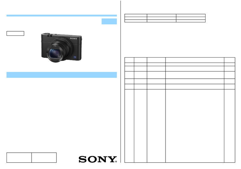
DXC-S500 (E)
Table of Contents
Manual Structure
Purpose of this manual .............................................................................................. 5
Related manuals......................................................................................................... 5
Trademarks ................................................................................................................ 5
1. Service Overview
1-1. Board Location............................................................................................1-1
1-1-1. CHU Block .................................................................................1-1
1-1-2. CCU Block .................................................................................1-1
1-2. System Connection Diagram.......................................................................1-1
1-2-1. Connecting to Video Equipment With Composite Video Input
Connectors..................................................................................1-1
1-2-2. Connecting to Video Equipment With Composite S-Video
Input Connector..........................................................................1-2
1-2-3. Connecting to a Computer .........................................................1-2
1-3. Removal and Installation of Cabinet...........................................................1-3
1-3-1. CHU Block .................................................................................1-3
1-3-2. CCU Block .................................................................................1-3
1-3-3. Gasket Plate................................................................................1-4
1-4. Removal and Installation of Board .............................................................1-5
1-4-1. CA-46 Board/PS-613 Board ......................................................1-5
1-4-2. PA-267 Board.............................................................................1-5
1-4-3. PD-106 Board.............................................................................1-6
1-4-4. SW-1082 Board..........................................................................1-6
1-4-5. LED-388 Board/PSW-77 Board ................................................1-7
1-4-6. SY-301 Board.............................................................................1-7
1-4-7. IF-847 Board ..............................................................................1-8
1-4-8. CN-2272 Board ..........................................................................1-8
1-4-9. FM-84 Board ..............................................................................1-9
1-4-10. Switching Regulator.................................................................1-10
1-5. DC Fan ......................................................................................................1-10
1-6. Removal and Installation of LCD Panel ...................................................1-11
1-7. Replacement of Lithium Battery ...............................................................1-11
1-8. Input and Output Signals of Connectors ...................................................1-12
1-9. TWAIN Driver Software Installation Procedures.....................................1-13
