Sony DDU100E User manual

©1997 by Sony Corporation Printed in Japan
DDU100E
DVD-ROM Drive Unit
User’s Guide
DDU100E
DVD-ROM Drive Unit
User’s Guide
3-860-476-11(1)

2
Owner’s Record
The model and serial numbers are located on the top side of the drive. Record these
numbers in the spaces provided below. Refer to them whenever you call upon your sales
representative regarding this product.
Model No. Serial No.
WARNING
To prevent fire or shock hazard, do not expose the unit
to rain or moisture.
To avoid electrical shock, do not open the cabinet.
Refer servicing to qualified personnel only.
CAUTION
The use of optical instruments with this product will increase eye hazard.
This unit uses CD-ROM discs with the following mark.
When you use this unit as an audio CD player, use compact
discs with the following mark.
This label is located on the top of the drive.
Dieser Aufkleber befindet sich an der Oberseite des Gehäuses.
CAUTION VISIBLE AND INVISIBLE LASER RADIATION WHEN OPEN.
DO NOT STARE INTO BEAM OR VIEW DIRECTLY WITH OPTICAL INSTRUMENTS.
VORSICHT
SICHTBARE UND UNSICHTBARE LASERSTRAHLUNGWENN ABDECKUNG GEÖFFNET.
NICHT IN DEN STRAHL BLICKEN ORDER MIT OPTISCHEN INSTRUMENTEN DIRECT ANSEHEN.
ATTENTION RAYONNEMENT LASER VISIBLE ET INVISIBLE EN CAS D’OUVERTURE.
NE PAS REGARDER DANS LE FAISCEAU NI À L’ŒIL NU NI À L’AIDE D’INSTRUMENTS D’OPTIQUE.

3
INFORMATION
You are cautioned that any changes or modifications not expressly approved in this
manual could void your warranty covering this equipment.
Note: This equipment has been tested and found to comply with the limits for a Class B
digital device, pursuant to Part 15 of the FCC Rules. These limits are designed to
provide reasonable protection against harmful interference in a residential installation.
This equipment generates, uses, and can radiate radio frequency energy and, if not
installed and used in accordance with the instructions, may cause harmful interference to
radio communications. However, there is no guarantee that interference will not occur in
a particular installation. If this equipment does cause harmful interference to radio or
television reception, which can be determined by turning the equipment off and on, the
user is encouraged to try to correct the interference by one or more of the following
measures:
– Reorient or relocate the receiving antenna.
– Increase the separation between the equipment and receiver.
– Connect the equipment into an outlet on a circuit different from that to which the
receiver is connected.
– Consult the dealer or an experienced radio/TV technician for help.
This DVD-ROM Drive Unit is classified as a
CLASS 1 LASER PRODUCT.
The CLASS 1 LASER PRODUCT label is located
on the top of the drive.
Bei diesem DVD-ROM-Laufwerk DDU100E
handelt es sich um ein Laser-Produkt der Klasse 1.
Ein entsprechender Aufkleber mit der Beschriftung
LASER KLASSE 1 PRODUKT befindet sich auf
der Oberseite des Geräts.
CLASS 1
LASER PRODUCT
LASER KLASSE 1
PRODUKT
LUOKAN 1 LASERLAITE
KLASS 1 LASER APPARAT
Diese Ausrüstung erfüllt die Europäischen EMC-Bestimmungen für die Verwendung in
folgender/folgenden Umgebung(en):
• Wohngegenden
• Gewerbegebiete
• Leichtindustriegebiete
(Diese Ausrüstung erfüllt die Bestimmungen der Norm EN55022, Klasse B.)

4
Trademarks
• MS-DOS and Windows95 are registered trademarks of Microsoft Corporation.
• Molex is a registered trademark of Molex, Inc.
• AMP is a registered trademark of AMP, Inc.

5
Contents
Introduction 6
Features.............................................................................................. 6
Software Requirement ........................................................................ 7
Example of System Setup .................................................................. 7
Location and Function of Parts and Controls 8
Front Panel ......................................................................................... 8
Rear Panel ........................................................................................ 10
Precautions 11
Installing the Drive Unit inYour Computer 12
Preparation ....................................................................................... 12
Setting the Jumpers.......................................................................... 13
Opening the Computer ..................................................................... 14
Preparing a Space for the Drive Unit ................................................ 15
Mounting the Drive Unit .................................................................... 16
Connecting the Drive Unit ................................................................. 17
Reassembling the Computer ............................................................ 20
Installing the Software Driver 21
How to Install .................................................................................... 21
Operating the Drive Unit 22
Starting the Drive Unit ...................................................................... 22
Ejecting the Disc ............................................................................... 24
How to Use the Disc Locks............................................................... 25
Specifications 27

6Introduction
Introduction
Features
The DDU100E is an internal DVD-ROM (Digital Versatile Disc
Read-Only Memory) drive for PCs running under
Windows95(OSR2). It can function as an 8 times speed CD-ROM
(Compact Disc Read-Only Memory) drive as well.
The DDU100E comes with the following features.
General
•5
1
/
4
inch half-height drive form factor.
• 512-kbyte buffer memory ATA-PI compliant (SFF-8090)
• Audio CD like drawer loading of a disc without using a caddy.
• Power loading and power eject of a disc. The disc can also be
ejected manually.
• Housed in an airtight frame casing.
Supported disc formats
• Read data from DVD-Video and DVD-ROM discs (1 or 2 layers)
• Read data from CD-R discs
• Reads data from CD-ROM, CD-ROM XA, CD-I and CD-I Ready
format discs, and from CD-EXTRA discs.
• Reads data from CD-BRIDGE format discs including PHOTO-
CD.
• Reads standard CD-Digital Audio encoded discs.
Performance
• The DDU100E supports standard speed (equivalent to 9 times
speed CD-ROM) operations when functioning as a DVD-ROM
drive, or double, quadruple and 8 times speed operations when
functioning as a CD-ROM drive. In either case, it also supports
real-time error correction.
• Fast access time ensuring reliable high-speed data access.
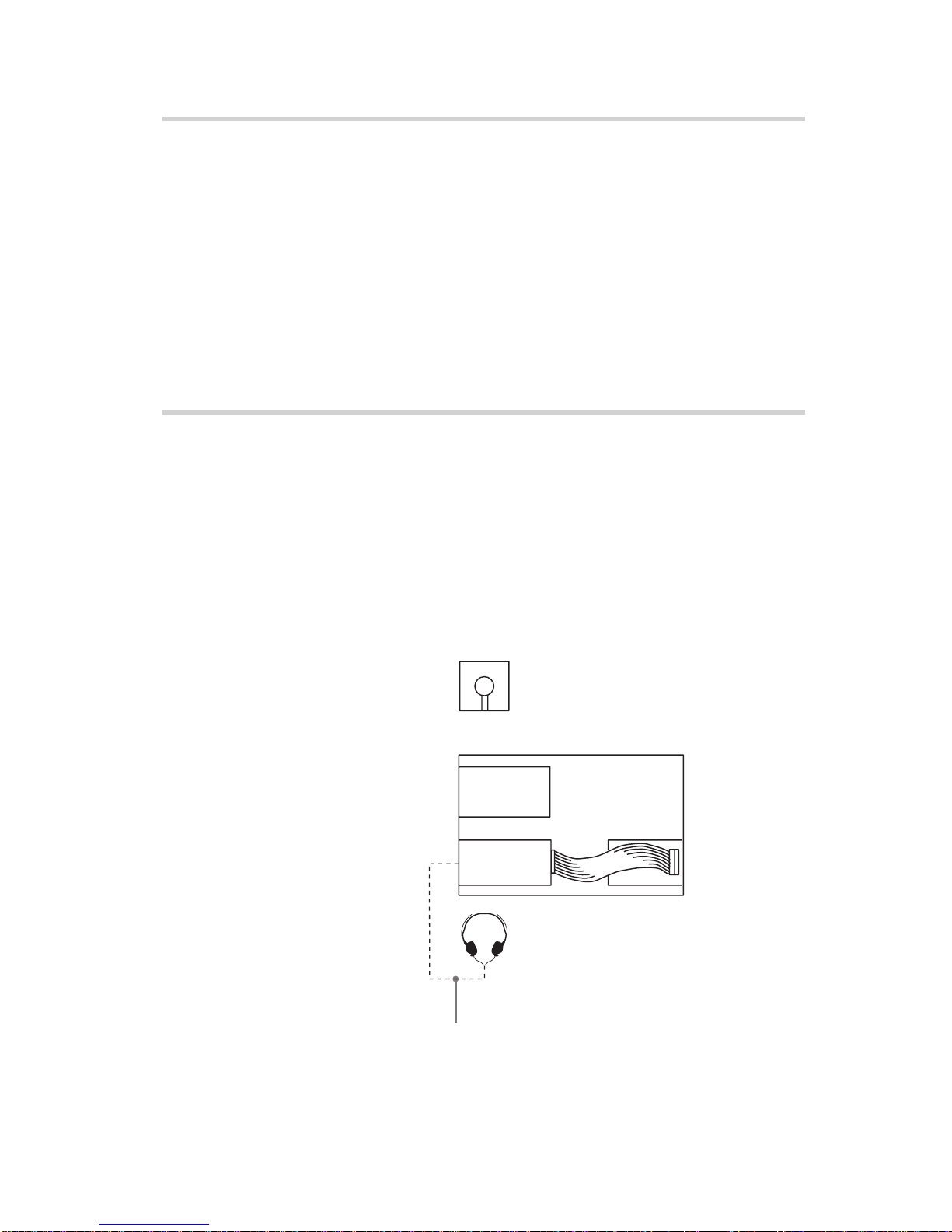
Audio
• Outputs 16-bit digital audio data over the ATA interface.
• Equipped with audio line output and headphones jack for audio
CD playback.
Note:
The DDU100E is not equipped with an ADPCM audio circuitry
required to support CD-ROM XA and CD-I compatible audio
modes. In addition, the unit does not support the CD-I graphic
decoding function; it has to be provided by the system.

7
Software Requirement
Playback of DVD-Video discs requires a PC with Windows 95
OSR2, video playback software and appropriate hardware (MPEG2
card etc.). For further details, refer to the documentation that comes
with DVD-Video playback software.
To access data on DVD-ROM or CD-ROM discs, correct device
driver must be installed on your PC.
Different software may be required depending on the type and
format of data on the discs. Therefore, be sure to refer to the
documentation that comes with the discs.
Example of System Setup
To use the DVD-ROM drive unit, the following components are
required:
• PC running under Windows95 OSR2
• Floppy disk drive
• Software (Device driver, Utilities)
The following is an example of system setup.
Introduction
Software
Host computer
Floppy disk
drive IDE port
DVD-ROM
Drive
Audio cable

8Location and Function of Parts and Controls
Location and Function of Parts and Controls
Front Panel
7
56
43
2
1
1Disc drawer
Loads a DVD-ROM or CD-ROM disc.
2Headphones jack
Accepts a stereo headphones set. Analog audio signals are
output.
3Volume control
Controls the volume level of sound output from the headphones
jack 2.
4DVD indicator
This green indicator light or goes off to indicate one of the
following unit conditions.
• Steady lit: DVD-ROM disc is loaded
• Off: CD-ROM disc is loaded
5Busy indicator
This amber indicator lights or flashes to indicate one of the
following unit conditions.
• Steady lit:TOC (table of contents) read, seek data read, or
audio playback in progress.
• Flashing: Drawer in motion.
6Emergency eject hole
Used to open the disc drawer manually when neither the eject
button 7nor a software command works. Insert a pointed
object, such as a paper clip, into this hole and push.

9
Location and Function of Parts and Controls
7Eject button
Opens and closes the disc drawer.

10
Rear Panel
12
3
456
1F. GND (Frame ground) tab
Connect with one of the host computer’s ground cables when the
frame of the drive unit is not in direct contact with the computer.
2Unused
3ANALOG AUDIO connector
Outputs analog audio signals.
4Configuration Jumpers
See page 13 for details.
5INTERFACE CONNECTOR (IDE bus)
Connect to IDE port of the host computer using a connecting
cable.
6DC INPUT (power-in) connector
Connect to the power supply of the host computer.
Pin 1
Location and Function of Parts and Controls

11
Precautions
Precautions
■Installation
• Avoid placing the drive in a location subject to:
– high humidity
– high temperature
– excessive dust
– mechanical vibration
– direct sunlight
• Do not force the power cable. It is keyed to protect the drive unit.
■Operation
• Do not move the drive when it is in use. Doing so may cause data
error and damage the optical pick-up.
• Avoid exposing the drive to sudden changes in temperature as
condensation may form on the lens inside the drive unit. Should
the surrounding temperature suddenly rise while the drive unit is
turned on, stop using the drive and leave the power on at least one
hour before operating it or turning it off. Operating the drive unit
immediately after a sudden increase in temperature may result in a
malfunction.
■Transportation
• Close the disc drawer before moving the drive unit.
• Keep the original packing materials. When you need to ship the
drive unit to another location, repacking it in its original container
will help you transport it safely.

12 Installing the Drive Unit inYour Computer
Installing the Drive Unit in Your Computer
This section explains how to install DDU100E into your PC.
Preparation
You need the following parts and tools (these are not supplied with
the drive):
• A flat-blade screwdriver
• Four screws 3 mm in diameter and 6 mm in length.
• Two mounting rails if your computer has mounting tracks.
Unplug the computer and disconnect the cables attached to the back
to give yourself more room to work. Do not turn on the power of the
computer before completing the entire installation process.

13
Installing the Drive Unit inYour Computer
Setting the Jumpers
Set the jumpers on the rear of the drive unit in accordance with the
configuration of your computer system.
The jumpers are preset at the “MASTER” position as illustrated at
the factory.
CSEL
SLAVE
MASTER
Notes for configuration jumpers:
• Designation of the Drive Number is generally set by inserting a
jumper pin on either the MASTER or the SLAVE pin.
• When the DDU100E is daisy-chained with a Hard Disk Drive on
an IDE Card (ATA compliant) set the Hard Disk Drive as
MASTER and the DDU100E as SLAVE.
• If the DDU100E is the only device connected to the IDE Card, set
the DDU100E as MASTER.
It should be noted that some personal computers may use CSEL in
lieu of the foresaid MASTER/SLAVE selection. In this case, remove
the existing jumpers from MASTER and SLAVE, and set a jumper
on CSEL. When the CSEL signal of the interface connector is set
low, the drive is designated as Drive 0. When the CSEL is set high,
the drive is designated as Drive 1.
Consult your PC manufacturer or dealer for further details.

14 Installing the Drive Unit inYour Computer
Computer Remove the plastic panel.
Rear plastic panel
Cover mounting screw
Remove the screws.
Remove the computer cover.
Opening the Computer
1If your computer has its rear side covered by a plastic panel
attached with plastic hook pad, pull it off.
2Remove the cover mounting screws.
3Remove the cover of the computer.

15
Installing the Drive Unit inYour Computer
Floppy disk drive
Lower drive bay
blanking plate
Remove the screws
and brackets.
Floppy disk drive
Floppy disk drive
Blanking plate
Preparing a Space for the Drive Unit
1Remove the screws and brackets securing the floppy disk drive
and the lower drive bay blanking plate.
2Disconnect the floppy disk drive.
3Remove the floppy disk drive and the blanking plate.

16 Installing the Drive Unit inYour Computer
Mounting the Drive Unit
If mounting rails are necessary, attach them to the drive in unit the
same way as your floppy disk drive and slide the drive unit into the
lower drive bay. If mounting rails are not required in your system,
fasten the drive unit in place with mounting screws.
Slide the drive unit into the lower bay.

17
Connecting the Drive Unit
Connect the drive unit to the computer with the following
connectors:
• DC INPUT connector
• F. GND tab (unless the frame of the drive unit is in direct contact
with the computer’s chassis).
• AUDIO OUT connector (if you plan to connect audio equipment)
• INTERFACE CONNECTOR.
■DC INPUT connector
The pin assignment is as follows.
After matching the beveled edges, insert the plug of the power
supply cable to the DC INPUT connector and push it firmly in place.
Caution: Improper connection may damage the drive unit and void
the warranty.
Installing the Drive Unit inYour Computer
F. GND tab
AUDIO
OUT
connector
INTERFACE CONNECTOR
DC INPUT
connector
GND GND
+5 V DC
DC INPUT connector
Power supply cable
(4-pin connection cable)
+12 V DC

18
■F. GND tab
Connect the F. GND tab to one of the host computer’s ground cables
unless the frame of the drive unit is in direct contact with the
computer’s chassis (a situation not likely under normal
circumstances).
The frame ground cable recommended is the one using an AMP 1-
480435-0 housing and 170203-2 or 60711-1 contact.
■AUDIO OUT connector
The pin assignment is as follows:
pin Audio Signal
1 R singal
2 R ground
3 L ground
4 Lsignal
Installing the Drive Unit inYour Computer
F. GND tab
Frame ground cable

19
■INTERFACE CONNECTOR
1Firmly insert one end of the interface cable into the INTERFACE
CONNECTOR.
2Connect the other end of the cable to the IDE port.
Installing the Drive Unit inYour Computer
Pin 1
INTERFACE
CONNECTOR
Interface cable

20
Reassembling the Computer
1Reinstall the floppy disk drive in the top drive bay.
2Reconnect the interface cables to the floppy disk drive.
3Fasten the screws and front brackets as they were before.
4Tuck the cables behind the drive so that they do not protrude
above the power supply module.
5After checking the following points, slide the computer’s cover
on and fasten the cover mounting screws at the back of the
computer.
• Are the connections between the drive unit and computer
correct?
• Are the jumpers set to the appropriate positions?
6Remount the rear plastic panel and refer back to the proper
installation section if you answered “no” to either of the
questions above.
Installing the Drive Unit inYour Computer
Reinstall the floppy disk drive.
Tuck the cables.
Power supply
Table of contents
Other Sony DVD Drive manuals

Sony
Sony VRD-MC1 Nero 6 User manual

Sony
Sony ODS-D280U User manual

Sony
Sony ODS-D380U User manual

Sony
Sony DRU-500AX User manual

Sony
Sony PCGA-DDRW2 User manual

Sony
Sony DRX-800UL User manual

Sony
Sony DRX-700UL User manual

Sony
Sony DRU-700A User manual

Sony
Sony DRU110A User manual

Sony
Sony DRXS50U - DRX S50U User manual

Sony
Sony DVDirect VRD-MC3 User manual

Sony
Sony DRX-820UL User manual

Sony
Sony DRU-530A User manual

Sony
Sony MPD-AP20U User manual

Sony
Sony DRX-S77U User manual

Sony
Sony AW-G170A-B2 Specification sheet

Sony
Sony VAIO PCGA-CDRW52 User manual

Sony
Sony DDU220E User manual

Sony
Sony DDU1681S Datasheet

Sony
Sony DDU1621 Series User manual