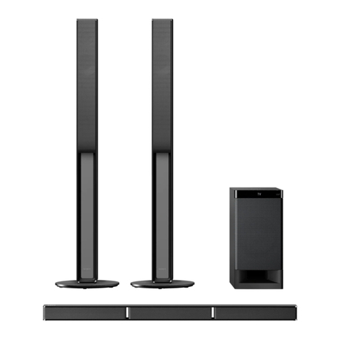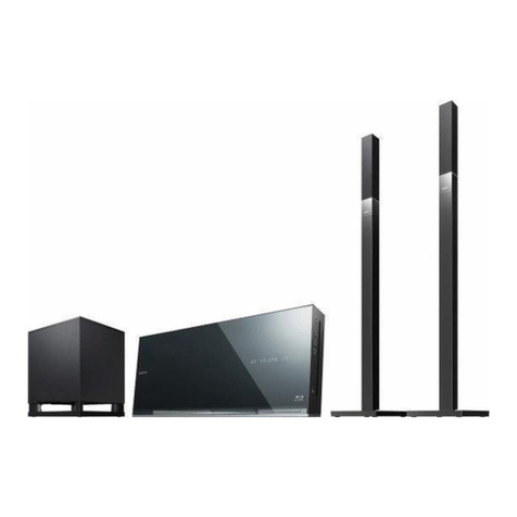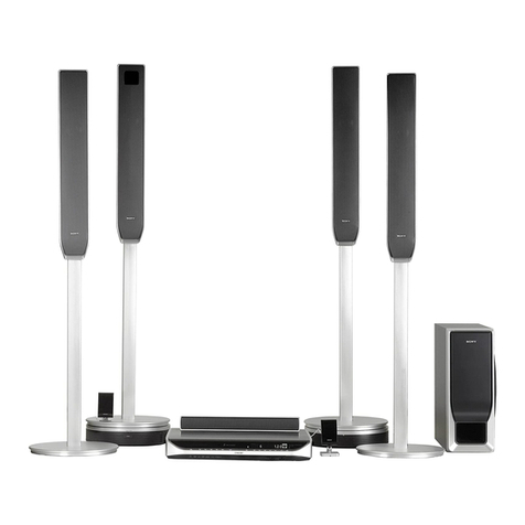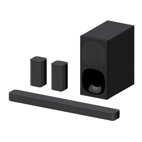
DAV-IS50
Quick Start Guide
You can enjoy the system by performing the
preparation in this Quick Start Guide.
For details, refer to the operating instructions.
Guía de inicio
rápido
Podrá utilizar el sistema tras realizar los
preparativos que se indican en esta Guía de inicio
rápido.
Para obtener información detallada, consulte el
manual de instrucciones.
,
English
AUnpacking
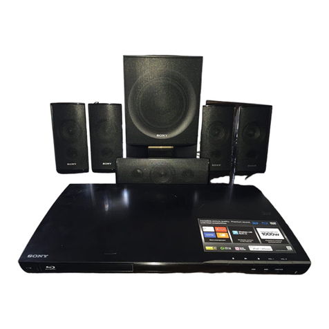
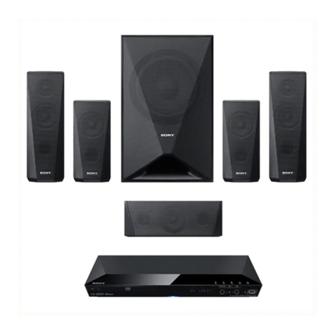
AControl unit
BFront left speaker
(white connector, 4.5 m cord)
CCenter speaker
(green connector, 3.0 m cord)
DFront right speaker
(red connector, 4.5 m cord)
ESurround left speaker
(blue connector, 12.0 m cord)
FSurround right speaker
(gray connector, 12.0 m cord)
GSubwoofer
HAM loop antenna (aerial)
IFM wire antenna (aerial)
JVideo Cord (yellow)
KRemote Commander (remote)
LR6 (size AA) batteries (2)
MCalibration microphone
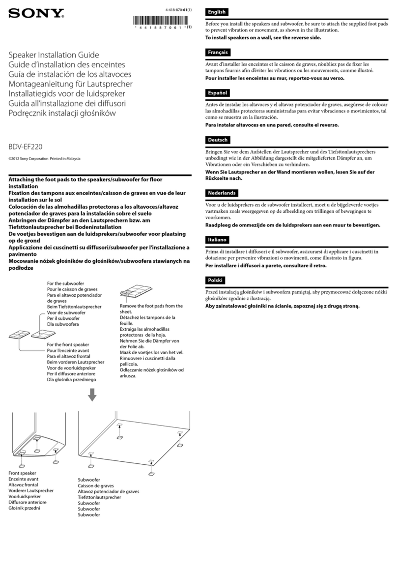
5Do not place objects on the top of
the subwoofer where the speaker
unit is installed.
6Do not place the subwoofer
under a desk or in a cabinet, etc.
7Do not place the subwoofer back
of the obstruction, such as TV,
etc. Middle range sound will fall.
CConnecting the
speakers
• Before connecting the speakers,
place the subwoofer on a stable
work surface that is larger than the
subwoofer.
• Be sure to place a soft cloth on the
work surface to avoid damaging the
surface of the subwoofer.
• Connect the connectors of the
speaker cords to the corresponding
SPEAKER jacks. The connectors of
the speaker cords have the same
color as the jacks to be connected.
BPositioning the
speakers
For the best possible surround sound,
all the speakers other than the
subwoofer should be placed at the
same distance from the listening
position (1). It is recommended that
the subwoofer should be placed (2).
Note
Image distortion on the TV screen
may occur depending on the location
of the subwoofer. In this case, place
the subwoofer away from the TV.
3If the subwoofer is to be placed
ahead of the front speaker, the
distance should be less than
0.5 m1).
4You may not get the bass sound
efficiently when the subwoofer is
placed outside2). You need to
adjust the setting of the distance
from the listening position.
Français
ADéballage
AAppareil de commande
BEnceinte avant gauche
(connecteur blanc, cordon de
4,5 m)
CEnceinte centrale
(connecteur vert, cordon de
3,0 m)
DEnceinte avant droite
(connecteur rouge, cordon de
4,5 m)
EEnceinte surround gauche
(connecteur bleu, cordon de
12,0 m)
FEnceinte surround droite
(connecteur gris, cordon de
12,0 m)
GCaisson de grave
HAM Antenne cadre (aérienne)
IFM Antenne fil (aérienne)
JCordon vidéo (jaune)
KTélécommande (infrarouge)
LR6 Piles (format AA) (2)
MMicrophone de calibrage
BPositionnement
des enceintes
Pour optimiser le son surround, toutes
les enceintes, hormis le caisson de
grave, doivent être à égale distance de
la position d’écoute (1). Il est
recommandé de placer le caisson de
grave à la position (2).
Remarque
La position du caisson de grave peut
déformer l’image de l’écran du
téléviseur. Si c’est le cas, éloignez le
caisson de grave du téléviseur.
3Si le caisson de grave doit être
placé devant l’enceinte avant, la
distance entre eux doit être
inférieure à 0,5 m1).
4Il se peut que les graves ne soient
pas correctement reproduites si le
caisson de grave est placé en
dehors de la zone2). Vous devez
régler la distance par rapport à la
position d’écoute.
5Ne placez aucun objet sur le
dessus du caisson de grave, à
l’emplacement du haut-parleur.
6Ne placez pas le caisson de grave
sous un bureau, dans une
armoire, etc.
7N’installez pas le caisson de
grave dos à un obstacle, tel qu’un
téléviseur, etc. Les médiums
reproduits risquent d’être altérés.
CRaccordement
des enceintes
• Avant de raccorder les enceintes,
posez le caisson de grave sur une
table stable plus grande que le
caisson de grave.
• Recouvrez la table d’un tissu doux
pour éviter d’endommager la
surface du caisson de grave.
• Branchez les connecteurs des
cordons d’enceintes sur les prises
SPEAKER correspondantes. Les
connecteurs des cordons
d’enceintes sont de même couleur
que les prises sur lesquelles ils
doivent être branchés.
• Marquez vos enceintes pour être
sûre de la position de chaque
enceinte.
DRaccordement
de la chaîne et
du téléviseur
Cet exemple illustre le raccordement
de base de la chaîne au téléviseur.
Le cordon audio (rouge/blanc) n’est
pas fourni.
3) Veillez à raccorder le cordon
d’alimentation (cordon secteur) en
dernier.
• Mark your speakers so that you can
be sure of each speaker position.
DConnecting the
system and TV
This hookup is the basic connection
of the system and TV.
An audi cord (red/white) is not
supplied.
3) Be sure to connect the AC power cord
(mains lead) last.
A
A
B
,
C
,
D,
E,
F,
G
HAM
IFM
J
K
LR6AA(2)
M
C
• ,
•
•
SPEAKER
•
D
!"#
3)
AC
B $%&#
,
1
2
$'()
,
3
,
(1
4
(2
5
6
…,
7
, …,
© 2008 Sony Corporation Printed in Malaysia
A
A BCDEF G
HI J
KL M
B
D
G
A
C
F
E
B
21 1 21
2
121
2
CG
D
F
B
E
34
56
7
1) 2) 2)
TV, etc.
Téléviseur, etc.
…,
CD
SYSTEM CONTROL
ONLYFOR HCD-IS50
SPEAKER
ONLY FOR SS-IS15
CENTERSUR LSUR RFRONT LFRONT R
SYSTEM CONTROL
ONLY FOR HCD-IS50
SPEAKER
ONLY FOR SS-IS15
CENTERSUR LSUR RFRONT LFRONT R
DMPORT
R
AUDIO
OUT
L
VIDEO
IN
Bottom of
the
subwoofer
Dessous du
caisson de
grave
Soft cloth
Chiffon doux
DBC
G
FE
I
H
J
A
G
Audio cord (not supplied)
Cordon audio (non fourni)
TV (AUDIO IN)
VIDEO OUT (VIDEO)
TV
Téléviseur
AC power cord (mains lead)3)
Cordon d’alimentation CA (secteur)3)
AC
3)
To wall outlet
(mains)
Á une prise
murale (secteur)
3-299-550-71(1)
(1)

