KDL-32/40EX720,721,723,724(AEP/UK) 10
SELF DIAGNOSIS FUNCTION
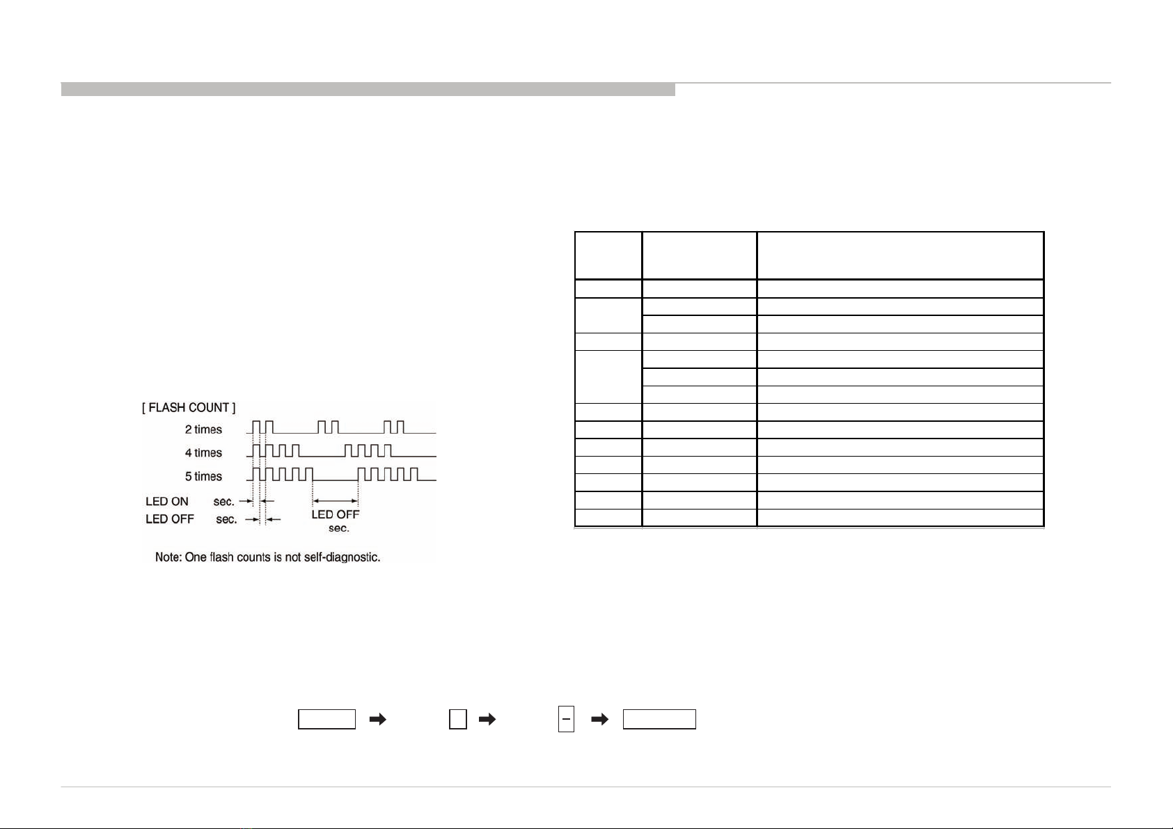
DIAGNOSTIC TEST INDICATORS
When an error occurs, the STANDBY LED will flash a set number of times to
indicate the possible cause of the problem.
If there is more than one error, the LED will identify the first of the problem areas.
Result for all of the following diagnostic items are displayed on screen.
If the screen displays a “0”, no error has occurred .
The units in this manual contain a self-diagnostic function. If an error occurs, the STANDBY LED will automatically begin to flash.
The number of times the LED flashes translates to a probable source of the problem.
A definition of the STANDBY LED flash indicators is listed in the instruction manual for the user’s knowledge and reference.
If an error symptom cannot be reproduced, the remote commander can be used to review the failure occurrence data stored in memory to reveal past problems and how often these
problems occur.
0.5
0.5 3
DISPLAY OF STANDBY LED FLASH COUNT
SELF-DIAGNOSTIC SCREEN DISPLAY
For errors with symptoms such as “power sometimes shuts off” or “screen sometimes goes out” that cannot be confirmed, it is possible to bring up past occurrences of failure for
confirmation on the screen:
[To Bring Up Screen Test]
In standby mode, press buttons on the remote commander sequentially in rapid succession as shown below:
5
*: Note that this differs from entering the service mode (volume +)
*
DISPLAY TV POWERChannel Volume
STBYLED
Flash time
Service menu Item
name
(Screen Display) Diagnostic Item Description
2 MAIN_POWE Main Power Over Voltage Protection
DC_ALERT DC_ALERT
AUD_PROT Audio Abnormal Detection
4 BALANCER Panel Balancer Error
TCON_ERR Notused
HFR_ERR HFR Error
P_ID_ERR Panel ID NVMError
6 BACKLITE Back Light Error (Panel Inverter)
7TMP_ERR Thermal Error
8 - Software Error
9 - Notused
10 EMIT_ERR Emitter Error
11 - Reserved for BTV
12 - Notused
3
5
Note: codes 101~104 can be seen on OSD (See Page 11) which are not error
codes for service.