6$)(7<127(6
6(&7,21
3)Check all control knobs, shields, covers, groundstraps and mounting
hardwarehave beenreplaced.Be absolutely certain you have replacedall
the insulators.
4) Look for unauthorizedreplacementparts, particularly transistors that were
installed during apreviousrepair Point them out to the customerand
&DXWLRQ+DQGOLQJRI/&'3DQHO
When repairingthe LCD Panel, make sure you are grounded with a wrist band.
When repairingthe LCD Panel on the wall, the panel must be securedusing the 4
mountingholes on the rear cover.
1) Do not press the panelor frame edge to avoid the risk of electric shock.
recommendtheir replacement.
5)Lookforparts which,though functioning showobvious signsof deterioration.
Point them out to the customerand recommend their replacement.
6) Check the line cords for cracks and abrasion. Recommend the replacement
of any such line cord to the customer.
2) Do not scratch or press on the panel with any sharp objects.
3) Do not leave the module in high temperatureor in areas of high humidity for
an extended period of time.
4) Do not expose the LCD panelto direct sunlight.
5) Avoid contact with water. It may cause short circuit within the module.
)Disconnect the AC powerwhen replacing the backlight (CCFL)or
7) Check the antenna terminals, metal trim, "metallized“ knobs, screws and all
other exposedmetal parts for AC leakage.Check leakage test as described
next.
8)Forsafety reasons, repairing the PowerBoard and/orinverterboard is prohibited.
inverter circuit. (High voltageoccurs at the inverter circuit at 650Vrms)
7) Always clean the LCD panelwith a soft cloth material.
8) Use care when handlingthe wires or connectors of the inverter circuit.
Damagingthe wires may cause a short circuit.
9) Protect the panelfrom ESD to avoid damagingthe electronic circuit
The AC leakage from any exposedmetal part to earth groundand from all exposed
metal parts to any exposedmetal part havinga return to chassis must not exceed
0.5mA (500 microamperes).
Leakage currentcan be measured by any one of the three methods:-
1. A commercial leakagetester such as the SIMPSON 229 or RCA WT-540A.
(C-MOS).
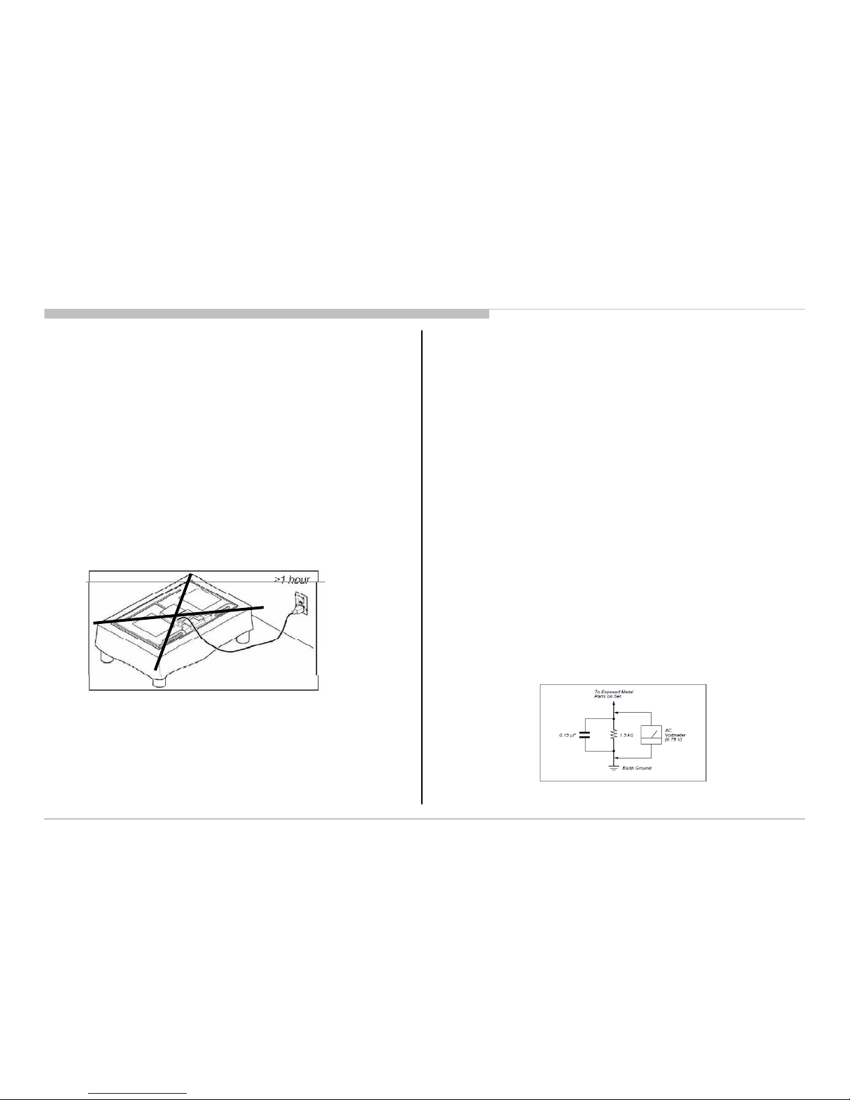
10) During the repair, DO NOT leave the Power On or Burn-in period for more than
1 hour while the TV is face down on a cloth.
Follow the manufacturers instructionsto use those instructions.
2. A battery-operated AC milliampmeter. The DATA PRECISION 245 digital
multimeter is suitable for this job.
3. Measuringthe voltage drop across a resistor by means of a VOM or battery
operated AC voltmeter. The 'limit' indication is 0.75V so analogmeters must
have an accurate low voltage scale The SIMPSON
SH-63TRD are examples of passive VOMs that are suitable.Nearly all
battery operated digital multimeters that have a 2 VAC rangeare suitable.
(see Figure 2.)
Figure 1. TVis faced down on a cloth during repair.
6DIHW\&KHFN2XW
After correctingthe originalservice problem, perform the following safety checks
beforereleasingthe set to the customer:-
1) Check the area of your repair for unsolderedor poorly soldered connections.
Check the entire board surface for solder splashesand bridges.
5
Figure 2. AC voltmeter to check AC leakage
2)Check theinterboardwiringto ensure thatnowiresarepinched orcontact
high-wattage resistors.
./9(;(;$(;%(;(;$(;%
50*$


 User manual")

 User manual")


 User manual")