manuals.online logo
Brands
  1. Home
  2. •
  3. Brands
  4. •
  5. Sony
  6. •
  7. LCD TV
  8. •
  9. Sony KDL-32EX500 - Bravia Ex Series Lcd... User manual

Sony KDL-32EX500 - Bravia Ex Series Lcd... User manual

KDL-32/37/40/46/55EX500
Series(AEP/UK)
AZ1-LCHASSIS
Segment: 3a-1
SERVICE MANUAL
HISTORY INFORMATION FOR THE FOLLOWING MANUAL:
ORIGINAL MANUAL ISSUE DATE: 1/2010
Version Date Subject
1.0 1/2010 No revisions or updates are applicable at this time.
2.0 2/2010 Amend 32”(P.42) & 37”(P.45) EX504 ‘BAL’ board part number.
3.0 5/2010 Add updated Panel Caution Note (P.6).
Add Inverterand Tcon Board Part Numbers (P.42,45,48,51,54).
Add illustration showing location of neck to base screws (P.43,46,49,52,55).
Add ‘Support, Panel’ Part Numbers (P.41,44,47,50,53).
4.0 6/2010 Add ‘Hotel Assy’ to Exploded Views (P.41,44,47,50,53).
Add ‘Hotel Addendum’for B2B Models (P.59).LCD Digital Color TV
9-888-265-04
KDL-32/37/40/46/55EX500
Series(AEP/UK)
SERVICE MANUAL
LCD Digital Color TV
AZ1-LCHASSIS
Segment: 3a-1
9-888-265-04
KDL-32/37/40/46/55EX500 Series(AEP/UK) 3
MODEL LIST
MODEL COLOR COMMANDER DEST.MODEL COLOR COMMANDER DEST.
KDL-32EX500 Black RM-ED035 AEP
KDL-32EX501 Black RM-ED035 AEP
KDL-32EX503 Black RM-ED035 UK
KDL-32EX504 Black RM-ED035 AEP
KDL-32EX505 Black RM-ED035 AEP
KDL-32EX508 Black RM-ED033 AEP
KDL-37EX500 Black RM-ED035 AEP
KDL-37EX503 Black RM-ED035 UK
KDL-37EX504 Black RM-ED035 AEP
KDL-37EX505 Black RM-ED035 AEP
KDL-40EX500 Black RM-ED035 AEP
KDL-40EX501 Black RM-ED035 AEP
KDL-40EX503 Black RM-ED035 UK
KDL-40EX505 Black RM-ED035 AEP
KDL-40EX508 Black RM-ED033 AEP
KDL-46EX500 Black RM-ED035 AEP
KDL-46EX501 Black RM-ED035 AEP
KDL-46EX503 Black RM-ED035 UK
KDL-46EX505 Black RM-ED035 AEP
KDL-55EX500 Black RM-ED035 AEP
KDL-55EX503 Black RM-ED035 UK
KDL-55EX505 Black RM-ED035 AEP
KDL-32/37/40/46/55EX500 Series(AEP/UK) 4
WARNINGS AND CAUTIONS -ENGLISH
CAUTION
These servicing instructions are for use by qualified service personnel only.
To reduce the risk of electric shock, do not performany servicing other than thatcontained in the operating instructions unless you are qualified to
do so.
WARNING!!
An isolation transformer should be used during any service toavoid possible shock hazard, because of live chassis.
The chassis of this receiver is directlyconnected to the ac power line.
CARRYING THE TV
Be sure to follow these guidelines to protect your property and avoid causing serious injury.
•Carry the TV with an adequatenumber of people; larger size TVs require two or more people.
•Correct hand placement while carrying the TV isvery important for safetyand to avoid damages.
SAFETY-RELATED COMPONENT WARNING!!
Components identified by shading and ! mark on the schematic diagrams, exploded views, and in the parts list are critical for safe operation.
Replace these components with Sony parts whose part numbers appear as shown in this manual or in supplements published by Sony. Circuit
adjustments that are critical for safe operation are identified inthis manual. Follow these procedures whenever critical components are replaced or
improper operation is suspected.
KDL-32/37/40/46/55EX500 Series(AEP/UK) 5
WARNINGS AND CAUTIONS -FRENCH
ATTENTION!!
Ces instructions de service sont à l’usage du personnel de service qualifi é seulement.
Pour prévenir le risque de choc électrique, ne pas faire l’entretien autre que celui contenu dans le Mode d’emploi à moins que vous soyez qualifi é
faire ainsi.
WARNING!!
Afi n d’eviter tout risque d’electrocution provenant d’un chássis sous tension, un transformateur d’isolement doit etre utilisé lors de tout
dépannage. Le chássis de ce récepteur est directement raccordé àl’alimentation du secteur.
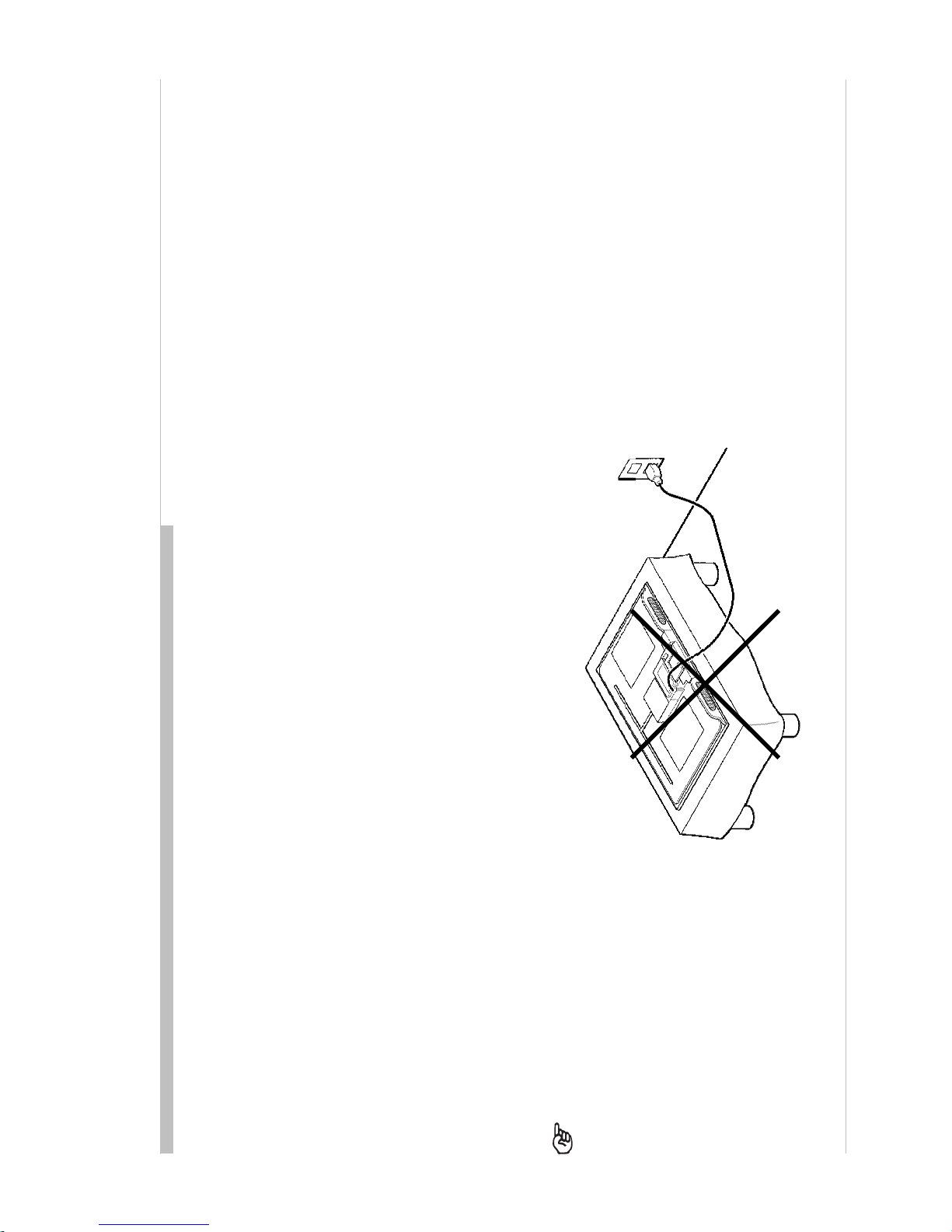
POUR TRANSPORTER LE TÉLÉVISEUR
Tenez compte de ce qui suit pendant l’installation du téléviseur :
•Débranchez tous les câbles avant de transporter le téléviseur.
•Transportez le téléviseur avec le nombre de personnes approprié ; un téléviseur de grande taille doit être transporté par au moins deux personnes.
•Lors du transport du téléviseur, l’emplacement des mains est très important pour votre sécurité, ainsi que pour éviter de causer des dommages.
ALERTE!!
Afi n d’eviter tout risque d’electrocution provenant d’un chassis sous tension, un transformateur d’isolement doit etre utilise lors de tout
depannage. Le chassis de ce recepteur est directement raccorde a l’alimentation du secteur.
ATTENTION AUX COMPOSANTS RELATIFS A LA SECURITE!!
Les composants identifi es par une trame et par une marque ! sur les schemas de principe, les vues explosees et les listes de pieces sont d’une
importance critique pour la securite du fonctionnement. Ne les remplacer que par des composants Sony dont le numero de piece est indique dans
le present manuel ou dans des supplements publies par Sony. Les reglages de circuit dont l’importance est critique pour la securite du
fonctionnement sont identifi es dans le present manuel. Suivre ces procedures lors de chaque remplacement de composantscritiques, ou lorsqu’un
mauvais fonctionnement suspecte.
KDL-32/37/40/46/55EX500 Series(AEP/UK) 6
WARNINGS AND CAUTIONS
USE CAUTION WHEN HANDLING THE LCD PANEL
When repairing the LCD panel, be sure you are grounded by using a wrist band.
When repairing the LCD panel on the wall, the LCD panel must be secured using the 4 mounting holes on the rear cover.
1) Do not press on the panel or frameedge to avoid the risk of electric shock.
2) Do not scratch or press on the panel with any sharp objects.
3) Do not leave the module in high temperatures or in areas of high humidity for an extended period of time.
4) Do not expose the LCD panel to direct sunlight.
5) Avoid contact with water. It may cause a short circuit within the module.
6) Disconnect the AC powerwhen replacing the backlight (CCFL) or invertercircuit. (High voltage occurs at the inverter circuit at 650Vrms.)
7) Always clean the LCD panel with a soft cloth material.
8) Use care when handling the wires or connectors of the invertercircuit. Damaging the wires may cause a short.
9) Protect the panel from ESD to avoid damaging the electronic circuit (C-MOS).
10) It is recommended not to exceed 1 hour of Power-On nor Burn-in period with LCD panel face down condition, in repair activity.
KDL-32/37/40/46/55EX500 Series(AEP/UK) 7
SAFETY CHECK-OUT
After correcting the original service problem, performthe following safety checks before
releasing the set to the customer:
1. Check the area of your repair for unsoldered or poorly soldered connections. Check the entire
board surface for solder splashes and bridges.
2. Check the interboard wiring to ensure that no wires are “pinched” or touching high-wattage
resistors.
3. Check thatall control knobs, shields, covers, ground straps, and mounting hardware have been
replaced. Be absolutely certain that you have replaced all the insulators.
4. Look for unauthorizedreplacement parts, particularly transistors, that were installed during a
previous repair. Point themout to the customer and recommend their replacement.
5. Look for parts which, though functioning, show obvious signs of deterioration. Point themout
to the customerand recommend their replacement.
6. Check the line cords for cracks and abrasion. Recommend the replacement of any such line
cord to the customer.
7. Check the antenna terminals, metal trim, “metallized” knobs, screws, and all other exposed
metal parts for AC leakage. Check leakage as described below.
8. For safety reasons, repairing the Power board and/or Inverter board is prohibited.
KDL-32/37/40/46/55EX500 Series(AEP/UK) 8
SAFETY CHECK-OUT
Leakage Test
The AC leakage from any exposed metal part to earth ground and from all exposed metal parts to
any exposed metal part having a returnto chassis, must not exceed 0.5 mA (500 microamperes).
Leakage current can be measured by any one of three methods.
1. A commercial leakage tester, such as the Simpson 229 or RCA WT-540A. Follow the
manufacturers’ instructions to use these instructions.
2. A battery-operated AC milliampmeter. The Data Precision 245 digital multimeter is suitable
for this job.
3. Measuring the voltage drop across a resistor by means of a VOM or battery-operated AC
voltmeter. The “limit”indication is 0.75 V, so analog meters must have an accuratelow
voltage scale.
The Simpson’s 250 and Sanwa SH-63TRD are examples of passive VOMs that are suitable.
Nearly all battery-operated digital multimeters that have a 2 VAC range are suitable (see
Figure A).
Howto Find a Good Earth Ground
A cold-waterpipe is a guaranteed earth ground; the cover-plate retaining screw on most AC outlet
boxes is also at earth ground.
If the retaining screw is to be used as your earth ground, verify that itis at ground by measuring the
resistance between it and a cold-water pipe with an ohmmeter. The reading should be zero ohms.
If a cold-water pipe is not accessible, connect a 60- to 100-watt trouble- light (not a neon lamp)
between the hot side of the receptacle and the retaining screw. Try both slots, if necessary, to
locate the hot side on the line; the lamp should light at normalbrilliance ifthe screw is at ground
potential (see Figure B).
KDL-32/37/40/46/55EX500 Series(AEP/UK) 9
SELF DIAGNOSIS FUNCTION
DIAGNOSTIC TEST INDICATORS
When an error occurs, the STANDBY LED will flash a set number
of times to indicate the possible cause of the problem.
If there is more than one error, the LED will identify the first ofthe
problemareas.
Result for all of the following diagnostic items are displayed on
screen.
If the screen displays a “0”, no error has occurred .
The units in this manual contain a self-diagnostic function. If an error occurs, the STANDBY LED will automatically begin to flash.
The number of times the LED flashes translates to a probablesource of the problem.
A definition of the STANDBY LED flash indicators is listed in the instruction manualfor the user’s knowledge and reference.
If an error symptom cannot be reproduced, the remote commander can be used to review the failure occurrence data stored in memoryto reveal past
problems and how often these problems occur.
STBYLED
Flash time Servicemenu Itemname
(ScreenDisplay)Diagnostic ItemDescription
2MAIN_POWEMain Power Over Voltage Protection
DC_ALERTDC_ALERT
DTT_WDTDTT Error
AUD_PROTAudioAbnormalDetection
4BALANCER_PanelBalancerError
TCON_ERR T-CONError
HFR_ERR HFRError
P_ID_ERR Panel IDNVMError
6BACKLITE_Back LightError (Panel Inverter)
TEMP_ERR ThermalError
FAN_ERRFANError (NotDetected. DisplayOnly)
8-Notused
9-Notused
10 -Notused
11 -Notused
12 -Notused
-RGB_SEN RGB Sensor ACK Error
3
5
7
KDL-32/37/40/46/55EX500 Series(AEP/UK) 10
SELF DIAGNOSIS FUNCTION
0.5
0.5 3
DISPLAY OF STANDBY LED FLASH COUNT
SELF-DIAGNOSTIC SCREEN DISPLAY
For errors with symptoms such as “power sometimes shuts off” or “screen sometimes goes out” that cannot be confirmed, itis possible to bring up
past occurrences of failure for confirmation on the screen:
[To Bring Up Screen Test]
In standby mode, press buttons on the remote commander sequentially in rapid succession as shown below:
KDL-32/37/40/46/55EX500 Series(AEP/UK) 11
SELF DIAGNOSIS FUNCTION
0501210811 0412311234 0311111825 00
0000000000 0000000000 0000000000 00
0000000000 0000000000 0000000000 00
0000000000 0000000000 0000000000 00
0000000000 0000000000 0000000000 00
0000000000 0000000000 0000000000 00
SELF CHECK(1)
002 MAINP
003 DC_ALERT1
004 DC_ALERT2
006 BL
007 TEMP
009 FAN
12345-00333-06789
<1> NEXT PAGE->
Errorcount (00-99)
Errorhistory(Last failuretimebeforehand)
Error history (Failuretime beforelast)
Error history (The last failure time)
Item name
STBYLED flash time
Total operation timeby hour(MAX:65535)
Boot count (MAX:65535)
Panel operation timeby hour (MAX:65535)
[SELF DIAGNOSTIC SCREEN DISPLAY]
KDL-32/37/40/46/55EX500 Series(AEP/UK) 12
SELF DIAGNOSIS FUNCTION
Since the diagnostic results displayed on the screen are not automatically cleared, always check the self-diagnostic screen.
After you have completed the repairs, clear the result display to “0”.
Clearing the Self Check Diagnostic List
1. Error history and Error count : Press the Channel 8 => Channel 0 .
2. Panel operation time : Press the Channel 7 => Channel 0 .
Exiting the Self-diagnostic screen
To exit the Self Diagnostic screen, turn off the power to the TV by pressing the POWER button on the remote or the POWER button on
the TV.
KDL-32/37/40/46/55EX500 Series(AEP/UK) 13
SEC 1. DISASSEMBLY
KDL-32EX500 Series
KDL-32EX500 Series
1-1. MOVIE LIST
KDL-37EX500 Series
KDL-37EX500 Series
KDL-40EX500 Series
KDL-40EX500 Series
KDL-46EX500 Series
KDL-46EX500 Series
KDL-55EX500 Series
KDL-55EX500 Series
KDL-32/37/40/46/55EX500 Series(AEP/UK) 14
CHASSIS SERVICE
000 CXD2813R
000 H_DET_NOSIG_CNT 1
SEC 2. ADJUSTMENT
HOW TO ENTERING SERVICE MODE
1) Turn on the main power switch to place this set in standby mode.
2) Press the buttons on the remotecommander as follows, and entering service mode.
3) Service mode display.
Note: First of all, when you enter Service Mode, you can see “Digital”service mode.
Whenever you press “OPTIONS” or “JUMP” on remote, each service mode is changed.
“Digital”-> “Chassis” -> “Sub”
DIGITAL SERVICE
001 OP
000 VERS ---
<MAIN><SUB>
DM1.301J00AA SM1.010W00AA
M2.105C SB1.000W00AA
DD1.016J00AA SD1.010W00AA
(DM1.301J00AA) RF01.05
WP00.521J00AA ID1C117081
ID1C117081 LTY320AB01
PID04020000
WF:2.0.0.99 <BEM>
WF:0B BM1.012W00LU
Camera FW BB1.000W00LU
Camera FW BD1.011J46LUX
---.---------
Item number
Category number
Item name
Category name
Data
Press “OPTIONS”
or “JUMP” button
KDL-32/37/40/46/55EX500 Series(AEP/UK) 15
ADJUSTMENT
4) How to use the remote commander.
5) After entering service mode, then turn offthe power switch.
<Test>+<TV>/<Display><5><Vol Up><Power>Service mode on
<Other> / <Poweroff + on>Service mode off
<Jump> / <Option>
<Mute> + <0>
<10 or0>
<9> + <0>
<8> + <Mute>+ <0>
<3>/<6>
<2>/<5>
<1>/<4>
The flowof control
Change module
Write data
Execute
Read data
Test reset
Data up / down
Categoryup / down
Item up / down
Function
KDL-32/37/40/46/55EX500 Series(AEP/UK) 16
ADJUSTMENT
WHITE BALANCE ADJUSTMENT
Change Dataof “Digital” service mode. (“006 WB” category)
a. Press “0” or “10” on remoteto enter WB adjustment mode.
b. Press number key “1”~”6” directly. “*” stamp move.
c. Press “12 / enter / select” to decide and advance next step.
When returning on the previous page, press “return”.
d. Change data by number key “0”~”9”directly. (0-255)
e. Press “12 / enter / select” to save data.
It shows red “WRITE”. It indicatewriting is processing.
f. Writing process is done at this point.
DIGITAL SERVICE
006 WB
000 WHITE_BALANCE ___
DIGITAL SERVICE
WB
*1 R_DRV 128
2 G_DRV 128
3 B_DRV 128
4 R_BKG 128
5 G_BKG 128
6 B_BKG 128
Please input WB items
(0-255)
---
Gain
0: x 0.5, 128: x 1, 255: x1.5
Offset
128: offset 0
KDL-32/37/40/46/55EX500 Series(AEP/UK) 17
SAVE CHANGING DATA
1) Change Data of “Chassis” or “Sub”service mode
2) Write data for “Chassis” or “Sub” service mode
a. Press “Mute” on remote.
It shows green “SERVICE”changes to green “WRITE”.
b. Press “0” or “enter” on remote. Green “WRITE”changes tored “WRITE”. It indicate writing is processing.
c. After a while, red “WRITE”changes to green “SERVICE”.Writing process is done at this point.
3) TV reboot is necessary for applying data change.
CHASSIS WRITE
000 CXD2813R
000 H_DET_NOSIG_CNT 1
ADJUSTMENT
KDL-32/37/40/46/55EX500 Series(AEP/UK) 18
ADJUSTMENT
CHANGE DATA
Note: “Digital”service mode don’t have to Save. (except “002 MODEL” category)
1) Change Data of “Digital” service mode. (except “003 DIG_SRV_MODE” category)
a. Press “2 / 5” on remote to select (up / down) category.
b. Press “1 / 4” on remote to select (up / down) Item.
c. Press “0 / 10” on remote to select item.
DIGITALSERVICE
004 TUNER
000 A_NOSIG_DET001
DIGITALSERVICE
003 DIG_SRV_MODE
000 TEST_PATTERN ---
DIGITAL(DIG_SRV_MODE) SERVICE
TEST_PATTERN
*1 Video
2Audio
2) Change Data of “Digital” service mode. ( “003DIG_SRV_MODE” category)
“003 DIG_SRV_MODE”is one category of “Digital”service mode.
Please note because this operation is special.
a. Press “2 / 5” on remoteto select “003 DIG_SRV_MODE”.
b. Press “1 / 4” on remote to select (up / down) Item.
c. Press “0 / 10” on remote to select item.
d. Press number key “1”~”9” directly. “*” stamp move.
e. Press “12 / enter / select” to decide and advance next step. Press “return”,
when returning on the previous page.
KDL-32/37/40/46/55EX500 Series(AEP/UK) 19
ADJUSTMENT
3) Write data for “Digital” service mode. ( “002 MODEL” category)
Note: This procedure operation, whenreplaced the B board.
Note: Do not write a wrong segment or destination information in Product ID.
When the wrong setting is written, TV may not operate.
000 SEG nnnProduct ID - segment information
001 DESTnnnProduct ID – destination information
a. Change data for each model.
b. Press “0” or “enter” on remote.
It shows red “WRITE”. It indicatewriting is processing.
c. Writing process is done at this point.
DIGITALSERVICE
002 MODEL
000 SEG01 : 2a-3
Write
KDL-32/37/40/46/55EX500 Series(AEP/UK) 20
ADJUSTMENT
SET TO SHIPPING CONDITION
How to do shipping condition.
a. Move to “Digital” service mode.
Press “8” on remote.
It shows green “SERVICE”changes to green “RST-”.
Press “mute” on remote.
Added green “EXE” after green “RST-”.
d. Press “0” or “enter” on remote. Green “EXE-RST”changes to red “EXE-RST”. It indicate writing is processing.
After a while, red “EXE-RST”changes to green “SERVICE”.
And all LED lights.
Writing process is done at this point.
<Another way>
You can set to shipping condition w/o entering Service Mode.
-> “Cursor Up” on remote + “PowerKey” on Front panel.
TIMER Standby POWER

Other manuals for KDL-32EX500 - Bravia Ex Series Lcd...

3

This manual suits for next models

4

Other Sony LCD TV manuals

Sony BRAVIA KDL-26S2000 User manual

Sony

Sony BRAVIA KDL-26S2000 User manual

Sony BRAVIA KDL-55EX500 User manual

Sony

Sony BRAVIA KDL-55EX500 User manual

Sony BRAVIA KDL-46XBR2 User manual

Sony

Sony BRAVIA KDL-46XBR2 User manual

Sony BRAVIA KDL-40XBR4 User manual

Sony

Sony BRAVIA KDL-40XBR4 User manual

Sony KDL-32L504 - 32" Class Bravia L Series Lcd... User manual

Sony

Sony KDL-32L504 - 32" Class Bravia L Series Lcd... User manual

Sony WEGA KLV 15SR1 User manual

Sony

Sony WEGA KLV 15SR1 User manual

Sony BRAVIA KDL-46V3000 User manual

Sony

Sony BRAVIA KDL-46V3000 User manual

Sony Bravia KDL-42W807A User manual

Sony

Sony Bravia KDL-42W807A User manual

Sony BRAVIA KDL-47W80 A Series User manual

Sony

Sony BRAVIA KDL-47W80 A Series User manual

Sony KDL-23S2010 - 23" Bravia™ Lcd Hdtv User manual

Sony

Sony KDL-23S2010 - 23" Bravia™ Lcd Hdtv User manual

Sony BRAVIA KDL-60EX700 User guide

Sony

Sony BRAVIA KDL-60EX700 User guide

Sony BRAVIA KDL-37L4000 User manual

Sony

Sony BRAVIA KDL-37L4000 User manual

Sony BRAVIA KDL-55EX500 User manual

Sony

Sony BRAVIA KDL-55EX500 User manual

Sony KDL-19M4000/D - Bravia M Series Lcd... User manual

Sony

Sony KDL-19M4000/D - Bravia M Series Lcd... User manual

Sony KDL-26P3000 User manual

Sony

Sony KDL-26P3000 User manual

Sony Bravia KDL-42EX441 User manual

Sony

Sony Bravia KDL-42EX441 User manual

Sony LCD TV XBR-52LX900 Owner's manual

Sony

Sony LCD TV XBR-52LX900 Owner's manual

Sony 60NX800 User manual

Sony

Sony 60NX800 User manual

Sony BRAVIA KDL-40XBR9 User manual

Sony

Sony BRAVIA KDL-40XBR9 User manual

Sony WEGA KLV-15SR3E User manual

Sony

Sony WEGA KLV-15SR3E User manual

Sony KDL-32S2400 - 32" Bravia Lcd Hdtv User manual

Sony

Sony KDL-32S2400 - 32" Bravia Lcd Hdtv User manual

Sony BRAVIA KDL-40NX725 User manual

Sony

Sony BRAVIA KDL-40NX725 User manual

Sony BRAVIA KDL-55HX751 User manual

Sony

Sony BRAVIA KDL-55HX751 User manual

Sony Bravia KDL- 50W704A User manual

Sony

Sony Bravia KDL- 50W704A User manual

Popular LCD TV manuals by other brands

Panasonic TX-26LX1A operating instructions

Panasonic

Panasonic TX-26LX1A operating instructions

Sharp LC-15A2M Service manual

Sharp

Sharp LC-15A2M Service manual

LG LB63 Series owner's manual

LG

LG LB63 Series owner's manual

Sylvania LC155SL8P owner's manual

Sylvania

Sylvania LC155SL8P owner's manual

Philips 32PFL8605H Specifications

Philips

Philips 32PFL8605H Specifications

Noblex 42LC816F Service manual

Noblex

Noblex 42LC816F Service manual

HANNspree 48,3cm (19") Liquid Crystal Display... user manual

HANNspree

HANNspree 48,3cm (19") Liquid Crystal Display... user manual

Digimate DGL3704M user manual

Digimate

Digimate DGL3704M user manual

Philips 32PFL7532D Specifications

Philips

Philips 32PFL7532D Specifications

Hisense LCD24V88APAM Service manual

Hisense

Hisense LCD24V88APAM Service manual

Panasonic Viera TC-L32C5 operating instructions

Panasonic

Panasonic Viera TC-L32C5 operating instructions

Philips 26PFL3404H/12 quick start

Philips

Philips 26PFL3404H/12 quick start

LG 32LC7D Series Specifications

LG

LG 32LC7D Series Specifications

JVC LT-19HA22U operating instructions

JVC

JVC LT-19HA22U operating instructions

Symphonic STL1504 Service manual

Symphonic

Symphonic STL1504 Service manual

Pyle P32LCD operating manual

Pyle

Pyle P32LCD operating manual

Dynex DX-LCD19-09 user guide

Dynex

Dynex DX-LCD19-09 user guide

Philips 15HF5234 Specifications

Philips

Philips 15HF5234 Specifications

manuals.online logo
manuals.online logoBrands
  • About & Mission
  • Contact us
  • Privacy Policy
  • Terms and Conditions

Copyright 2025 Manuals.Online. All Rights Reserved.