6
1-4. Safety Check-Out
Aftercorrecting the original service problem, performthe following
safetychecks beforereleasing the set to the customer:-
1) Check the area of your repair forunsoldered or poorly soldered
connections.Check the entire board surfacefor solder splashes and bridges.
2) Check the inter board wiring to ensure that no wires are pinched or
contact high-wattageresistors.
3)Check all control knobs, shields, covers, ground straps and mounting
hardware have been replaced. Be absolutely certain you have replaced all
the insulators.
4) Look for unauthorizedreplacement parts, particularly transistors that
were installed during a previous repair. Point them out to the customer and
recommend their replacement.
5) Look for parts which, though functioning show obvious signs of
deterioration. Point them out to the customer and recommend their
replacement.
6) Check the line cords for cracks and abrasion. Recommend the
replacement of any such line cord to the customer.
7) Check the antenna terminals, metal trim, metalized knobs, screws and all
other exposed metal parts for AC leakage. Check leakage test as described
next.
8. For safety reasons, repairing the Power board and/or Inverter board is
prohibited.
1-3. Caution About the Lithium Battery
1) Danger of explosion if batteryis incorrectly replaced. Replaceonly with
the same or equivalent type.
2) Outercase brokenbatteryshould not contact to water.
1-5.LeakageTest
(To protectelectric shockwhen customertouch the terminal.)
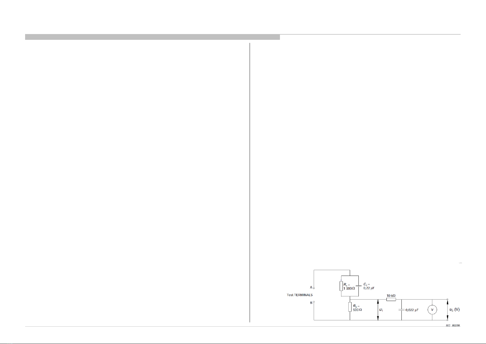
Leakagecurrent can be measured by V: Voltmeteror oscilloscope (r.m.s. or
peakreading)
Stabilized power supply instrument and isolated voltage transformer:
Use too much currentcapacity and isolated voltage transformerdoes not
need to use stabilized powersupply equipment.
Specificationof RMS volt meter: Input resistance> 1 Mohm, Input
capacitance< 200 pF, Frequency range: 15 Hz – 1MHz . Refer Figure 1.
Isolated type volt -meter (FLUKE 8921A etc *1)
*1 Not use FLUKE 8920A that connectedto protective earth by diode
# Leakage current of measurement instrument is less than 10μArms when
undertest equipmentAC plug is opened
# Set up the following conditionand turn on the set. Applied voltage:
Nominal input voltage (Description on Nameplate)
# Measure the leakagecurrent betweenone phaseconductorand neutral
for terminal 1 and terminal
2. Read rms value, and then calculate to peak value PEAK VALUE =√2
RMS VALUE
Comply with the following requirement
Class II equipment (2-pin plug): for each terminal, the worst value of
measurementmust not exceed AC 283uA peak).
Note: including AC adaptor,AC adaptor/DC operated unit combination
Note:Productswhich are always used in touch with human body:141uA
(peak)
Note:As for productsdestinedfor SoutheastAsia (Rod Antennais
accessory.Or it is packedwith a product.),the worst value must not exceed
AC 141uA (peak).
Figure 1 – Measuring network
for Leakage Current