Sony Walkman MZ-G755 User manual

1
SERVICE MANUAL
FM/AM PORTABLE MINIDISC RECORDER
ModelNameUsingSimilarMechanism MZ-G750/R700
Mechanism Type MT-MZR700-172
OpticalPick-upName LCX-4R
MD recorder
Audio playing system
MiniDisc digital audio system
Laser diode properties
Material: GaAlAs MQW
Wavelength: λ= 790 nm
Emission duration: continuous
Laser output: less than 44.6 µW
(This output is the value measured at a
distance of 200 mm from the lens surface
on the optical pick-up block with 7 mm
aperture.)
Recording and playback time
When using MDW-80
Maximum 160 min. in monaural
Maximum 320 min. in stereo
Revolutions
350 rpm to 2,800 rpm (CLV)
Error correction
ACIRC (Advanced Cross Interleave Reed
Solomon Code)
Sampling frequency
44.1 kHz
Sampling rate converter
Input: 32 kHz/44.1 kHz/48 kHz
Coding
ATRAC (Adaptive TRansform Acoustic
Coding)
ATRAC3-LP2
ATRAC3-LP4
SPECIFICATIONS
Modulation system
EFM (Eight to Fourteen Modulation)
Number of channels
2 stereo channels
1 monaural channel
Frequency response
20 to 20,000 Hz ± 3 dB
Wow and Flutter
Below measurable limit
Inputs
Microphone: stereo mini-jack, minimum
input level 0.35 mV
Line in: stereo mini-jack, minimum input
level 49 mV
Optical (Digital) in: optical (digital) mini-
jack
Outputs
i: stereo mini-jack, maximum output level
5 mW + 5 mW, load impedance 16 ohm
Radio
Frequency range
AM: 531-1,602 kHz
FM: 87.5-108.0 MHz
General
Power requirements
SonyAC PowerAdaptor (supplied*)
connected at the DC IN 3 V jack:
230 V AC, 50/60 Hz (AEP, FR, CET
model)
240 V AC, 50 Hz (Australian model)
230-240 V AC, 50 Hz (UK, HK model)
110/220 V AC, 60 Hz (Korean model)
100-240 V AC, 50/60 Hz (E, JE model)
Nickel cadmium rechargeable battery
NC-WMAA (supplied)
LR6 (size AA) alkaline battery (not
supplied)
*) Except for Korean model
•Abbreviation
FR : French model
CET : East European & CIS model
JE : Tourist model
HK : Hong Kong model
– Continued on next page –
US and foreign patents licensed
from Dolby Laboratories.
Ver 1.0 2001. 01Ver 1.0 2002. 04
Sony Corporation
Personal Audio Company
Published by Sony Engineering Corporation
9-873-965-01
2002D0400-1
© 2002. 04
AEP Model
UK Model
E Model
Australian Model
Tourist Model
MZ-G755
The CE mark is valid
only for products
marketed in the
European Union.

2
Flexible Circuit Board Repairing
•Keep the temperature of the soldering iron around 270°C
during repairing.
•Do not touch the soldering iron on the same conductor of the
circuit board (within 3 times).
•Be careful not to apply force on the conductor when soldering
or unsoldering.
Notes on chip component replacement
•Never reuse a disconnected chip component.
•Notice that the minus side of a tantalum capacitor may be
damaged by heat.
CAUTION
Use of controls or adjustments or performance of procedures
other than those specified herein may result in hazardous
radiation exposure.
Battery operation time
Battery life
When recording1) 2) (Unit: approx.hours) (JEITA3))
Batteries Stereo LP2 LP4
NC-WMAA Nickel Cadmium 4 6 7.5
rechargeable battery4)
LR6 (SG) Sony alkaline dry 96) 136) 166)
battery5)
When playing1) (Unit: approx.hours) (JEITA3))
Batteries Stereo LP2 LP4
NC-WMAA Nickel Cadmium 11.5 14 16
rechargeable battery4)
LR6 (SG) Sony alkaline dry 36 42 48
battery5)
When using the radio1) (JEITA3))
Batteries Approx. hours
NC-WMAA Nickel Cadmium rechargeable 9.5
battery4)
LR6 (SG) Sony alkaline dry battery5) 28.5
1) The battery life may be shorter due to operating conditions, the
temperature of the location, and varieties of batteries.
2) When you record, use a fully charged rechargeable battery.
3) Measured value by the standard of JEITA (Japan Electronics and
Information Technology Industries Association).
4) When using a 100% fully charged rechargeable battery.
5) When using a Sony LR6 (SG) “STAMINA” alkaline dry battery
(produced in Japan).
6) Recording time may differ according to the alkaline batteries.
Dimensions
Approx. 81 ×28.1 ×74.4 mm (w/h/d)
without projections.
Mass
Approx. 118 g the recorder only
Supplied accessories
NC-WMAA nickel cadmium rechargeable battery (1)
AC power adaptor (Except for Korean model) (1)
AC plug adaptor (Tourist model only) (1)
Headphones/earphones with a remote control (1)
Optical cable (1)
Rechargeable battery carrying case (1)
Carrying pouch/carrying case with a belt clip (1)
Design and specifications are subject to change
without notice.
SAFETY-RELATED COMPONENT WARNING!!
COMPONENTS IDENTIFIED BY MARK 0OR DOTTED LINE
WITH MARK 0ON THE SCHEMATIC DIAGRAMS AND IN
THE PARTS LIST ARE CRITICAL TO SAFE OPERATION.
REPLACE THESE COMPONENTS WITH SONY PARTS WHOSE
PART NUMBERS APPEAR AS SHOWN IN THIS MANUAL
OR IN SUPPLEMENTS PUBLISHED BY SONY.
ATTENTION AU COMPOSANT AYANT RAPPORT
À LA SÉCURITÉ!!
LES COMPOSANTS IDENTIFIÉS PAR UNE MARQUE 0SUR
LES DIAGRAMMES SCHÉMATIQUES ET LA LISTE DES
PIÈCES SONT CRITIQUES POUR LA SÉCURITÉ DE
FONCTIONNEMENT. NE REMPLACER CES COMPOSANTS
QUE PAR DES PIÈCES SONY DONT LES NUMÉROS SONT
DONNÉS DANS CE MANUEL OU DANS LES SUPPLÉMENTS
PUBLIÉS PAR SONY.
MZ-G755

3
1. SERVICING NOTE......................................................... 4
2. GENERAL
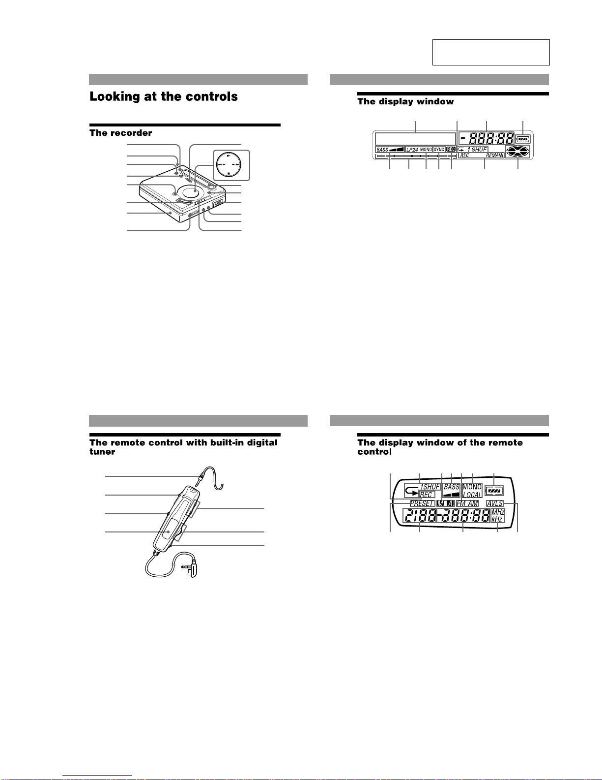
Looking at the controls ....................................................... 5
3. DISASSEMBLY
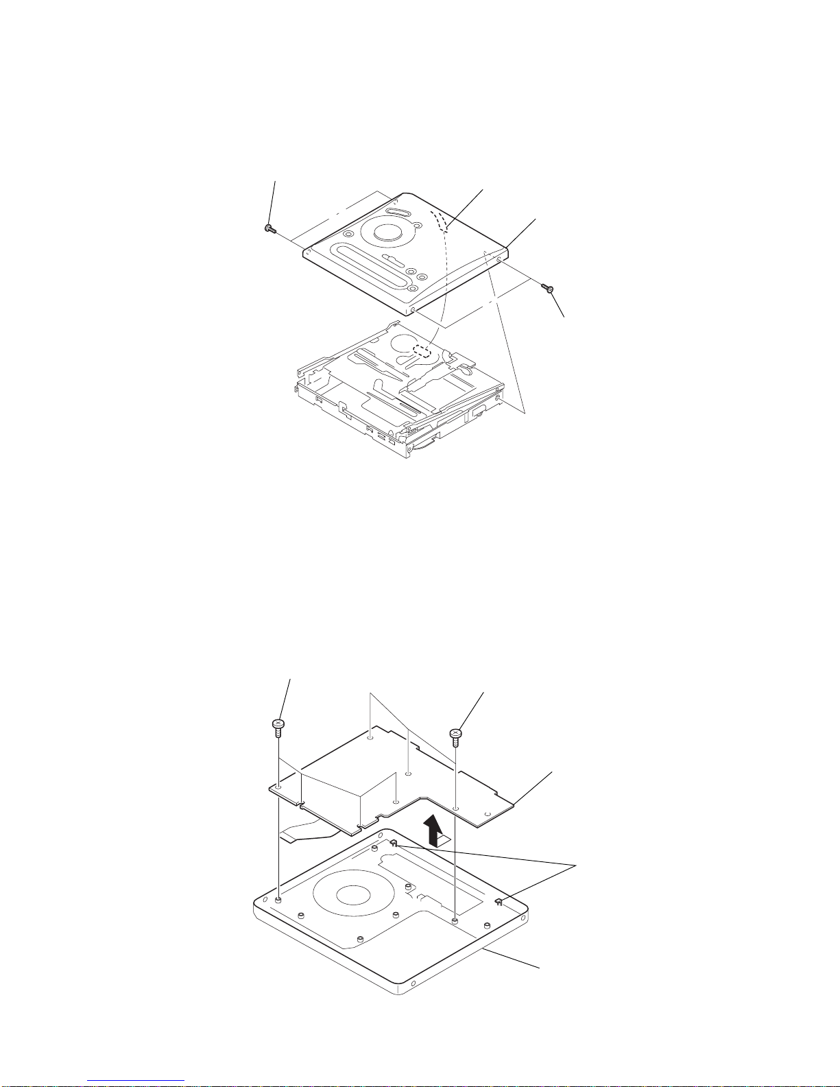
3-1. Bottom Panel Assy .............................................................. 6
3-2. Upper Panel Assy ................................................................ 7
3-3. LCD Module ....................................................................... 7
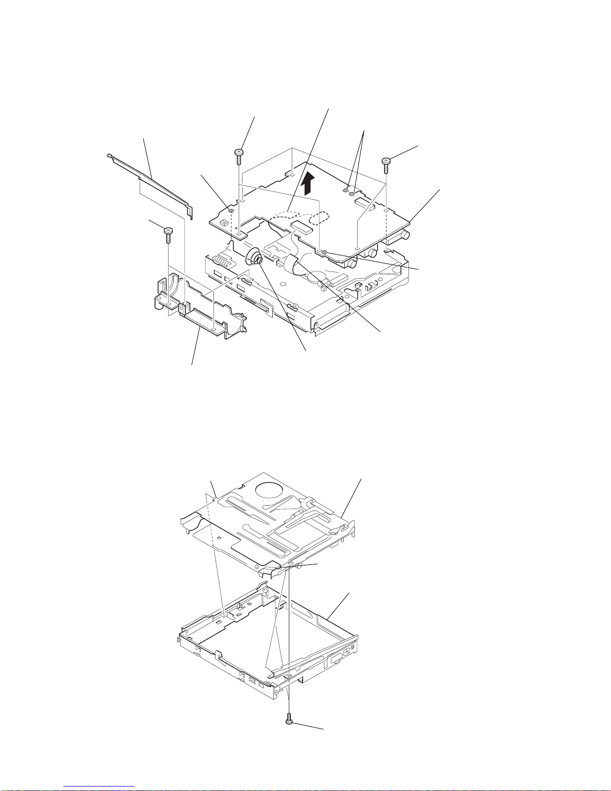
3-4. Main Board ......................................................................... 8
3-5. MD Mechanism Deck .........................................................8
3-6. OP Service Assy.................................................................. 9
3-7. Holder Assy......................................................................... 9
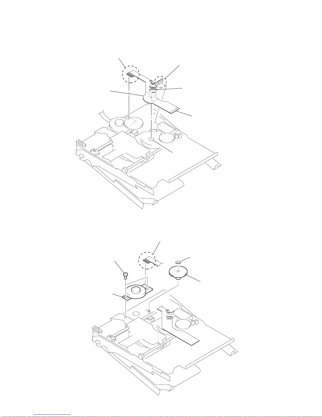
3-8. Motor Flexible Board ........................................................ 10
3-9. DC Motor (M602) .............................................................10
3-10. DC Motor (M601), DC Motor (M603) ............................. 11
4. TEST MODE
4-1. Outline ............................................................................... 12
4-2. Setting Method of Test Mode ............................................ 12
4-3. Operation in Setting the Test Mode................................... 12
4-4. Releasing the Test Mode ................................................... 12
4-5. Configuration of Test Mode .............................................. 13
4-6. Manual Mode .................................................................... 13
4-7. Overall Adjustment Mode ................................................. 14
4-8. Self-diagnosis Result Display Mode ................................. 14
4-9. Result the Error Display Code .......................................... 15
4-10. Sound Skip Check Result Display Mode .......................... 16
4-11. Key Check Mode............................................................... 16
TABLE OF CONTENTS
5. ELECTRICAL ADJUSTMENTS
5-1. Outline ............................................................................... 18
5-2. Precautions for Adjustment ............................................... 18
5-3. Adjustment Sequence ........................................................ 18
5-4. NV Reset ........................................................................... 18
5-5. Power Supply ManualAdjustment.................................... 19
5-6. Temperature Correction..................................................... 20
5-7. Laser Power Check ........................................................... 20
5-8. Overall Adjustment Mode ................................................. 21
6. DIAGRAMS
6-1. IC Pin Descriptions .......................................................... 24
6-2. Block Diagram – Servo Section – ..................................... 31
6-3. Block Diagram – Audio Section – .................................... 32
6-4. Block Diagram – System Control/Power Section – .......... 33
6-5. Printed Wiring Board – Main Section – ............................34
6-6. Schematic Diagram – Main Section (1/3) – ...................... 37
6-7. Schematic Diagram – Main Section (2/3) – ...................... 38
6-8. Schematic Diagram – Main Section (3/3) – ...................... 39
6-9. IC Block Diagrams............................................................ 40
7. EXPLODED VIEWS
7-1. Panel Section ..................................................................... 43
7-2. Chassis Section ................................................................. 44
7-3. MD Mechanism Deck Section ..........................................45
8. ELECTRICAL PARTS LIST...................................... 46
MZ-G755

4
MZ-G755 SECTION 1
SERVICING NOTE
NOTES ON HANDLING THE OPTICAL PICK-UP
BLOCK OR BASE UNIT
The laser diode in the optical pick-up block may suffer electro-
static break-down because of the potential difference generated
by the charged electrostatic load, etc. on clothing and the human
body.
During repair, pay attention to electrostatic break-down and also
use the procedure in the printed matter which is included in the
repair parts.
The flexible board is easily damaged and should be handled with
care.
NOTES ON LASER DIODE EMISSION CHECK
Never look into the laser diode emission from right above when
checking it for adjustment. It is feared that you will lose your sight.
NOTES ON HANDLING THE OPTICAL PICK-UP BLOCK
(LCX-4R)
The laser diode in the optical pick-up block may suffer electro-
static break-down easily. When handling it, perform soldering
bridge to the laser-tap on the flexible board. Also perform mea-
sures against electrostatic break-down sufficiently before the op-
eration. The flexible board is easily damaged and should be handled
with care.
OPTICAL PICK-UP FLEXIBLE BOARD
•In performing the repair with the power supplied to the set,
removing the MAIN board causes the set to be disabled.
In such a case, fix a convex part of the open/close detect switch
(S806 on MAIN board) with a tape in advance.
Handle the FLEXIBLE board (over write head) with care, as it
has been soldered directly to the MAIN board.
In repairing the component side of MAIN board, connect the
FLEXIBLE board (over write head) and the MAIN board with
the lead wires in advance. (See page 8)
•Replacement of CDX2674-204GA (IC801) used in this set
requires a special tool.
•On the set having the microcomputer version 1.000, some
adjusted values were set in the manual mode at the shipment,
but these data will be cleared when the NV is reset. Therefore,
on the set having the microcomputer version 1.000, change the
adjusted values following the Change of Adjusted Values
immediately after the NV was reset. (See page 18)
•If the nonvolatile memory was replaced on the set, the modified
program data must be written to the nonvolatile memory. In such
a case, write the modified data that meets the microcomputer
version following the patch data rewriting procedure at the
replacement of nonvolatile memory. (See page 23)
laser-tap
S806 MAIN board
FLEXIBLE board
(Over write head)
Tape
upper panel assy

5
MZ-G755
SECTION 2
GENERAL This section is extracted from
instruction manual.
6
See pages in ( ) for more details.
A
REC MODE button (25)
B
OPEN button (11)
C
T MARK button (51)
D
END SEARCH button
(14)(55)
E
X(pause) button
(15)(18)(32)(55)
F
VOL +/– button (17)(55)
The VOL + button has a
tactile dot.
G
DC IN 3V jack (10)(13)
H
i(headphones/earphones)
jack (11)(42)
I
REC (record) switch
(14)(24)
J
<SELECT,button
(27)(36)(49)
N(play) button (14)(17)
The Nbutton has a tactile
dot.
./>(search/AMS)
button (15)(18)(52)(55)
CHARGE/x(stop) button
(10)(14)(17)(26)(49)
K
Display window (27)(36)
L
MENU/ENTER button
(26)(36)(48)
M
Battery compartment (10)
N
LINE IN (OPTICAL) jack
(13)(24)
O
MIC (PLUG IN POWER)
jack (29)
There is a tactile dot beside
the MIC (PLUG IN POWER)
jack.
P
HOLD switch (11)(41)
SELECT
CHARGE
A
B
C
E
G
F
H
J
K
L
M
O
P
N
I
D
7
A
Character information
display (34)(39)
Displays the disc and track
names, error messages, track
numbers, etc.
B
Play mode indication (36)
Shows the play mode of the
MD.
C
Time display
D
Battery indication (58)
Shows approximate battery
condition.
E
Mega bass indication (38).
F
Level meter (33)
Shows the volume of the
MD being played or
recorded.
G
Recording mode (LP2/LP4/
MONO) indication (25)
H
SYNC (synchro-recording)
indication
I
REC indication (14)
Lights up while recording.
When flashing, the recorder
is in record standby mode.
J
REC REMAIN/REMAIN
(remaining time/tracks)
indication (34)(39)
Lights up along with the
remaining time of the track,
the remaining time of the
MD, or the remaining
number of tracks.
K
Disc indication
Shows that the disc is
rotating for recording,
playing or editing an MD.
I
EFGHK
J
AB D
C
8
A
Headphones/earphones
Can be replaced with
optional headphones/
earphones.
B
HOLD switch (11)(41)
Slide to lock the controls of
the remote control.
C
RADIO ON/BAND button
(20)(44)
FM MODE button (21)
D
Display window (44)
E
VOL +/– buttons (17)(20)
F
Jog lever
X(pause)/MODE (18)(44)
>N (AMS/search,
play)/F+ button (17)(20)(45)
.(AMS/search)/F–
button(18)(20)(45)
G
x(stop)/RADIO OFF
button (17)(21)(47)
B
A
C
D
E
F
G
9
A
REC indication (14)
Lights up while recording.
When flashing, the recorder
is in record standby mode.
B
Play mode indication (36)
Shows the play mode of the
MD.
C
Manual/Auto indication
D
Mega Bass indication (38)
E
FM/AM indication (44)
F
MONO (monaural)/LOCAL
indication
G
Battery indication
H
PRESET indication (44)
Lights up while preset radio
station is turned on.
I
Number display
Displaysthepresetnumbers,
track numbers, etc.
J
Time/Frequency display
K
MHz/kHz indication (44)
MHz lights up when FM
station is turned on and kHz
lights up when AM station is
turned on.
L
AVLS indication (40)
A
HI J KL
BCDEFG

6
MZ-G755
Note : This set can be disassemble according to the following sequence.
SECTION 3
DISASSEMBLY
3-1. BOTTOM PANEL ASSY
Note : Follow the disassembly procedure in the numerical order given.
6
bottom panel assy
4
claw
1
5
2
MI screws (1.4x2.0
)
3
MI screws (1.4x2.0)
3-1. BOTTOM PANEL ASSY
(Page 6)
3-2. UPPER PANEL ASSY
(Page 7)
3-4. MAIN BOARD
(Page 8)
3-6. OP SERVICE ASSY
(Page 9)
SET
3-5. MD MECHANISM DECK
(Page 8)
3-10. DC MOTOR (M601),
DC MOTOR (M603)
(Page 11)
3-8. MOTOR FLEXIBLE
BOARD
(Page 10)
3-3. LCD MODULE
(Page 7)
3-7. HOLDER ASSY
(Page 9) 3-9. DC MOTOR (M602)
(Page 10)

7
MZ-G755
3-3. LCD MODULE
1
screws (1.7x2.5)
4
LCD module
claws
upper panel (B) sub ass
y
2
screws (1.7x2.5)
3
3-2. UPPER PANEL ASSY
2
MI screws (1.4x2.0)
1
MI screws (1.4x2.0
)
3
upper panel assy
4
CN804

8
MZ-G755
3-5. MD MECHANISM DECK
2
set chassis assy
3
MD mechanism dec
k
boss
boss
1
MI screws (1.4x1.6)
3-4. MAIN BOARD
3
screws (M1.4x2)
6
Remove the solders.
7
9
Remove the solder.
q;
battery case assy
qs
battery coil spring
qd
MAIN board
qa
Remove
the solder.
4
screws (M1.7x3)
5
screws (M1.4x2)
1
CN502
2
arm
8
CN501

9
MZ-G755
3-7. HOLDER ASSY
3
Remove the holder assy to
direction of the arrow
B
.
1
Open the holder assy.
A
2
B
boss
3-6. OP SERVICE ASSY
4
rack spring (s)
6
thrust detent spring
3
precision pan screw
(M1.4)
5
precision pan screw (M1.4)
1
washer (0.8 - 2.5)
2
gear (SA)
8
Pull off the lead screw.
7
B
A
9
Opening the over write head
toward the direction
A
, remove the
OP service assy toward
the direction
B
.
Note: Do not open the entire assy
forcibly, when opening
the over write head.
over write head section

10
MZ-G755
4
two precision pan screws (M1.4)
5
DC moter (sled) (M602)
3
Remove four solders of
motor flexible board.
1
washer (0.8 - 2.5)
2
gear (SA)
3-9. DC MOTOR (M602)
2
Remove two solders of
DC motor (over write head up/down) (M603).
1
Remove four solders of
DC motor (sled) (M602).
3
Remove four solders of
DC motor (spindle) (M601).
DC motor (sled)
circular hole
5
motor flexible board
4
adhesive sheet
Note: Align a circular hole in the stripping paper
with a circular hole in the DC motor (sled),
when mounting the motor
flexible board.
3-8. MOTOR FLEXIBLE BOARD

11
MZ-G755
1
Remove six solders of
motor flexible board.
4
three precision pan
screws (M1.4)
qs
DC moter (over write head up/down)
(M603)
6
two precision pan screws (M1.4)
qa
gear chassis assy
0
screw
(M1.2
×
1.5)
9
gear (HA)
8
gear (HB)
7
washer (0.8 - 2.5)
2
washer (0.8 - 2.5)
3
gear (HC)
5
DC moter
(spindle)
(M601)
DC motor
(over write head up/down)
(M603)
gear chassis assy
gear (HA)
2.65 mm
Note: Press-fit the gear (HA) up to the
position of the DC motor (over write
head up/down) (M603) as shown
below.
3-10. DC MOTOR (M601), DC MOTOR (M603)

12
MZ-G755
2In the normal mode, turn on the [HOLD] switch. While press-
ing the [VOL --] key press the following order:
>t>t.t.t>t
.t> t.tXtX
SECTION 4
TEST MODE
4-3. Operation in Setting the Test Mode
•When the test mode becomes active, first the display check mode
is selected.
•Other mode can be selected from the display check mode.
•When the test mode is set, the LCD repeats the following dis-
play.
•When the Xkey is pressed and hold down, the display at that
time is held so that display can be checked.
Caution: On the set having the microcomputer version 1.000,
some adjusted values were set in the manual mode at
the shipment, but these data will be cleared when the
NV is reset. Therefore, on the set having the micro-
computer version 1.000, change the adjusted values
following the Change of Adjusted Values immediately
after the NV was reset (see page 18).
4-4. Releasing the Test Mode
For test mode set with the method 1:
Turn off the power and open the solder bridge on SL801 (TEST)
on the MAIN board.
Note: Remove the solders completely. Remaining could be shorted
with the chassis, etc.
For test mode set with the method 2:
Turn off the power.
Note: If electrical adjustment (see page 18) has not been finished
completely, always start in the test mode. (The set cannot
start in normal mode)
4-1. Outline
•This set provides the Overall adjustment mode that allows CD
(PB) and MO (REC/PB) disk to be automatically adjusted when
in the test mode. In this overall adjustment mode, the disc is
discriminate between CD and MO, and each adjustment is
automatically executed in order. If a fault is found, the system
displays its location. Also, the manual mode allows each
individual adjustment to be automatically adjusted.
•Operation in the test mode is performed with the set. A key
having no particular description in the text, indicates a set key.
•For the LCD display, the LCD on the set is shown.
4-2. Setting Method ofTest Mode
There are two different methods to set the test mode:
1Short SL801 (TEST) on the MAIN board with a solder bridge
(connect pin 3of IC801 to the ground). Then, turn on the
power.
MAIN BOARD (SIDE B)
C821
C815
X801
SL801
(TEST)
C809
R817
C807C808R806
C814
FB801
AP817
AP828
BASS
All lit
This set LCD display
SYNCMONOLP24 REC
REC DATE REMAIN
1 SHUFF PGM
AM
PM
F
e
88:88
00 5
All off
Microcomputer
version
display
Ver 1.300

13
MZ-G755
4-5. Configuration of Test Mode
4-6. Manual Mode
Mode to adjust or check the operation of the set by function.
Normally, the adjustment in this mode is not executed.
However, the Manual mode is used to clear the memory, power
supply adjustment, and laser power check before performing
automatic adjustments in the Overall Adjustment mode.
•Transition method in manual mode
1. Setting the test mode (see page 12).
2. Press the >or [VOL +] key activates the manual mode
where the LCD display as shown below.
3. During each test, the optical pick-up moves outward or in-
ward while the Nor .key is pressed for several sec-
onds respectively.
4. Each test item is assigned with a 3-digit item number;
100th place is a major item, 10th place is a medium item, and
unit place is a minor item.
The values adjusted in the test mode are written to the
nonvolatile memory (for the items where adjustment was
made).
Press the >or VOL +key.
Press the xkey.
Press the xkey.
Press the xkey.
Press the xkey.
Press the Nor REC key.
The key check quits, or open the upper panel.
Press the T MARK or ENTER key for several
seconds (about 3 seconds).
ENTER key
Test Mode (Display Check Mode)
Servo Adjustment
Manual Mode
Key Check Mode
Audio Adjustment
Power Supply Adjustment
OP Alignment Adjustment
Press the .or VOL – key.
Electrical Offset Adjustment
Overall Adjustment Mode
Sound Skip Check Result Display Mode
Self-diagnosis Result Display Mode
Power Supply Adjustment
Auto Item Feed
CD Overall Adjustment/
MO Overall Adjustment
00 0
Manual
This set LCD display
xkeyNkey
xkeyNkey
Major Item Switching
Minor Item Switching
Medium Item Switching
.key: Unit Place of item number
decrease.
VOL – key: 10th Place of item number
decrease.
VOL +key: 10th Place of item number
increase.
VOL – key: Decreases the
adjusted value.
VOL +key: Increases the
adjusted value.
VOL – key: 100th Place of item number
decrease.
VOL +key: 100th Place of item number
increase.
Nkey: Unit Place of item number
increase.
Xkey: When adjusted value is
chaged:
Adjusted value is written.
When adjusted value is
not changed:
That item is adjusted
automatically.
Adjusted Value Variation
Adjusted Value Write

14
MZ-G755
4-8. Self-diagnosis Result Display Mode
This set uses the self-diagnostic function system in which if an
error occurred during the recording or playing, the mechanism
control block and the power supply control block in the
microcomputer detect it and record its cause as history in the
nonvolatile memory.
By checking this history in the test mode, you can analyze a fault
and determine its location.
Total recording time is recorded as a guideline of how long the
optical pick-up has been used, and by comparing it with the total
recording time at the time when an error occurred in the self-
diagnosis result display mode, you can determine when the error
occurred.
Clear both self-diagnosis history data and total recording time, if
the optical pick-up was replaced.
•Self-diagnosis result display mode setting method
1. Setting the test mode (see page 12).
2. In the display check mode, press the [ENTER] key activates the
self-diagnosis result display mode where the LCD display as
shown below.
3. Then, each time the >key is pressed, LCD display descends
by one as shown below. Also, the LCD display ascends by one
when the .key is pressed.
If the [ENTER] key on set is pressed with this display, the LCD
switches to the simple display mode.
4. Quitthe self-diagnosis result display mode, and press the xkey
to return to the test mode (display check mode).
5. The display changes a shown below each time the
[ENTER] key on the set is pressed.
However in the power mode (item number 700’s), only the
item is displayed.
6. Quit the manual mode, and press the xkey to return to the
test mode (display check mode).
4-7. Overall Adjustment Mode
Mode to adjust the servo automatically in all items.
Normally, automatic adjustment is executed in this mode at the
repair.
For further information, refer to “Section 5 ElectricalAdjustments”
(see page 18).
This set LCD display
item number
adjustment value
address
• Address & Adjusted Value Display
0 113A4S1D
This set LCD display
item number
adjustment value
jitter value
• Jitter Value & AdjustedValue Display
0 110FEJ1D
This set LCD display
item number
adjustment value
block error value
• Block Error Value & AdjustedValue Display
0 11063B1D
This set LCD display
item number
adjustment value
ADIP error value
• ADIP Error Value & AdjustedValue Display
0 11072A1D
This set LCD display
item number
adjustment value
• Item Title Display
0 11LrefPw 1D
item title
This set LCD display
error display code
Total recording time when error occurred
0 XX1 0010
history
code
0 XX1
0 XXN
0 XXN1
0 XXN2
0 XXR_
XX
: Error code
: Total recording time

15
MZ-G755
• Description of indication history
History code number Description
1The first error
NThe last error
N1 One error before the last
N2 Two errors before the last
R_ Total recording time
4-9. Reset the Error Display Code
After servicing, reset the error display code.
•Setting method of reset the error display code
1. Setting the test mode (see page 12).
2. Press [ENTER] key activates the self-diagnosis result display
mode.
3. To reset the error display code, press the Xkey (2 times) when
the code is displayed (except “R_****”).
(All the data on the 1, N, N1 and N2 will be reset)
• Description of error indication codes
Problem Indication code Meaning of code Simple display Description
No error 00 No error --- No error
01 Illegal access target Adrs Attempt to access an abnormal address
address was specified
Servo system error 02 High temperature Temp High temperature
03 Focus error Fcus Disordered focus
04 Spindle error Spdl Abnormal rotation of disc
TOC error 11 TOC error TOC Faulty TOC contents
12 Data reading error Data Data could not be read at SYNC
Power supply system error 22 Low battery LBat Momentary interruption detected
31 Offset error Ofst Offset error
32 Focus error ABCD Focus error
ABCD offset error ABCD offset error
Offset system error 33 Tracking error TE Tracking error
Offset error Offset error
34 X1 tracking error X1TE X1 tracking error
Offset error Offset error

16
MZ-G755
4-11. Key Check Mode
This set can check if the set and remote commander function nor-
mally.
• Setting method of key check mode
1. Setting the test mode (see page 12).
2. Press the [T MARK] key for several seconds (about 3 seconds)
activates the key check mode. (At the last two digits,AD value
of remote commander key line is displayed in hexadecimal)
3. When each key on the set and on remote commander is pressed,
its name is displayed on the LCD. (The operated position is
displayed for 4 seconds after the slide switch is operated. If
any other key is pressed during this display, the remote com-
mander LCD switches to its name display)
Example1: When >key on the set is pressed:
Example2: When N>key on the remote commander is
pressed:
4-10. Sound Skip Check Result Display Mode
This set can display the count of errors that occurred during the
recording/playing for checking.
•Setting method of sound skip check result display
mode
1. Set the test mode (see page 12).
2. Press the Nkey or [REC] key, and the playing or recording
sound skip result display mode becomes active respectively
where the LCD displays the following.
3. When the Nkey is pressed, total error count is displayed on
the LCD, and each time the >key is pressed, the display
item moves down by one as shown below.Also, if the .key
is pressed, the display item moves up by one, then if the [REC]
key is pressed, the display in the record mode appears.
When the [REC] key is pressed, total error count is displayed
on the LCD, and each time the >key is pressed, the display
item moves down by one as shown below.Also, if the .key
is pressed, the display item moves up by one, then if
the Nkey is pressed, the display in the play mode appears.
This set LCD display
Total count record
system errors (hex.)
0 00P R
Total count of play
system errors (hex.)
• Cause of sound skip error
Cause of error Description of error
EIB Sound error correction error
Play Stat Decoder status error
Adrs Address access error
BEmp Buffer is empty
BOvr Buffer is full, and sounds were
dumped
Record Bful Buffer capacity becomes less,
and forcible writing occurred
Rtry Retry times over
4. To quit the sound skip check result display mode and to return
to the test mode (display check mode), press the xkey.
0 00P R
P R
0 00EIB
0 00Stat
0 00Adre
0 00BEmp
0 00######
######
0 00P R
0 00BOvr
0 00Bful
0 00Rtry
0 00######
Playing sound skip
result display
Recording sound skip
result display
: Total play/record errors (hex.)
: Counter of sound skip check each item (hex.)
: 6-digit address where sound was skipped last (hex.)
This set LCD display
0 00
: AD value of the remote commander key
(hexadecimal OO to FF)
This set LCD display
0 00FF
: AD value of the remote commander key
(hexadecimal OO to FF)
This set LCD display
0 00rPLAY
: AD value of the remote commander key
(hexadecimal OO to FF)

17
MZ-G755
4. When all the keys on the set and on the remote commander are
considered as OK, the following displays are shown for 4 sec-
onds.
Example1: When the keys on the set are considered as OK:
Example2: When the keys on the remote commander are con-
sidered as OK:
5. When all keys were checked or if the upper panel is opened,
the key check mode quits and the test mode (display check
mode) comes back.
This set LCD display
0 00SET OK
: AD value of the remote commander key
(hexadecimal OO to FF)
This set LCD display
0 00RMC OK
: AD value of the remote commander key
(hexadecimal OO to FF)

18
MZ-G755
•Setting method of NV reset
1. Select the manual mode of the test mode, and set item number
021NV Reset (see page 13).
2. Press the Xkey.
3. Press the Xkey once more.
4. Press the xkey to quit the manual mode, and activate the
test mode (display check mode).
•Change of adjusted values
1. Item numbers in which the adjusted values are to be modified
Item number 832
Item number 862
Item number 871
Item number 872
2. Adjusted values modifying procedure
1) Select the manual mode of the test mode, and set item number
832 (see page 13).
2) Adjust with the [VOL +] key (adjusted value up) or [VOL --]
key (adjusted value down) so that the adjusted value becomes
E4.
SECTION 5
ELECTRICAL ADJUSTMENTS
5-1. Outline
•In this set, automatic adjustment of CD and MO can be per-
formed by entering the test mode (see page 12).
However, before starting automatic adjustment, the memory
clear, power supply adjustment, and laser power check must be
performed in the manual mode.
•Akey having no particular description in the text, indicates a
set key.
•For the LCD display, the LCD display on the set is shown.
5-2. Precautions for Adjustment
1. Adjustment must be done in the test mode only.
After adjusting, release the test mode.
2. Use the following tools and measuring instruments.
•CD disc TDYS-1 (Check MD disc)
(Part No. : 4-963-646-01)
•MO disk (SONY MD disc available on the market)
•Digital voltmeter
•Laser power meter LPM-8001
(Part No. : J-2501-046-A)
•Thermometer (using the Temperature Correction)
3. Unless specified otherwise, supply DC 3V from the DC IN
3V jack (J601).
4. Switch position
HOLD switch ............................................... OFF
5-3. Adjustment Sequence
5-4. NV Reset
Caution: In this set, certain adjustment values are set in the manual
mode at the factory.
NV reset will cause data to be cleared.
So, the adjustment values should be set again just after
NV reset is made.
1. NV Reset (Memory clear)
2. Power Supply Manual Adjustment
3. Temperature Correction (item number: 014)
4. Laser Power Check
5. Electrical Offset Adjustment
Caution: This adjustment must be made with
no disc loaded.
6. CD Overall Adjustment
7. MO Overall Adjustment
Manual Mode
Manual Mode
Manual Mode
Overall Mode
Overall Mode
This set LCD display
0 21ResNV CC
This set LCD display
0 21Res OK?
This set LCD display
0 21Res
0 21Reset!
NV reset (after several seconds)
This set LCD display
8 32Pw-T W
: Adjusted value

19
MZ-G755
•Adjustment method of Vc PWM duty (L)
(item number: 762)
1. Connect a digital voltmeter to the TP901 (VC) on the MAIN
board, and adjust [VOL +] key (voltage up) or [VOL --] key
(voltage down) so that the voltage becomes 2.50 ± 0.01V.
2. Press the Xkey to write the adjusted value.
(The item number changes to 763 when Xkey is pressed)
Adjustment and Connection Location:MAIN board
(see page 21)
•Adjustment method of Vc PWM duty (H)
(item number: 763)
1. Connect a digital voltmeter to the TP901 (VC) on the MAIN
board, and adjust [VOL +] key (voltage up) or [VOL --] key
(voltage down) so that the voltage becomes 2.50 ± 0.01V.
2. Press the Xkey to write the adjusted value.
(The item number changes to 764 when Xkey is pressed)
Adjustment and Connection Location:MAIN board
(see page 21)
•Adjustment method of Vl PWM duty
(item number: 764)
3) Press the Xkey to write the adjusted value.
4) Select the manual mode of the test mode, and set item number
862 (see page 13).
5) Adjust with the [VOL +] key (adjusted value up) or [VOL --]
key (adjusted value down) so that the adjusted value becomes
01.
6) Press the Xkey to write the adjusted value.
7) Select the manual mode of the test mode, and set item number
871 (see page 13).
8) Adjust with the [VOL +] key (adjusted value up) or [VOL --]
key (adjusted value down) so that the adjusted value becomes
20.
9) Press the Xkey to write the adjusted value.
10) Select the manual mode of the test mode, and set item number
872 (see page 13).
11) Adjust with the [VOL +] key (adjusted value up) or [VOL --]
key (adjusted value down) so that the adjusted value becomes
39.
12) Press the Xkey to write the adjusted value.
5-5. Power Supply Manual Adjustment
•Adjustment sequence
Adjustment must be done with the following steps.
•Setting method of power supply manual adjustment
1. Make sure that the power supply voltage is 3V.
2. Set the test mode (see page 12).
3. Press the .or [VOL --] key to activate the overall adjustment
mode.
4. Pressthe [END SEARCH] key. (the [END SEARCH] key causes
the item number to be switched to 762.)
This set LCD display
8 62V1dat
: Adjusted value
This set LCD display
8 71V5num
: Adjusted value
This set LCD display
8 72V5dat
: Adjusted value
2. Vc PWM Duty (H) adjustment (item number 763)
3. Vl PWM Duty adjustment (item number 764)
1. Vc PWM Duty (L) adjustment (item number 762)
This set LCD display
0 00Assy 00
This set LCD display
7 62VclPWM
: Adjusted value
digital
voltmeter
MAIN board
TP901 (VC)
TP912 (GND)
This set LCD display
7 63VchPWM
: Adjusted value
digital
voltmeter
MAIN board
TP901 (VC)
TP912 (GND)
This set LCD display
7 64Vl PWM
: Adjusted value

20
MZ-G755
2. Press the .key continuously until the optical pick-up
moves to the most inward track.
3. Open the cover and set the laser power meter on the objective
lens of the optical pick-up.
4. Press the Nkey, and set the laser MO read adjustment mode
(item number 011).
5. Check that the laser power meter reading is 0.81 ± 0.08 mW.
6. Check that the voltage both ends (TP (+) andTP (–)) of resistor
R521 at this time is below 44 mV.
7. Press the Nkey, and set the laser CD read adjustment
mode (item number 012).
8. Check that the laser power meter reading is 0.97 ± 0.10 mW.
9. Check that the voltage both ends (TP (+) andTP (–)) of resistor
R521 at this time is below 44 mV.
10. Press the Nkey, and set the laser MO write adjustment mode
(item number 013).
11. Check that the laser power meter reading is 4.95 ± 0.50 mW.
12. Check that the voltage both ends (TP (+) andTP (–)) of resistor
R521 at this time is below 80 mV.
13. Press the xkey to quit the manual mode, and activate the
test mode (display check mode).
Checking and Connection Location: MAIN board (see page 21)
1. Connect a digital voltmeter to the TP902 (VL) on the MAIN
board, and adjust [VOL +] key (voltage up) or [VOL --] key
(voltage down) so that the voltage becomes 2.30 ± 0.01V.
2. When press the Xkey to write the adjusted value, LCD dis-
plays as follows and power supply manual adjustment has com-
pleted.
Adjustment and Connection Location:MAIN board
(see page 21)
5-6.Temperature Correction
•Adjustment method of temperature correction
1. Select the manual mode of test mode, and set the mode num-
ber 014 (see page 13).
2. Measure the ambient temperature.
3. Adjust with [VOL +], [VOL --] key so that the adjusted value
(hexadecimal value) becomes the ambient temperature.
(Initial value: 14h = 20 °C,Adjusting range: 80h to 7fh (–128
°C to +127 °C)
4. Press the Xkey to write the adjusted value.
5-7. Laser Power Check
Connection :
Checking Method :
1. Select the manual mode of test mode (see page 13), and set the
laser power adjusting mode (item number 010).
digital
voltmeter
MAIN board
TP902 (VL)
TP912 (GND)
This set LCD display
0 00ADJ OK
This set LCD display
0 14SetTmp
: Adjusted value
digital
voltmeter
MAIN board
TP (+)
TP (–)
laser
power mete
r
Optical pick-up
objective lens
This set LCD display
0 10Laser
This set LCD display
0 11LrefPw
: Adjusted value
This set LCD display
0 12HrefPw
: Adjusted value
This set LCD display
0 13WritPw
: Adjusted value
Other manuals for Walkman MZ-G755
2
Table of contents
Other Sony Mini Disc Recorder manuals

Sony
Sony MZ-N10 Guide

Sony
Sony MD Walkman MZ-R5ST User manual

Sony
Sony Walkman MZ-R900DPC User manual

Sony
Sony MD Walkamn MZ-R2 User manual

Sony
Sony MDS-302 - Hi-fi Mini Disc User manual

Sony
Sony MZ-1 User manual

Sony
Sony MDS-JB940 User manual

Sony
Sony MDM-X4 User manual

Sony
Sony MZ-B100 - Minidisc Business Product Recorder User manual

Sony
Sony 158MDXC800 User manual