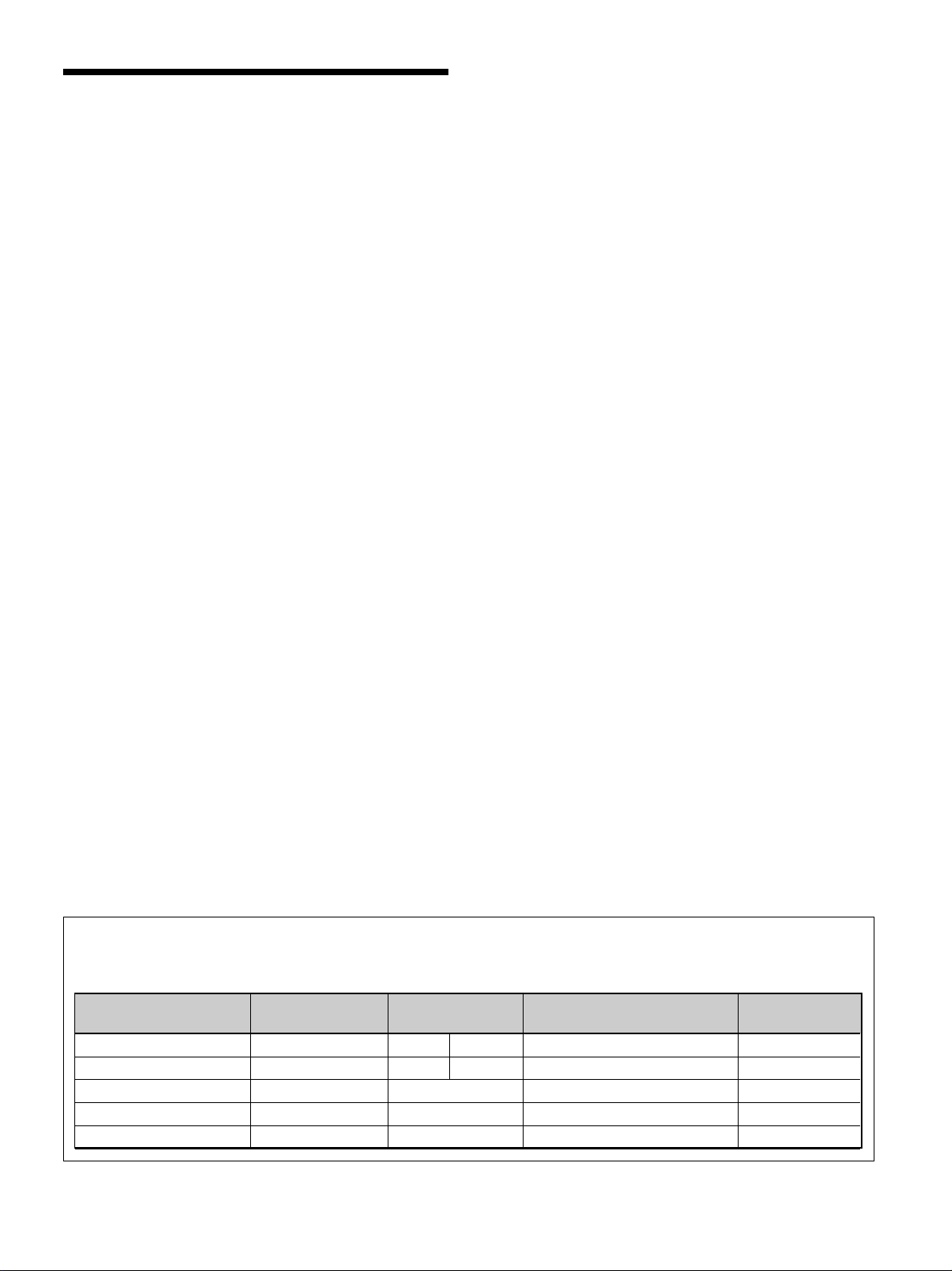
Sony PFM-510A1WE User manual

3-867-473-01 (1)
1999 by Sony Corporation
Operating Instructions
Mode d’emploi
Bedienungsanleitung
Manual de instrucciones
Istruzioni per l’uso
GB
FR
DE
ES
IT
この取扱説明書には、事故を防ぐための重要な注意事項と製品の取り扱
いかたを示しています。この取扱説明書をよくお読みのうえ、製品を安
全にお使いください。お読みになったあとは、いつでも見られるところ
に必ず保管してください。
お買い上げいただきありがとうございます。
電気製品は安全のための注意事項を守らないと、
火災や人身事故になることがあります。
取扱説明書
PFM-510A1WU
PFM-510A1WE
PFM-510A1WJ
Flat Panel Monitor
JP
PFM-510A1WU/510A1WE/510A1WJ

2(GB)
WARNING
Owner’s Record
The model and serial numbers are located on the rear.
Record the model and serial numbers in the spaces provided
below. Refer to these numbers whenever you call upon your
Sony dealer regarding this product.
Model No. Serial No.
To prevent fire or shock hazard, do not
expose the unit to rain or moisture.
For the customers in the U.S.A.
This equipment has been tested and found to comply with
the limits for a Class A digital device, pursuant to Part 15 of
the FCC Rules. These limits are designed to provide
reasonable protection against harmful interference when the
equipment is operated in a commercial environment. This
equipment generates, uses, and can radiate radio frequency
energy and, if not installed and used in accordance with the
instruction manual, may cause harmful interference to radio
communications. Operation of this equipment in a residential
area is likely to cause harmful interference in which case the
user will be required to correct the interference at his own
expense.
You are cautioned that any changes or modifications not
expressly approved in this manual could void your authority
to operate this equipment.
For the customers in Canada
This class A digital apparatus complies with Canadian ICES-
003.
For the customers in Europe
This is a Class A product. In a domestic environment, this
product may cause radio interference in which case the user
may be required to take adequate measures.
or
Clamps
For PFM-510A1WE users
THIS APPARATUS MUST BE EARTHED
IMPORTANT
The wires in this mains lead are coloured in accordance with
the following code:
Green-and-yellow : Earth
Blue : Neutral
Brown : Live
As the colours of the wires in the mains lead of this
apparatus may not correspond with the coloured markings
identifying the terminals in your plug proceed as follows:
The wire which is coloured green-and-yellow must be
connected to the terminal in the plug which is marked with
the letter E or by the safety earth symbol Ior coloured
green or green-and-yellow.
The wire which is coloured blue must be connected to the
terminal which is marked with the letter N or coloured black.
The wire which is coloured brown must be connected to the
terminal which is marked with the letter L or coloured red.
Voor de klanten in Nederland
Bij dit produkt zijn batterijen geleverd.
Wanneer deze leeg zijn, moet u ze niet
weggooien maar inleveren als KCA.
The socket-outlet should be installed near the equipment
and be easily accessible.
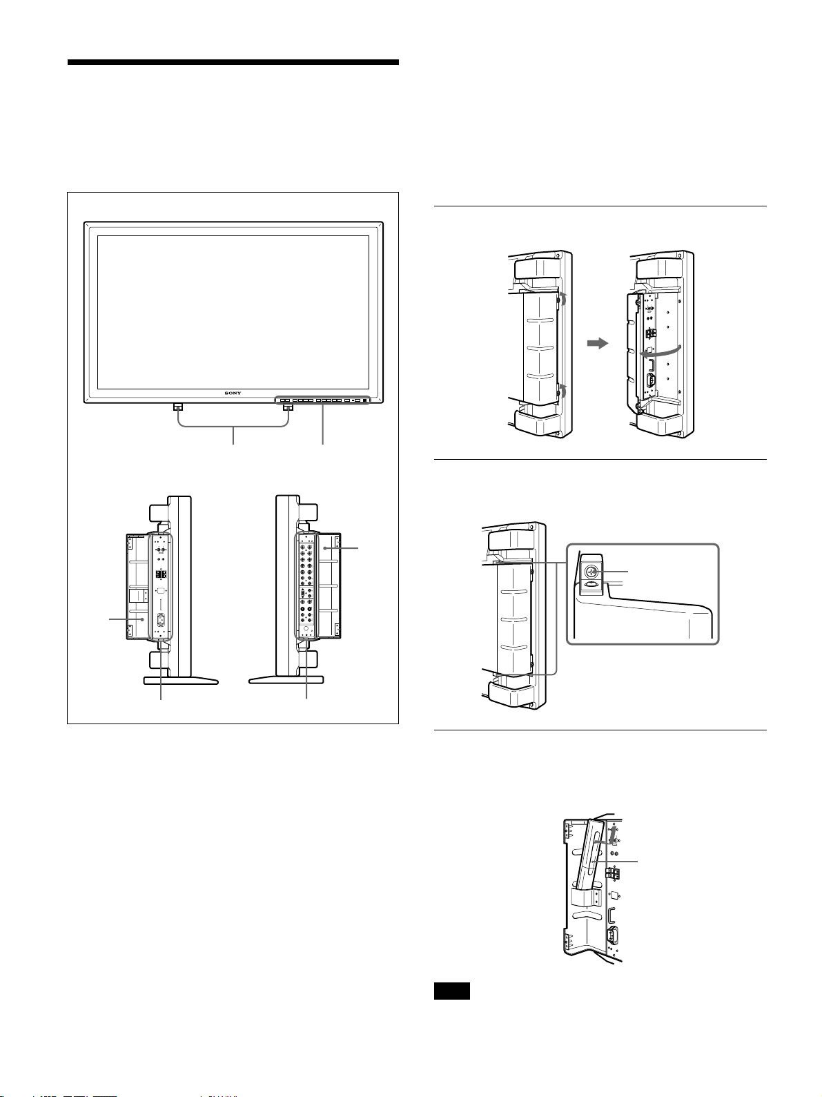
Note
When you connect a computer to this monitor,
attach the supplied ferrite cores. If you do not do
this, this monitor will not conform to mandatory
FCC/IC/CE (EN55022) standards.
Attaching the ferrite cores
Set the ferrite cores on the both ends of the AC
power cord. Close the lid tightly until the clamps
click.

3(GB)
English
GB
Table of Contents
Precautions ............................................................... 4 (GB)
Features..................................................................... 5 (GB)
Location and Function of Parts and Controls ....... 6 (GB)
Front / Sides ............................................................. 6 (GB)
Control Panel ........................................................... 7 (GB)
Right Connector Panel ............................................. 8 (GB)
Left Connector Panel ............................................. 10 (GB)
Remote Commander RM-921................................ 10 (GB)
Installation............................................................... 12 (GB)
Using the Retractable Feet ..................................... 12 (GB)
Caution................................................................... 13 (GB)
Connections............................................................ 14 (GB)
Connecting the AC Power Cord ............................ 14 (GB)
Connection Example.............................................. 14 (GB)
Using On-screen Menus ........................................ 16 (GB)
Operating Through Menus..................................... 16 (GB)
Menu Guide ........................................................... 16 (GB)
Watching the Picture.............................................. 20 (GB)
Switching the Picture ............................................. 20 (GB)
Input Signal and Monitor Status Information
Display .............................................................. 20 (GB)
Adjusting the Picture ............................................. 22 (GB)
Adjusting the Contrast, Brightness, Chroma,
and Phase .......................................................... 22 (GB)
Restoring the PIC CONTROL Menu Items to Original
Settings ............................................................. 22 (GB)
Resizing and Positioning the Picture ................... 23 (GB)
Resizing the Picture ............................................... 23 (GB)
Adjusting the Picture Position ............................... 23 (GB)
Restoring the Original Picture Size and Position.....
24 (GB)
Using the Memory .................................................. 25 (GB)
Storing the Current Condition................................ 25 (GB)
Calling Up the Stored Condition ........................... 25 (GB)
Selecting the On-screen Language ...................... 26 (GB)
Self-diagnosis Function......................................... 26 (GB)
Operating a Specific Monitor with the Remote
Commander ........................................................ 27 (GB)
Using the Other Remote Commander .................. 28 (GB)
Specifications ......................................................... 29 (GB)

4(GB)
Precautions
Precautions
On safety
•Operate the unit on 100 to 120 V AC or 220 to 240
V AC.
•The nameplate indicating operating voltage, power
consumption, etc. is located on the rear.
•Should any solid object or liquid fall into the cabinet,
unplug the unit and have it checked by qualified
personnel before operating it any further.
•Unplug the unit from the wall outlet if it is not to be
used for several days or more.
•To disconnect the AC power cord, pull it out by
grasping the plug. Never pull the cord itself.
•When the unit is installed on the floor, be sure to use
the retractable feet.
On installation
•Allow adequate air circulation to prevent internal
heat build-up. Do not place the unit on surfaces
(rugs, blankets, etc.) or near materials (curtains,
draperies) that may block the ventilation holes.
•Do not install the unit in a location near heat sources
such as radiators or air ducts, or in a place subject to
direct sunlight, excessive dust, mechanical vibration
or shock.
•When you install multiple equipment with the unit,
the following, such as Remote Commander’s
malfunction, noisy picture, noisy sound, may occur
depending on the position of the unit and other
equipment.
On PDP (Plasma Display Panel)
•There may be some tiny black points and/or bright
points on the PDP. These points are normal.
•Do not display a same still image on the screen for
long, consecutive time. Otherwise, the afterimage
may appear on a part of a panel. Use the screen saver
eventually to equalize the screen display.
On cleaning
To keep the unit looking brand-new, periodically
clean it with a mild detergent solution. Never use
strong solvents such as thinner or benzine, or abrasive
cleansers since these will damage the cabinet. As a
safety precaution, unplug the unit before cleaning it.
On repacking
Do not throw away the carton and packing materials.
They make an ideal container in which to transport the
unit. When shipping the unit to another location,
repack it as illustrated on the carton.
If you have any questions about this unit, contact your
authorized Sony dealer.

5(GB)
Features
Features
The PFM-510A1W series are 16:9 42-inch flat panel
monitor adopting the PDP (Plasma Display Panel) and
accepts various types of signals with the built-in scan
converter.
Improved image quality
The PDP achieves higher image quality with 1024 ×
1024 lines. This makes for finely-detailed HDTV and
PC images.
You can get greater brightness and contrast over
conventional monitors.
Internal high-performance scan converter
The monitor has a high performance scan converter.
Using a unique algorithm, the monitor processes
signals in a wide range of formats – Video, HDTV,
PC, etc.
Flexibility
An option slot is in place for future expansion.
The slot-in option adapter allows for quick and easy
system upgrades.
Other features
•Three sets of video inputs with audio inputs: one
composite video or Y/C inputs, one RGB input, and
one RGB/component input.
•Displays the HDTV signal with tri-level sync signal.
•Three dimensional comb filter for NTSC Y/C
separation.
•Line correlation comb filter for PAL Y/C separation.
•Automatic input signal detection with indication.
•Windows95/981) PnP (Plug and Play) compatible.
•Picture AGC function — this function automatically
adjusts and improves the contrast when a low
intensity signal is input.
•On-screen menu for various adjustments and settings
•On-screen display in five languages for user-friendly
access.
•Fine adjustment of image size and position
•Memory function for storage of up to five picture
settings.
•ID control
•Self-diagnosis function.
•Remote (RS-232C) connector (mini DIN 8-pin)
•Control-S connector
•Accepts infrared or wired Sony Remote
Commanders using SIRCS code.
•Vertical setup
Warning on power connection
Use a proper power cord for your local power supply.
United States, Continental United Kingdom, Ireland, Japan
Canada Europe Australia, New Zealand
Plug type VM0033B COX-07 636 — VM1296
Female end VM0113 COX-02 VM0310B VM0303B VM1313
Cord type SJT H05VV-F CEE (13) 53rd (O.C) HVCTF
Minimum cord set rating 13A/125V 10A/250V 10A/250V 10A/125V
Safety approval UL/CSA VDE VDE DENTORI
1) Windows95/98 is a registered trademark of the Microsoft Corporation.
.........................................................................................................................................................................................................

6(GB)
Screws
Remote
Commander
Location and Function
of Parts and Controls
Front / Sides
1Retractable feet
Use for setting the monitor on the floor.
For details on using the retractable feet, see “Using the
Retractable Feet” on page 12 (GB).
2Control panel
For details on the control panel, see “Control Panel” on
page 7 (GB).
3Left panel cover
Open it when using the left connector panel.
You can install the Remote Commander in the back of
this cover.
For details on opening the panel cover, see the right on this
page.
4Left connector panel
For details on the left connector panel, see “Left Connector
Panel” on page 10 (GB).
5Right connector panel
For details on the right connector panel, see “Right
Connector Panel” on page 8 (GB).
6Right panel cover
Open it when using the right connector panel.
For details on opening the panel cover, see the below on
this page.
To open the panel cover
Loosen the screws counterclockwise and open the cover.
To take off the panel cover
Loosen the screws as illustrated below and take off
the panel cover.
To install the Remote Commander in the
panel cover
Install the Remote Commander in the back of the left
panel cover as illustrated below.
Note
When housing the Remote Commander, make sure
that the top of the Remote Commander faces upward
and rear faces outside.
Left side
Front
Right side
Location and Function of Parts and Controls
4
3
12
5
6

7(GB)
Control Panel
1Remote control detector
Receives the beam from the Remote Commander.
21(standby) switch/1(standby) indicator
Press to turn the monitor on. Press again to go back to
the standby mode.
The 1(standby) indicator lights up in red in the
standby mode.
When the 1indicator flashes, see “Self-diagnosis
Function” on page 26 (GB).
3Power indicator
Lights up when the monitor is turned on.
4CTRL (control) button
To operate the buttons on the control panel, first press
this button. Then the buttons light up or flash that
show they can be operated. Press again to deactivate
them.
Note
The buttons (except for 1(standby) switch 2) on the
control panel do not function if you do not press the
CTRL button first.
5Y/C button
Select the signal input from the Y/C IN jack in the
LINE connectors.
6LINE button
Select the signal input from the VIDEO IN connector
in the LINE connectors.
7RGB2 button
Select the signal input from the RGB2 connectors.
8YUV button
Select the component signal input from the RGB1
connectors.
9RGB1 button
Select the RGB signal input from the RGB1
connectors.
0ENT (enter) button
Press to select the desired item in a menu.
qa M/mbuttons
Press to move the cursor (B) to an item or to adjust
value in a menu.
qs MENU button
Press to make the menu appear.
qd VOL (volume) +/– buttons
Press the + button to increase the volume, or the –
button to decrease the volume.
Location and Function of Parts and Controls
VOL – VOL + MENU ENT RGB1 YUV RGB2 LINE Y/C CTRL
mM
1
qd qs qa 0 98765 4 32 1

8(GB)
1RGB1 IN connectors
R (R-Y)/G (Y)/B (B-Y) IN (BNC-type): Input the
analog RGB signal or component signal. Connect
to the RGB signal or component (Y/B-Y/R-Y)
signal output of a computer or video equipment.
This unit also accepts the HD analog component
(Y/PB/PR) signal. Input the PBsignal to the B (B-
Y) IN connector and PRsignal to the R (R-Y) IN
connector.
HD/COMP IN (BNC-type): Input the H sync signal
or composite sync signal. Connect to the H sync
signal or composite sync signal output of a
computer or video equipment.
VD IN (BNC-type): Input the V sync signal.
Connect to the V sync signal output of a
computer or video equipment.
External sync signal is selected automatically. See
the priority chart below.
AUDIO IN (L/R) (phono type): Input the audio
signal. Connect to the audio output of a computer
or video equipment. Connect to the channel L
when the audio signal is monaural.
2RGB2 IN connectors
RGB IN (D-sub 15-pin): Connect to the RGB signal
output of a computer.
AUDIO IN (L/R) (phono type): Input the audio
signal. Connect to the audio output of a computer.
Connect to the channel L when the audio signal is
monaural.
3LINE IN connectors
VIDEO IN (BNC-type): Connect to the composite
video signal output of the video equipment.
Y/C IN (Mini DIN 4-pin): Connect to the Y/C
signal output of the video equipment.
AUDIO IN (L/R) (phono type): Connect to the
audio output of the video equipment. Connect to
the channel L when the audio signal is monaural.
Input Input sync signals
connector
HD/COMP IN H Sync Comp Sync —
VD IN V Sync — —
G(Y) IN Sync on G Sync on G Sync on G
Sync signals
H Sync Comp Sync Sync on G
to be selected
V Sync
Right Connector Panel
Note
The image enhancing process for video signals
(NTSC, PAL) works only for composite (Y/C) or
component (Y/R-Y/B-Y) input.
The image from the RGB input may looked blurred.
This is normal.
RGB IN
RGB 1
RGB 2
LINE
REMOTE
(RS-232C)
IN OUT
IN OUT
R
R-Y
G
Y
B
B-Y
HD/
COMP
VD
L
R
SYNC
AUDIO
Y/C
VIDEO
L
R
AUDIO
L
R
AUDIO IN
1
2
3
4
5
6
Location and Function of Parts and Controls

9(GB)
4RGB1 OUT connectors
These connectors are used as loop-through outputs of
the RGB1 IN connectors 1.
When the plug is connected to the RGB OUT
connectors, the 75-ohms termination of the RGB IN
connectors is released, and the signal input to the
RGB IN connectors is output from the these
connectors.
R (R-Y)/G (Y)/B (B-Y) OUT (BNC-type): Loop-
through outputs of the RGB IN connectors.
Connect to the RGB signal or component (Y/B-
Y/R-Y) signal input of another monitor.
HD/COMP OUT (BNC-type): Loop-through output
of the HD/COMP IN connector. Connect to the H
sync signal or composite sync signal input of
another monitor.
VD OUT (BNC-type): Loop-through output of the
VD IN connector. Connect to the V sync signal
input of another monitor.
Note
The HD/COMP OUT and VD OUT connectors are
high impedance outputs.
When using these outputs, connect a monitor with
high impedance sync input connector, or the picture
might be oscillated or disappeared because of the
sync signal level mismatch.
AUDIO OUT (L/R) (phono type): Loop-through
outputs of the AUDIO IN jacks. Connect to the
audio inputs of another monitor.
5LINE OUT connectors
These connectors are used as loop-through outputs of
the LINE IN connectors 3.
When the plug is connected to the VIDEO OUT
connector or Y/C OUT jack, the 75-oms termination
of the VIDEO IN connector or Y/C IN jack is
released, and the signal input to the VIDEO IN or Y/C
IN jack is output from the VIDEO OUT connector or
Y/C OUT jack.
VIDEO OUT (BNC-type): Connect to the
composite video signal input of another monitor
or video equipment.
Y/C OUT (Mini DIN 4-pin): Connect to the Y/C
signal input of another monitor or video
equipment.
AUDIO OUT (L/R) (phono type): Loop-through
outputs of the AUDIO IN jacks. Connect to the
audio inputs of another monitor or video
equipment.
Location and Function of Parts and Controls
6REMOTE (RS-232C) connector (mini DIN 8-
pin)
This connector allows remote control of the monitor
using the RS-232C protocol. For details, see your
authorized Sony dealer.

10(GB)
2
5
8
ZOOM
DISPLAY
RGB2
Y/C
SELECT
VOL
3
6
9
CH
DEGAUSS
POWER
YUV
MTS/MPX
CH
1
4
7
10/0
STILL
MUTING
RGB1
LINE
MENU
ENTER
ON
OFF
ON
POWER
ID MODE
SET
OFF
qs
qd
qf
qg
qh
qj
qk
ql»
w;…
wa
1
2
3
4
5
6
7
8
9
0
qa
Left Connector Panel
1MONITOR OUT AUDIO (L/R) jacks (phono
type)
Output the signal input from the AUDIO IN jacks.
Connect to the audio inputs of an audio amplifier (not
supplied).
Note
These jacks are variable outputs. Set the volume to
maximum position to set the output level to
500 mVrms.
2CONTROL S IN/OUT jacks (mini jacks)
Connect to the CONTROL S jacks of video
equipment or another monitors. Then you can
simultaneously control all equipment with a single
Remote Commander.
To control equipment by aiming the supplied Remote
Commander to the remote control detector of the
monitor, connect the CONTROL S OUT jack of the
monitor and the CONTROL S IN jack of other
equipment.
Notes
•If you connect the CONTROL S IN jack to the other
equipment’s CONTROL S OUT jack, you cannot
operate the monitor with the Remote Commander.
•You can use the stereo cable with mini plug instead
of the control S cable.
3SPEAKERS L/R terminals
Connect to speakers with 6 to 16 ohms impedance.
Note
Do not connect the speaker’s cord to the monitor and
to an amplifier simultaneously, or an excessive
electric current might flow from the amplifier and
damage the monitor.
4SERVICE CODE indicator
The indicator is only for qualified personnel.
5-AC IN socket
Connect the supplied AC power cord to this socket
and to a wall outlet. Once you connect the AC power
cord, the monitor turns to standby mode.
Remote Commander RM-921
MONITOR OUT
CONTROL S
SPEAKERS
(6-16 Ω)
AC IN
SERVICE CODE
AUDIO
RL
IN
+
R–
+
L
–
OUT
VARIABLE
5
4
3
2
1
8.8.
Location and Function of Parts and Controls

11(GB)
1POWER switch
Press to turn on the monitor. Press again to go back to
the standby mode.
Note
When using multiple monitors, press this switch to
turn monitors which are already on into the standby
mode, or turn on monitors which are in the standby
mode.
2MUTING button
Press to mute the sound. Press this button again or
press the VOL (volume) +/– button to obtain the
sound again.
3RGB1/RGB2 buttons
Select the signal input from the RGB1 or RGB2
connectors.
4LINE button
Selects the signal input from the VIDEO IN connector
in the LINE connectors.
5Y/C button
Selects the signal input from the Y/C IN jack in the
LINE connectors.
6Number buttons
Press to select the index number.
7ZOOM button
This button does not operate with the monitor.
8STILL button
This button does not operate with the monitor.
9POWER ON switch
Press to turn on the monitor. When you use multiple
monitors, you can use this switch instead of the
POWER switch 1not to affect another monitor
which is already turned on.
0POWER OFF switch
Press to turn the monitor into the standby mode. When
you use multiple monitors, you can use this switch
instead of the POWER switch 1not to affect another
monitor which are in the standby mode.
qa ID MODE (ON/SET/OFF) buttons
Press the ON button to make an index number appear
on the screen. Then press the index number of the
monitor you want to operate and press the SET button.
After you finish the operation, press the OFF button to
return to the normal mode.
Location and Function of Parts and Controls
qs DISPLAY button
Displays the input signal information on the top of the
monitor screen. Press again to clear it.
qd YUV button
Selects the component signal input from the RGB1
connectors.
qf MTS/MPX button
This button does not operate with the monitor.
qg CH button
This button does not operate with the monitor.
qh DEGAUSS button
This button does not operate with the monitor.
qj SELECT +M/–mbuttons
Press to move the cursor (B) to an item or to adjust
value in a menu.
qk MENU button
Press to make the menu appear.
ql ENTER button
Press to select the desired item in a menu.
w; VOL +/– buttons
Press the + button to increase the volume, or the –
button to decrease the volume.
wa CH +/– buttons
This button does not operate with the monitor.

12(GB)
Installing batteries
Insert two size AA (R6) batteries in correct polarity.
e
E
E
e
•In normal operation, batteries will last up to half a
year. If the Remote Commander does not operate
properly, the batteries might be exhausted. Replace
them with new ones.
•To avoid damage from possible battery leakage,
remove the batteries if you do not plan to use the
Remote Commander for a fairly long time.
When the Remote Commander does not work
Check that the 1indicator lights up. The Remote
Commander operates the monitor only when the
monitor is turned on, or it is in the standby mode.
Note
If you connect the cable to the CONTROL S IN jack
on the side of the monitor, you cannot operate the
monitor with the Remote Commander.
Location and Function of Parts and Controls / Installation
Installation
Using the Retractable Feet
This section describes the installation arrangements
for installing the projector.
1Pull out the knobs and pull down the retractable
feet.
2Turn the retractable feet outward.
3Push in the retractable feet and lock.
To fix the retractable feet
When the unit is installed on the floor, be sure to fix
the retractable feet.
Install the foot support brackets as illustrated below.
Be sure to
install the
negative <–
end first.

13(GB)
Caution
•When you install the monitor, make sure there is
more space than that shown in the figure below.
•The ambient temperature must be 0°C – +35°C
(32°F – 95°F).
When using the retractable feet
Front
20 (7
7
/
8
)
Wall
Floor
Wall Wall
10
(4) 10
(4)
2.5 (1)
Side
,,
,,
,,
5.5 (2
1
/
4
)
Wall
Floor
Units: cm (inches)
When using the mounting bracket
Front
25 (9 7/8)
25 (9 7/8)
10
(4)
10
(4)
Wall
Wall
Wall Wall
Make sure that
the control
section is at the
bottom.
,
,
,
,
5 (2)
Wall
Installation
Side
,
,
,
3.5 (1
7
/
8
)
Wall
Units: cm (inches)
Hooked on the wall: Vertically
Front
10 (4)
10 (4)
25
(9
7
/
8
)
20
(7
7
/
8
)
Wall
WallWall
Wall
Side
Units: cm (inches)

14(GB)
Connections
Connecting the AC Power Cord
1Plug the power cord into the AC IN socket. Then,
attach the AC plug holder (supplied) to the AC
power cord.
2Slide the AC plug holder over the cord until it
connects to the AC IN socket cover.
To remove the AC power cord
Squeeze the upper and lower sides and pull out the
AC plug holder.
Connection Example
Before you get started
•First make sure that the power to each piece of
equipment is turned off.
•Use connecting cables suitable for the equipment to
be connected.
•The cable connectors should be fully inserted into
the jacks. A loose connection may cause hum and
other noise.
•To disconnect the cable, pull out by grasping the
plug. Never pull the cable itself.
•Read the instruction manual of the equipment to be
connected.
AC plug
holder
AC IN
socket
AC power
cord
AC IN
socket
cover
Connections

15(GB)
Computer
to audio
output to video
output to video
output
to audio
output
to audio
output
to video
output
to AUDIO IN
to Y/C or
VIDEO IN
to AUDIO IN
to RGB IN
to AUDIO IN
to AUDIO IN
* to R(R-Y)/G(Y)/
B(B-Y), HD/COMP,
VD IN
* to R(R-Y)/G(Y)/
B(B-Y) IN
to audio
output
to component
signal output
Betacam SP video
cassette recorder
* cannot be used at the same time.
VCR, laser disc player, game
machine, etc.
Connections
RGB IN
RGB 1
RGB 2
LINE
IN OUT
IN OUT
R
R-Y
G
Y
B
B-Y
HD/
COMP
VD
L
R
SYNC
AUDIO
Y/C
VIDEO
L
R
AUDIO
L
R
AUDIO IN

16(GB)
Using On-screen Menus
OperatingThrough Menus
Menu operating buttons
There are four buttons on the monitor and the Remote
Commander for menu operations.
SELECT MENU
ENTER
MENU ENT
mM
The buttons on the control panel are used for
explanation purpose in this operating instructions.
The ENTER button on the Remote Commander has
the same function as the ENT button on the control
panel and the SELECT +M/–mbuttons on the Remote
Commander as same as the M/mbuttons on the
control panel.
Configuration of the menu
To select the language used in the menu, see page
26 (GB).
1Press MENU.
The main menu appears on the monitor screen.
MA I N MENU
PIC CONTROL
PIC SIZE
CONF I G
MEMORY
REMOTE
STATUS
SELECT CANCEL
ENTER
MENU
2Press M/mto move the cursor (B) and press ENT
to select a menu.
The selected menu appears on the monitor screen.
3Press M/mto move the cursor (B) and press ENT
to select an item.
The menu for the selected item appears on the
monitor screen.
4Press M/mto adjust or select the setting and press
ENT to set.
The setting is registered and the menu returns to
the previous menu.
To return to the normal screen, press the MENU
button repeatedly until the menu disappears.
Menu Guide
Note
“– – – –” appears next to an item when its function is
not available. The availability depends on the types of
input signal.
PIC CONTROL menu
This menu is used for adjusting the picture.
PIC CONTROL
CONTRAST : 80
BRIGHTNESS : 00
CHROMA : 00
PHASE : 00
COLOR TEMP : H I GH
RESET
SELECT CANCEL
ENTER
MENU
4
3
2
1
5
6
1CONTRAST
Press Mto increase the contrast and press mto
decrease it.
2BRIGHTNESS
Press Mto make the picture brighter and press mto
make it darker.
3CHROMA
Press Mto increase color saturation and press mto
decrease it.
4PHASE
Press Mto make overall picture greenish and press m
to make it purplish.
5COLOR TEMP
Select a color temperature from HIGH or LOW.
6RESET
Select to restore the factory settings in the PIC
CONTROL menu items 1to 5.
For details on using the reset function, see “Restoring the
PIC CONTROL Menu Items to Original Settings” on page
22 (GB).
Remote Commander Monitor

17(GB)
PIC SIZE menu
This menu is used for positioning and resizing the
picture.
PIC SIZE
HSIZE : 00
HSHIFT : 00
VSIZE : 00
VSHIFT : 00
ASPECT : 4x3
RESET
SELECT CANCEL
ENTER
MENU
0
9
8
7
qa
qs
7H SIZE
Adjusts the horizontal picture size. Press Mto enlarge
the horizontal size and press mto diminish it.
8H SHIFT
Adjusts the horizontal centering. Press Mto move the
picture to the right and press mto move it to the left.
9V SIZE
Adjusts the vertical picture size. Press Mto enlarge
the vertical size and press mto diminish it.
q; V SHIFT
Adjusts the vertical centering. Press Mto move the
picture up and press mto move it down.
qa ASPECT
Set the aspect ratio of the picture to 4:3 or 16:9.
qs RESET
Select to restore the factory settings in the PIC SIZE
menu items 7to qa.
For details on using the reset function, see “Restoring the
Original Picture Size and Position” on page 24 (GB).
Note
When receiving DTV signals and changing the H/V
SIZE or H/V SHIFT in the PIC SIZE menu, the
system goes into the Offset Sampling Mode; the
image may become blurred or horizontal lines may
appear because the memory write phase is faster than
the read phase. This is not a system malfunction.
To avoid this problem, reset the H/V SIZE and the H/
V SHIFT to the factory settings. If any problems
persist with the factory setting, adjust the settings as
shown below.
To adjust the setting, see “Restoring the original
Picture Size and Position” (page 24 (GB)).
•DTV signals for factory setting:
1080/60i, 480/60i, 575/50i, 480/60p
•Other DTV signals and their recommended settings:
HVHV
ASPECT
SIZE SIZE SHIFT SHIFT
1080/50i + 48 + 11 + 10 – 02 16:9
1080/48i MAX + 09 + 12 – 02 16:9
1152/50i + 33 – 02 + 20 0 16:9
CONFIG menu
This menu is used for adjusting the signal or selecting
the language.
CONF I G
ENHANCE :HIGH
H F I LTER : AUTO
DISPLAY : ON
LANGUAGE
SELECT CANCEL
ENTER
MENU
qg
qf
qd
qh
qd ENHANCE (Sharpness)
You can change the outline correction level:
LOW: Default setting for VIDEO signal
HIGH: Default setting for computer signal
qf H FILTER
Select AUTO normally.
Select HIGH when the ringing appears on the screen.
Select LOW when the moiré pattern or noise appears
on the screen. The moiré pattern or noise decreases
even the screen looks a little blurred.
qg DISPLAY
Select ON to display the input signal information for
about five seconds on the top of the monitor screen
when turning on the power or switching the input
signal.
qh LANGUAGE
Select the on-screen language among five languages.
Available languages are: English, German, French,
Italian and Spanish.
For details on selecting the language, see “Selecting the
On-screen Language” on page 26 (GB).
Using On-screen Menus

18(GB)
MEMORY menu
This menu is used for saving or recalling the settings
in the PIC CONTROL, PIC SIZE and CONFIG (only
for ENHANCE and H FILTER) menus.
MEMORY
LOAD
SAVE
SELECT CANCEL
ENTER
MENU
qj
qk
For details, see “Using the Memory” on page 25 (GB).
qj LOAD
Recalls the preset settings.
qk SAVE
Saves the settings.
REMOTE menu
This menu is used for the remote control setting.
REMOTE
INDEX NO. : 001
REMOTE MODE : TV
REMOTE ONLY : OFF
SELECT CANCEL
ENTER
MENU
w;
ql
wa
ql INDEX NO.
Sets the index number of the monitor.
Note
When you set the number, use the buttons on the
monitor.
For details on the index number, see “Operating a Specific
Monitor With the Remote Commander” on page 27 (GB).
w; REMOTE MODE
Select the Remote Commander mode.
TV: Sony monitors’ or TVs’ commander
PJ: Sony projectors’ commander
OFF: Disables the remote control.
For details, see “Using the Other Remote Commander” on
page 28 (GB).
wa REMOTE ONLY
Select ON to disable the front control buttons on the
monitor. The monitor can only be controlled with the
Remote Commander. While REMOTE ONLY is ON,
the indicators on the front panel go off.
To cancel the REMOTE ONLY mode, set REMOTE
ONLY to OFF with the Remote Commander, or press
the CTRL button while pressing the 1switch. The
monitor turns to the standby mode and the REMOTE
ONLY mode is canceled.
The setting in this item is still retained when the AC
power cord is disconnected.
STATUS menu
This menu is used for displaying the internal condition
of the monitor.
STATUS
[ PFM-510A1WU ]
SERIAL No. :2000001
OPERATION :000000H
SOFTWARE :
Ver
1.00
TEMPERATURE : OK
FAN : OK
wg
wf
wd
ws
wh
wj
ws Model name
Indicates the model name.
wd SERIAL No.
Indicates the serial number.
wf OPERATION
Indicates the total operation hours.
Note
The standby mode is not counted as OPERATION
time.
wg SOFTWARE
Indicates the system software version.
wh TEMPERATURE
Indicates whether the internal temperature of the
monitor is usual.
OK: Usual
NG: Unusual
When the internal temperature is unusual, NG is
displayed and the item flashes in red. The 1indicator
on the control panel also flashes.
Using On-screen Menus

19(GB)
Note
The “TEMPERATURE NG” message may appear
when the ventilation holes are blocked or the monitor
is installed in a poorly ventilated area. In this case,
check that the ventilation holes are not blocked and
install the monitor in a good ventilated area. If the
message still displayed, contact your authorized Sony
dealer.
When the 1indicator flashes or NG indicates, see “Self-
diagnosis Function” on page 26 (GB).
wj FAN
The cooling fans are built in this monitor. This item
indicates whether the cooling fans work properly.
OK: Usual
NG: Unusual
When the cooling fans are unusual, NG is displayed
and the item flashes in red. The 1indicator on the
control panel also flashes.
Note
When the “FAN NG” message appears, contact your
authorized Sony dealer.
When the 1indicator flashes or NG indicates, see “Self-
diagnosis Function” on page 26 (GB).
Note
The upper cooling fans detect the monitor’s internal
temperature and control the fans rotations. If the
ambient temperature is high, the number of fan
rotations increase and the noise will be louder.
Cooling fans
Ventilation holes
Using On-screen Menus

20(GB)
Watching the Picture
Before you start
•Turn on the monitor.
•Turn on the connected equipment and play a video
source.
•To display the input signal information on the screen
when turning on the power or switching the input
signal, set “DISPLAY” in the CONFIG menu to ON.
•To select the on-screen language used in the menu,
see page 26 (GB).
Switching the Picture
1Press CTRL on the control panel of the monitor.
RGB1, YUV, RGB2, LINE, and Y/C buttons light
up.
2Select the input source to be displayed by pressing
the following buttons.
RGB1:Selects the audio and video signal input
from the RGB1 connectors when the input
signal is RGB signal.
YUV: Selects the audio and video signal input
from the RGB1 connectors when the input
signal is component signal.
RGB2:Selects the audio and video signal input
from the RGB2 connectors.
LINE: Selects the audio and video signal input
from the VIDEO IN connector and
AUDIO IN jack in the LINE connectors.
Y/C: Selects the audio and video signal input
from the Y/C IN connector and AUDIO
IN jack in the LINE connectors.
PAL
LINE·Y/C
The selected input signal appears on the monitor
screen.
You can also switch the input signal from the
Remote Commander.
Watching the Picture
Note
We recommend the input source video equipment
equipped with the TBC (time base corrector). If you
receive the signal without the TBC, the picture may
disappear due to disturbance of the sync signal.
Input Signal and Monitor Status
Information Display
Input signal and monitor status information is
displayed on-screen for about five seconds when
turning on the power or switching the input signal.
To disable this function, follow the steps below.
1Press MENU.
The main menu appears on the monitor screen.
MA I N MENU
PIC CONTROL
PIC SIZE
CONF I G
MEMORY
REMOTE
STATUS
SELECT CANCEL
ENTER
MENU
2Press M/mto move the cursor (B) to “CONFIG”
and press ENT.
The CONFIG menu appears on the monitor
screen.
CONF I G
ENHANCE :HIGH
H F I LTER : AUTO
DISPLAY : ON
LANGUAGE
SELECT CANCEL
ENTER
MENU
3Press M/mto move the cursor (B) to “DISPLAY”
and press ENT.
The following menu appears on the monitor
screen.
DISPLAY : ON
Color system or horizontal/vertical frequency
Signal
type
This manual suits for next models
2
Table of contents
Languages:
Other Sony Monitor manuals

Sony
Sony PFM-42B1 User manual

Sony
Sony LMD-A240 User manual

Sony
Sony XVM-F65WL User manual

Sony
Sony PFM-50C1E User manual

Sony
Sony SDM-S73E User manual

Sony
Sony Trinitron PVM-8041Q User manual

Sony
Sony FW-85EZ20L User manual

Sony
Sony Multiscan SDM-M51D User manual

Sony
Sony LMD-A240 User manual

Sony
Sony Multiscan CPD-L150 User manual

Sony
Sony SDM-S75 Series User manual

Sony
Sony Trinitron HMD-A200/L User manual

Sony
Sony XVM-F65 User manual

Sony
Sony SDM-P232 User manual

Sony
Sony Multiscan HMD-V200/L User manual

Sony
Sony FW-98BZ50L User manual

Sony
Sony BVMF170A User manual

Sony
Sony TRINITRON BVM-8045QD User manual

Sony
Sony LMD-X2710MD User manual

Sony
Sony FWD-40LX1 User manual