2
Table of Contents
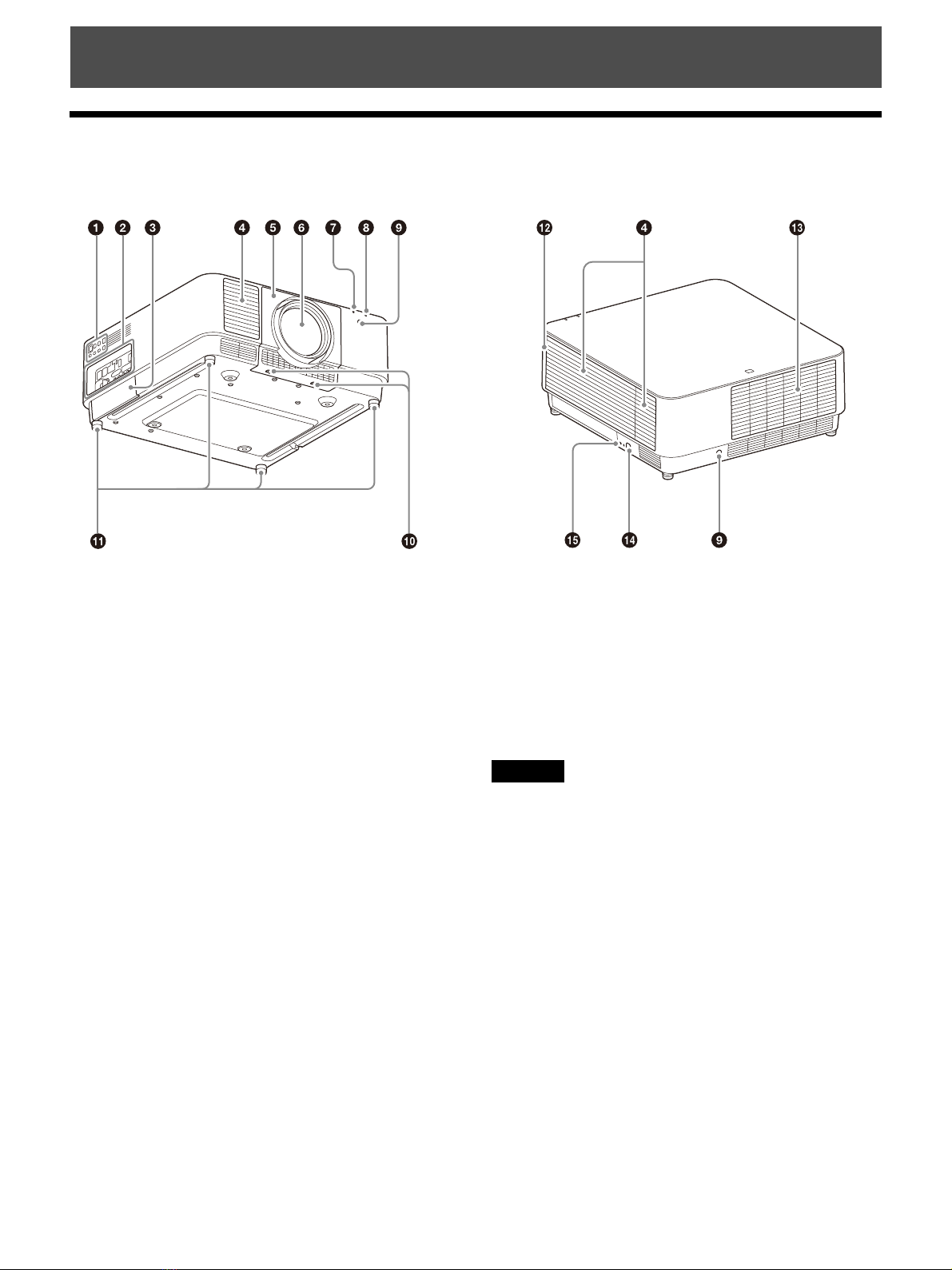
Location of Controls
Main Unit ........................................................... 4
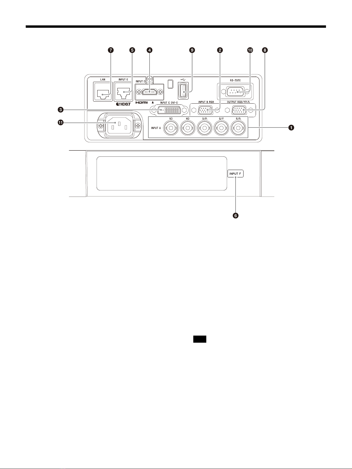
Terminals ........................................................... 5
Remote Commander and Control Panel ........... 6
Connections and Preparations
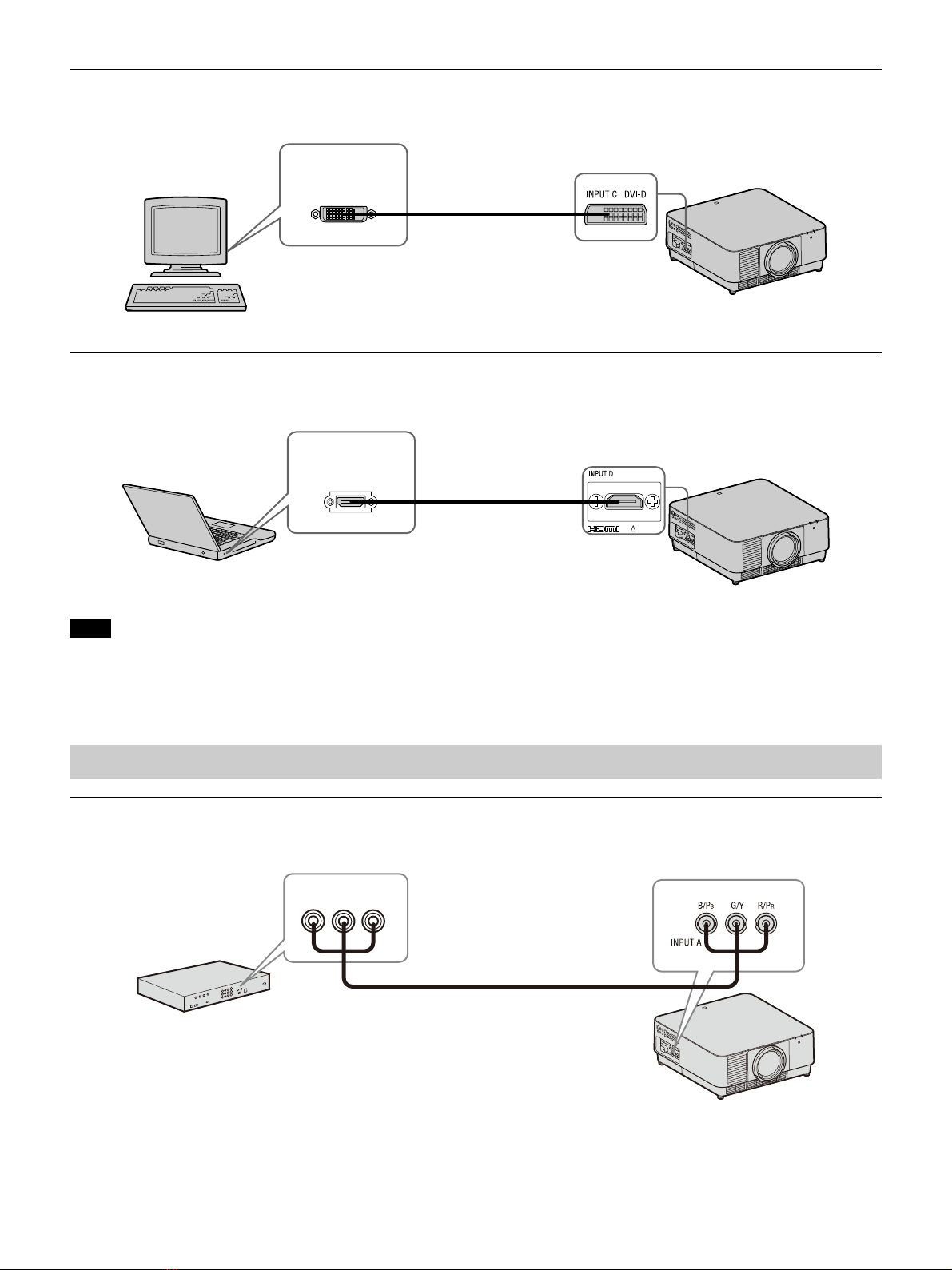
Connecting the Projector .................................. 8
Connecting to a Computer ........................... 8
Connecting to a Video Device ...................... 9
Connecting to an External Monitor .............10
Connecting to a Network Equipment ...........11
Connecting to a HDBaseT™ Device ..............11
Attaching the Projection Lens .......................... 13
Removing the Projection Lens .................... 13
Attaching the Terminal Cover ..........................14
Removing the Terminal Cover .....................14
Installing the Optional Adaptor ....................... 15
Projecting/Adjusting an Image
Projecting an Image .........................................16
Turning Off the Power .................................16
Adjusting the Projected Image ........................ 17
Focusing the image (Focus) ......................... 17
Adjusting the image size (Zoom) ................ 17
Adjusting the position of the image (Lens
shift) ........................................................... 17
Correcting for Trapezoidal Distortion of the
Projected Image (Keystone
Adjustment) ..............................................18
Correcting Image Twist (Warp Correction
Feature) .....................................................19
Blending Projections from Multiple Projectors
on a Screen ............................................... 20
Using Convenient Functions ............................ 21
Selecting the Stored Picture Settings (Picture
Position Function) (Specified Lens
Only) .......................................................... 21
Enlarging a Part of the Image (Digital Zoom
Function) ...................................................22
Projecting Images with Two Pictures
Simultaneously (Two-Picture Display
Function) ...................................................22
Adjustments and Settings Using a Menu
Using a Menu ....................................................23
Projection Setting Menu .................................. 24
The Screen Menu ..............................................27
The Function Menu .......................................... 29
The Operation Menu ....................................... 30
The Connection/Power Menu .......................... 31
The Installation Menu .......................................33
The Information Menu .................................... 36
Network Features
Using Network Features ...................................37
Displaying the Control Window of the
Projector with a Web Browser ..................37
Confirming the Settings for the
Projector ................................................... 38
Operating the Projector from a
Computer ................................................. 38
Using the e-mail Report Function .............. 38
Configure the Network Settings ................. 40
Setting the Control Protocol of the
Projector ....................................................41
About the HTML Viewer Function .............. 43
Using the Software Update Function ......... 45
Error Handling
Indicators ......................................................... 46
Messages List .................................................. 48
Troubleshooting .............................................. 49
Others
Cleaning the Air Filter ....................................... 51
Updating the Software .....................................52
Updating the Software via the USB
Memory .....................................................52
Updating the Software via the Network ......52