TABLE OF CONTENTS
Section Title
Page
Section Title
page
Service
Note
. . . . . . . . . . . . . . . . . . . . . . . . . . . . . . . . . . . . . . . . . . . . . . . . . . . . . . . . . . . . . . .
.3
6. ADJUSTMENTS
1.
2.
3.
4.
5.
GENERAL
. . . . . . . . . . . . . . . . . . . . . . . . . . . . . . . . . . . . . . . . . . . . . . . . . . . . . . . .
1-l
DISASSEMBLY
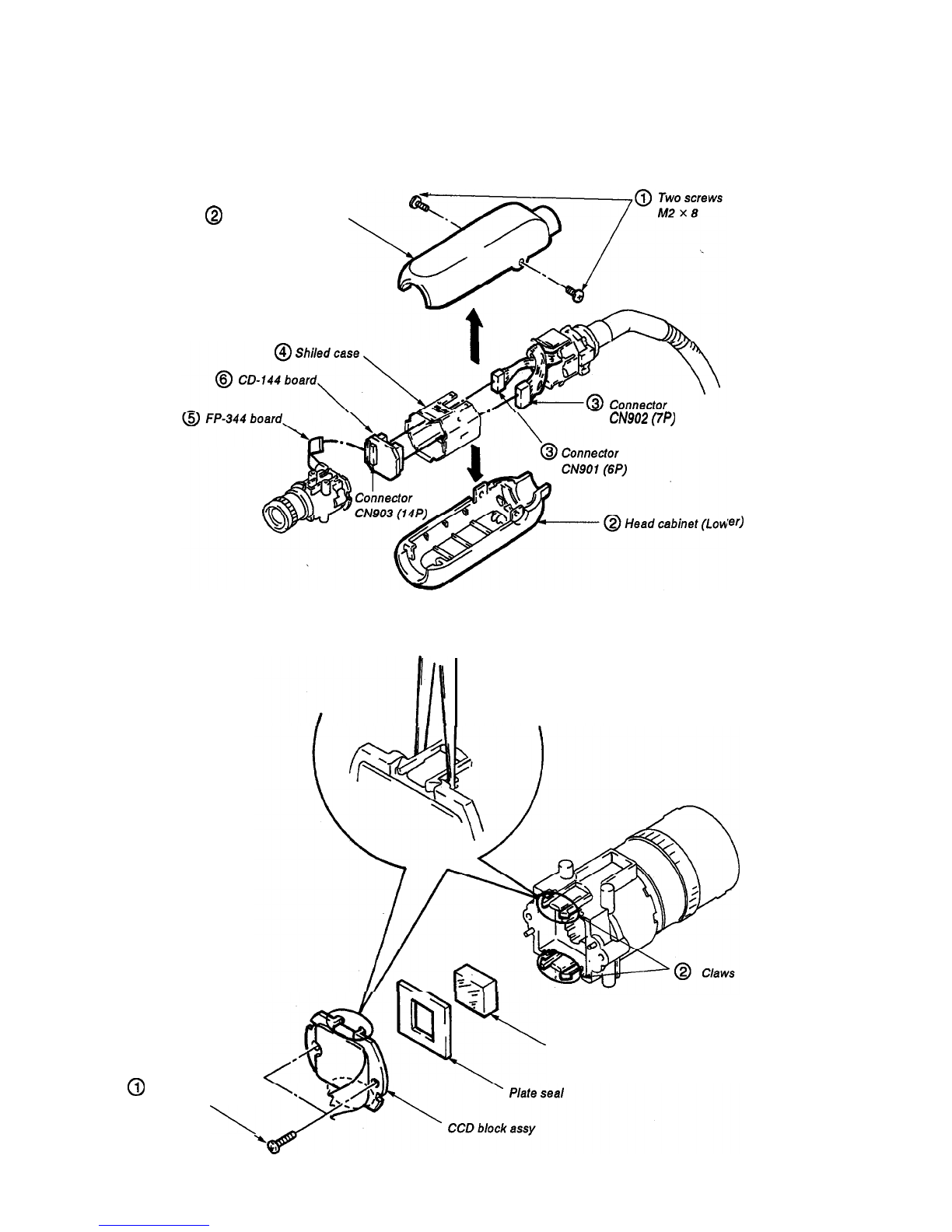
2-1. Removal of Head Cabinet (Upper, Lower) and
I
CD-144 Board
. . . . . . . . . . . . . . . . . . . . . . . . . . . . . . . . ..*...... . . . . . . .
2-l
2-2. Removal of Optical Filter Block and
CCD Block Assy
.
.
.
.
.
.
.
.
.
.
.
.
.
.
.
.
.
.
.
.
.
.
.
.
.
.
.
.
.
..#.............
2-l
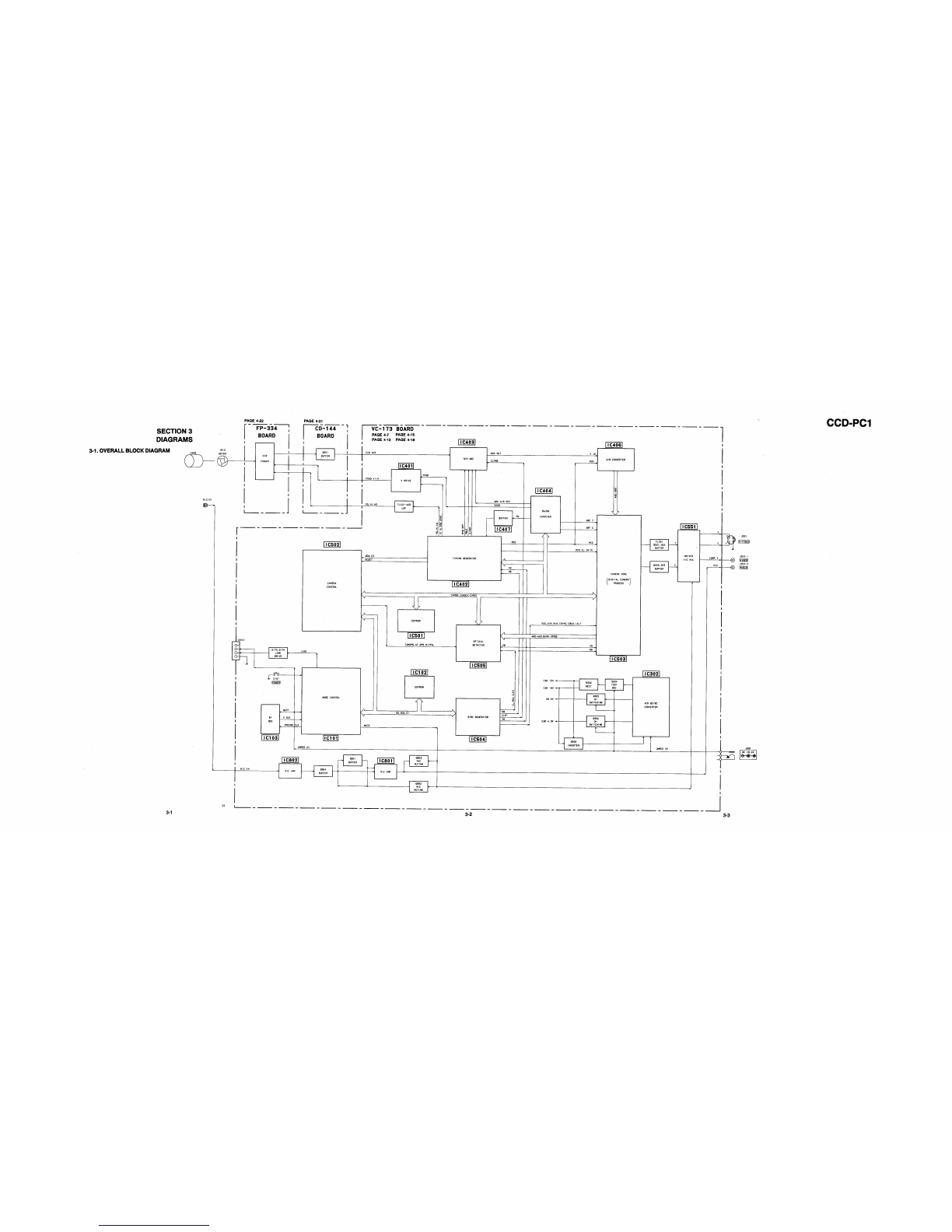
DIAGRAMS
3-1. Overall Block Diagram
. . . . . . . . . . . . . . . . . . . . . . . . . . . . . . . . . . ...3-1
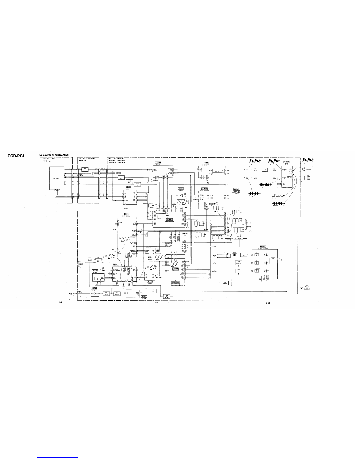
3-2. Camera Block Diagram
. . . . . . . . . . . . . . . . . . . . . . . . . . . . . . . . . . . . .
3-4
PRINTED WIRING BOARDS AND SCHEMATIC
DIAGRAMS
4-l. Frame Schematic Diagram
. . . . . . . . . . . . . . . . . . . . . . . . . . . . . . ...4-1
4-2. Printed Wiring Boards and Schematic Diagrams
*****.4-3
l
VC- 173 Board
. . . . . . . . . . . . . . . . . . . . . . . . . . . . . . . . . . . . . . . . . . . . . . . . .
4-4
. CD-144,
FP-334
Boar&
. . . . . . . . . . . . . . . . . . . . . . . . . . . . . . . . . . .
4-21
REPAIR PARTS LIST
S-
1. Exploded View
. . . . . . . . . . . . . . . . . . . . . . . . . . . . . . . . . . . . . . . . . . . . . . .
5-l
S-l-l. Head Cabinet Section
. . . . . . . . . . . . . . . . . . . . . . . . . . . . . . . . . .
5-1
5-2. Electrical Parts List
.
.
.
.
.
.
.
.
.
.
.
.
.
.
.
.
.
.
.
.
.
.
.
.
.
.
.
.
.
.
.
.
.
.
.
.
.
.
.
.
.
.
5-2
6-l. Camera Section Adjustment
............................. ..6-
1
l-l. Preparations Before Adjustment
(Camera Section)
.......................................
.6-l
l-1-1. List
of Se~iceToolsea..
...................
sneeaa&1
l-1-2.
Preparations
........................................
.6-z
l-l-3. p~cautions.. ....................................... .6-s
l-l-4.
Adjusting Remote Control
Unit.................6-
4
l-l-5.
PageFAddressList..
............................ .6-s
l-l-6. Data Processing................................... .6-7
1-2. Camera Syetem Adjustment .......................... .6-9
1-2-1.
l-2-2.
l-2-3.
l-2-4.
1-2-s.
l-2-6.
l-2-7.
l-2-8.
l-2-9.
Cautions when making adjustments
after changing major components
~~~~~~~~~*~~~~6-9
Power Supply Voltage Check
(VC-173 Board)
. . . . . . . . . . . . . . ..a................... 6-9
Oscillation Frequency Check
(VC-173 board)
. . . . . . . . . . . . . . . . . . . . . . . . . . . . . . . . . . . .
6-9
DpageData,C,ettingm
. . . . . . . .
a.....
. . . . . . . . . . .
mm.
6-10
Adjustments Setup
. . . . . . . . . . . . . . . . . . . . . . . . . . . . . .
6-10
Page F Data Initialization
......................
6-l 1
28 MHz Original Oscillation Adjustment
(VC-173
Board)
. . . . . . . . . . . . . , . . . . . . . . . . . . . . . . . . . .
6-12
V SUB Adjustment (VC-173 Board)
***...*e
6-13
PictureFrameSetting
. . . . . . .
meeeee
. . . . . . . . . . .
ea.
6-14
l-2-10. Entering Reference Data for the Auto White
Balance
Standard
Datp..
. . . . . . . . . . . . . . . . . . . . . . .
6s
15
l-2-11. Color Reproduction Adjustment......‘.‘..... 6-16
1-2-12. Auto White Balance Adjustment
*************
6-18
1-2-13. Check the Auto White Balance
****..******.**
6-19
1-3.
Arrangement Diagram for Adjustment Parts
*.***
6-20
SAFETY CHECK-OUT
After correcting the original service problem, perform the following
safety checks before releasing the set to the customer:
1.
Check the area of your repair for unsoldered or
4.
Look for parts which, though functioning, show
poorly-soldered connections. Check the entire obvious signs of deterioration. Point them out
board surface for solder splashes and bridges. to the customer and recommend their replace-
2.
Check the interboard wiring to ensure that no ment.
wires are “pinched” or contact high-wattage
5.
Check the
B+
voltage to see it is at the values
resistors. specified.
3.
Look for unauthorized replacement parts, par-
ticularly transistors, that were installed during a
previous repair. Point them out to the customer
and recommend their replacement.
SAFETY-RELATED COMPONENT WARNING!!
COMPONENTS IDENTIFIED BY MARK
A
OR DOTTED
LINE WITH MARK
8
ON THE SCHEMATIC DIAGRAMS
AND IN THE PARTS LIST ARE CRITICAL TO SAFE
OPERATION. REPLACE THESE COMPONENTS WITH
SONY PARTS WHOSE PART NUMBERS APPEAR AS
SHOWN IN THIS MANUAL OR IN SUPPLEMENTS PUB-
LISHED BY SONY.
-2-


 User manual")