Sony HT-MT300 User manual

SERVICE MANUAL
Sony Video & Sound Products Inc.
HT-MT300/MT301
SOUND BAR
SA-MT300/MT301
ACTIVE SPEAKER SYSTEM
9-896-353-01
2016L33-1
© 2016.12
US Model
Canadian Model
HT-MT300/SA-MT300
AEP Model
UK Model
HT-MT300/MT301/SA-MT300/MT301
Ver. 1.0 2016.12
HT-MT300/MT301
SA-MT300/MT301
• All of the units included in the HT-MT300 (SA-
MT300/SA-WMT300/Remote control) or HT-
MT301 (SA-MT301/SA-WMT301/Remote con-
trol) are required to confirming operation of
SA-MT300/MT301. Check in advance that you
have all of the units.
Note:
Be sure to keep your PC used for service and
checking of this unit always updated with the
latest version of your anti-virus software.
In case a virus affected unit was found during
service, contact your Service Headquarters.
Photo: SA-MT300
SPECIFICATIONS
COMPONENT MODEL NAME
HT-MT300 HT-MT301
Bar Speaker (Active Speaker System) SA-MT300 SA-MT301
Subwoofer (Active Subwoofer) SA-WMT300 SA-WMT301
Amplier section
US model:
POWER OUTPUT AND TOTAL HARMONIC
DISTORTION:
(FTC)
Front L + Front R:
With 4 ohms loads, both channels
driven, from 200 - 20,000 Hz; rated
15 W per channel minimum RMS
power, with no more than 1% total
harmonic distortion from 250 mW to
rated output.
POWER OUTPUT (reference)
Front L/Front R speaker blocks: 25 W
(per channel at 4 ohms, 1 kHz)
CND, AEP,UK models:
POWER OUTPUT (rated)
Front L + Front R: 20 W + 20 W
(at 4 ohms, 1 kHz, 1% THD)
POWER OUTPUT (reference)
Front L/Front R speaker blocks: 25 W
(per channel at 4 ohms, 1 kHz)
Inputs
USB
ANALOG IN
TV IN (OPTICAL)
USB section
(USB) port:
Type A (For connecting USB memory)
BLUETOOTH section
Communication system
BLUETOOTH Specification version 4.2
Output
BLUETOOTH Specification Power
Class 1
Maximum communication range
Line of sight approx. 25 m 1)
Frequency band
2.4 GHz band (2.4000 GHz -
2.4835 GHz)
Modulation method
FHSS (Freq Hopping Spread Spectrum)
Compatible BLUETOOTH profiles 2)
A2DP 1.2 (Advanced Audio Distribution
Profile)
AVRCP 1.6 (Audio Video Remote
Control Profile)
Supported Codecs 3)
SBC4)
Transmission range (A2DP)
20 Hz - 20,000 Hz (Sampling frequency
32 kHz, 44.1 kHz, 48 kHz)
1) The actual range will vary depending on
factors such as obstacles between
devices, magnetic fields around a
microwave oven, static electricity,
cordless phone use, reception
sensitivity, the operating system,
software applications, etc.
2) BLUETOOTH standard profiles indicate
the purpose of BLUETOOTH
communication between devices.
3) Codec: Audio signal compression and
conversion format
4) Abbreviation for Subband Codec
Front L/Front R speaker block section
Speaker system
Full range speaker system, Acoustic
suspension
Speaker
40 mm × 100 mm (1 5/8 in × 4 in) cone
type
General
Power requirements
DC 19.5 V (using the supplied AC
adapter connected to AC 100 V - 240 V,
50 Hz/60Hz power supply)
Power consumption
On: 25 W
Standby mode: 0.5 W or less
BLUETOOTH Standby mode is set to
on: 1.8 W or less*
BLUETOOTH Standby mode is set to
off: 0.5 W or less
*The system will automatically enter
Power saving mode when there is no
BLUETOOTH pairing history, even if
the BLUETOOTH standby mode is set
to on.
Dimensions* (approx.) (w/h/d)
500 mm × 54 mm × 103 mm
(19 3/4 in x 2 1/4 in x 4 1/8 in)
*Not including projection portion
Mass (approx.)
1.4 kg (3 lb 1 3/8 oz)
Compatible iPod/iPhone models
The compatible iPod/iPhone models are as
follows. Update your iPod/iPhone with the
latest software before using with the
system.
BLUETOOTH technology works with:
iPhone 7 Plus/iPhone 7/iPhone SE/iPhone
6s Plus/iPhone 6s/iPhone 6 Plus/
iPhone 6/iPhone 5s/iPhone 5c/iPhone 5
iPod touch (6th generation)/iPod touch
(5th generation)
Frequency band
2.4 GHz (2.4000 GHz - 2.4835 GHz)
Modulation method
FHSS (Freq Hopping Spread Spectrum)
Wireless transmitter section
• Bar Speaker (1)
• Subwoofer (1)
• R03 (size AAA) battery (2)
• Optical digital cable (1)
What’s in the Box
• Remote control (1)
Design and specifications are subject to
change without notice.
• AC adapter (1)
• AC power cord (mains lead) (1)
• Startup Guide
• Operating Instructions
• Speaker pad for the subwoofer (4)
• Please refer to service manual separately issued for Subwoofer.

HT-MT300/MT301
2
1. SERVICING NOTES ............................................. 3
2. DISASSEMBLY
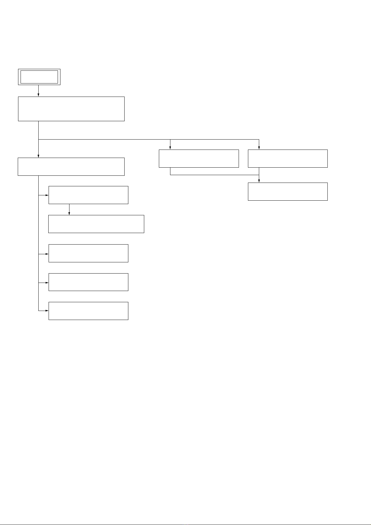
2-1. Disassembly Flow........................................................... 8
2-2. Top Cabinet Block, Bottom Cabinet Block .................... 9
2-3. Speaker Connection Cable.............................................. 10
2-4. Grille Frame Assy ........................................................... 11
2-5. Loudspeaker (L-ch, R-ch)............................................... 11
2-6. LED_CHUKEI Board..................................................... 12
2-7. TOUCH Board................................................................ 13
2-8. NFC Board...................................................................... 14
2-9. Bluetooth Module ........................................................... 15
2-10. JACK Board.................................................................... 16
2-11. MAIN Board ................................................................... 17
3. TEST MODE ............................................................ 18
4. TROUBLESHOOTING .......................................... 24
5. DIAGRAMS
5-1. Block Diagram - MAIN Section -................................... 27
5-2. Block Diagram
- PANEL/POWER SUPPLY Section -............................ 28
5-3. Printed Wiring Board - MAIN Board (Side A) - ............ 30
5-4. Printed Wiring Board - MAIN Board (Side B) - ............ 31
5-5. Printed Wiring Board - TOUCH Board - ........................ 32
5-6. Schematic Diagram - TOUCH Board -........................... 32
5-7. Printed Wiring Board - LED_CHUKEI Board -............. 33
5-8. Schematic Diagram - LED_CHUKEI Board - ............... 33
5-9. Printed Wiring Board - JACK Board -............................ 34
5-10. Schematic Diagram - JACK Board - .............................. 34
6. EXPLODED VIEWS
6-1. Foot Section .................................................................... 35
6-2. Top Cabinet Section........................................................ 36
6-3. Bottom Cabinet Section .................................................. 37
7. ELECTRICAL PARTS LIST .............................. 38
Accessories are given in the last of the electrical parts list.
TABLE OF CONTENTS
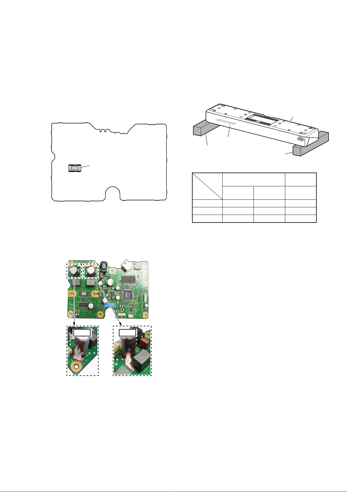
NOTES ON CHIP COMPONENT REPLACEMENT
• Never reuse a disconnected chip component.
• Notice that the minus side of a tantalum capacitor may be dam-
aged by heat.
This system incorporates Dolby* Digital.
* Manufactured under license from Dolby
Laboratories.
Dolby, Dolby Audio and the double-D
symbol are trademarks of Dolby
Laboratories.
The BLUETOOTH®word mark and logos are
registered trademarks owned by Bluetooth
SIG, Inc. and any use of such marks by Sony
Corporation is under license. Other
trademarks and trade names are those of
their respective owners.
The N Mark is a trademark or registered
trademark of NFC Forum, Inc. in the United
States and in other countries.
Android and Google Play are trademarks of
Google Inc.
Apple, the Apple logo, iPhone, iPod, iPod
touch, and Retina are trademarks of Apple
Inc., registered in the U.S. and other
countries. App Store is a service mark of
Apple Inc.
“Made for iPod,” and “Made for iPhone”
mean that an electronic accessory has
been designed to connect specifically to
iPod or iPhone, respectively, and has been
certified by the developer to meet Apple
performance standards. Apple is not
responsible for the operation of this device
or its compliance with safety and
regulatory standards. Please note that the
use of this accessory with iPod or iPhone
may affect wireless performance.
Copyrights and Trademarks “BRAVIA” logo is a trademark of Sony
Corporation.
“ClearAudio+” is a trademark of Sony
Corporation.
MPEG Layer-3 audio coding technology
and patents licensed from Fraunhofer IIS
and Thomson.
Windows Media is either a registered
trademark or trademark of Microsoft
Corporation in the United States and/or
other countries.
This product is protected by certain
intellectual property rights of Microsoft
Corporation. Use or distribution of such
technology outside of this product is
prohibited without a license from Microsoft
or an authorized Microsoft subsidiary.
All other trademarks are trademarks of
their respective owners.
SAFETY-RELATED COMPONENT WARNING!
COMPONENTS IDENTIFIED BY MARK 0OR DOTTED LINE
WITH MARK 0ON THE SCHEMATIC DIAGRAMS AND IN
THE PARTS LIST ARE CRITICAL TO SAFE OPERATION.
REPLACE THESE COMPONENTS WITH SONY PARTS
WHOSE PART NUMBERS APPEAR AS SHOWN IN THIS
MANUAL OR IN SUPPLEMENTS PUBLISHED BY SONY.
ATTENTION AU COMPOSANT AYANT RAPPORT
À LA SÉCURITÉ!
LES COMPOSANTS IDENTIFIÉS PAR UNE MARQUE 0SUR
LES DIAGRAMMES SCHÉMATIQUES ET LA LISTE DES
PIÈCES SONT CRITIQUES POUR LA SÉCURITÉ DE FONC-
TIONNEMENT. NE REMPLACER CES COMPOSANTS QUE
PAR DES PIÈCES SONY DONT LES NUMÉROS SONT DON-
NÉS DANS CE MANUEL OU DANS LES SUPPLÉMENTS
PUBLIÉS PAR SONY.

HT-MT300/MT301
3
SECTION 1
SERVICING NOTES
UNLEADED SOLDER
Boards requiring use of unleaded solder are printed with the lead-
free mark (LF) indicating the solder contains no lead.
(Caution: Some printed circuit boards may not come printed with
the lead free mark due to their particular size)
: LEAD FREE MARK
Unleaded solder has the following characteristics.
• Unleaded solder melts at a temperature about 40 °C higher
than ordinary solder.
Ordinary soldering irons can be used but the iron tip has to be
applied to the solder joint for a slightly longer time.
Soldering irons using a temperature regulator should be set to
about 350 °C.
Caution: The printed pattern (copper foil) may peel away if
the heated tip is applied for too long, so be careful!
• Strong viscosity
Unleaded solder is more viscous (sticky, less prone to flow)
than ordinary solder so use caution not to let solder bridges
occur such as on IC pins, etc.
• Usable with ordinary solder
It is best to use only unleaded solder but unleaded solder may
also be added to ordinary solder.
ADVANCE PREPARATION WHEN CONFIRMING OP-
ERATION
All of the units included in the HT-MT300 (SA-MT300/SA-
WMT300/Remote control) or HT-MT301 (SA-MT301/SA-WMT301/
Remote control) are required to confirming operation of SA-
MT300/MT301. Check in advance that you have all of the units.
NOTE OF PERFORMING THE OPERATION CHECK IN
THE STATE THAT HEAT SINK IS REMOVED
When performing the operation check in the state that this unit is
disassembled, it is possible to perform the operation check in the
state that heat sink is removed. However, don’t perform the opera-
tion check in the long time, and perform the operation check in the
volume state as low as possible.
ABOUT THE PROTECTION
All indicators on the main unit flash
for 10 seconds and the system is
turned off.
qThe protection feature is activated.
Disconnect the AC power cord (mains
lead) and check the items below.
– Make sure that the ventilations of
the main unit are not covered and
turn on the system after a while.
– When the system is using the USB
connection, remove the USB device
and turn on the system. If the
system operates properly, the
current of the connected USB device
is over the maximum output current
of the system 500 mA, or the USB
device may have an abnormality.
Æ
Æ
Æ
The SERVICING NOTES contains important information for servicing. Be sure to read this section before repairing the unit.
MODEL IDENTIFICATION
Distinguish by Part No. and Destination code of the model number
label on the bottom side of the main unit.
– Bottom view –
MODEL NUMBER LABEL
Destination code
Part No.
Model name
(color) Destination Part No. Destina-
tion code
SA-MT300
(Charcoal
Black)
US, CND 4-685-993-0[] (UC2)
AEP 4-685-994-0[] (CEL)
UK 4-691-844-0[] (CEK)
SA-MT300
(Crème White) US, CND 4-685-996-0[] (UC2)
SA-MT301
(Crème White)
AEP 4-685-997-0[] (CEL)
UK 4-691-852-0[] (CEK)
DESTINATION ABBREVIATIONS
The following abbreviations for model destinations are used in this
service manual.
• Abbreviations
AEP : European (Except for UK, Ireland), Eastern Europe area,
CIS area (Moldova) and Middle East area (Israel, Jordan)
models
CND : Canadian and Latin America (Puerto Rico) models
UK : UK and Ireland models

HT-MT300/MT301
4
NFC CONNECTION CHECKING METHOD
Be sure to perform the NFC connection check, according to the fol-
lowing procedure when having work of replaced following parts.
Replacing parts for repairing that required NFC connec-
tion check
• Replacing the MAIN board of bar speaker
• Replacing the NFC board of bar speaker
• Replacing the Bluetooth module of bar speaker
NFC connection checking method
After replacing the parts, it is necessary to update the BD address
information of the NFC board.
Be sure to perform the NFC connection check of bar speaker after
the resetting both of bar speaker and subwoofer, according to the
following procedure.
Procedure:
1. Connect the AC adapter to the bar speaker, and touch the two
buttons of [–] and [1] on the bar speaker at the same time for
about 5 seconds in the power on state.
front side
Right top surface of bar speaker
2. Hold down the [SECURE LINK] button on the subwoofer and
insert the AC power cord into the wall outlet.
Subwoofer
(
rear side
)
(rear panel)
3. Check that the LED of the subwoofer repeats flashing alter-
nately red and green, then release the [SECURE LINK] button
on the subwoofer.
Subwoofer (rear panel)
Green
flash
Release the
[SECURE LINK] button.
Red
flash
4. Wait for a while until the LED of the subwoofer turns off.
5. When the LED of subwoofer turns off, press the [1] button on
the subwoofer to turn the power on.
Light off
Subwoofer (rear panel)
Green
flash
Red
flash
6. The green LED of the subwoofer changes from flashing quick-
ly to flashing slowly, then switching from flashing to lights up
and completing the wireless connection.
Subwoofer (rear panel)
Green
flash
(quick)
Green
flash
(slow)
Green
lights up
– Continued on next page –

HT-MT300/MT301
5
7. Perform NFC connection with the following.
By holding an NFC-compatible mobile
device such as a smartphone or tablet
near the N mark on the main unit, the
system is turned on automatically, then
pairing and BLUETOOTH connection are
performed automatically.
1Turn on the NFC function of the
mobile device.
2Touch the N mark on the main unit
with the mobile device.
Keep touching until the mobile
device vibrates and message
appears on the mobile device.
Follow the on-screen instructions to
complete pairing of the main unit
and mobile device.
Connecting to a Mobile
Device by One-Touch
Function (NFC)
Compatible devices
Smartphones, tablets, and music players
with the NFC function built-in
(OS: Android™ 2.3.3 or later, excluding
Android 3.x)
BLUETOOTH
indicator
3Make sure that the BLUETOOTH
indicator lights in blue.
A connection between the system
and mobile device has been
established.
4Start audio playback with the
music app on the connected
mobile device.
Sound is output from the system.
5Adjust the volume.
• Adjust the volume by pressing Ç
+/– on the remote control.
• Adjust the subwoofer volume by
pressing SW Ç+/– on the remote
control (page 19).
To stop playback by One-touch
function
Touch the N mark on the main unit with
the mobile device again.
BLUETOOTH will be disconnected.
• Depending on your device, you may need
to perform the following items on your
mobile device in advance.
– Turn on the NFC function.
– Install the “NFC Easy Connect”
application from Google Play™ and
start the application. (The application
may not be available in some countries/
regions.) For details, refer to the
operating instructions of your device.
• If your mobile device is a type that goes
into standby mode in response to
magnetic force, it may not be able to be
connected by NFC. When the One-touch
function does not work, connect it by
using the BLUETOOTH function (page 20).
Notes
8. Please refer to “RESETTING THE SYSTEM” on page 6 and
delete the pairing information.
WIRELESS CONNECTION (LINK) WORK OF BAR SPEAK-
ER AND SUBWOOFER
When the following parts are replaced, the wireless connection
(LINK) of the bar speaker and subwoofer will be disconnected.
Before returning repaired products to the customer, follow the pro-
cedure below to LINK the bar speaker and subwoofer.
If only the bar speaker or subwoofer is brought in for repair, wire-
less connection (LINK) is not possible. Refer to “What to do if
only bar speaker or subwoofer are brought in for repair”.
Replacing parts for repairing that required wireless con-
nection (LINK)
• Replacing the MAIN board of bar speaker
• Replacing the Bluetooth module of bar speaker or subwoofer
Wireless connection (LINK) method
Be sure to perform the wireless connection (LINK) after the reset-
ting both of bar speaker and subwoofer.
Connection procedure:
1. Connect the AC adapter to the bar speaker, and touch the two
buttons of [–] and [1] on the bar speaker at the same time for
about 5 seconds in the power on state.
front side
Right top surface of bar speaker
2. Hold down the [SECURE LINK] button on the subwoofer and
insert the AC power cord into the wall outlet.
Subwoofer
(
rear side
)
(rear panel)
3. Check that the LED of the subwoofer repeats flashing alter-
nately red and green, then release the [SECURE LINK] button
on the subwoofer.
Subwoofer (rear panel)
Green
flash
Release the
[SECURE LINK] button.
Red
flash
– Continued on next page –
.
.

HT-MT300/MT301
6
4. Wait for a while until the LED of the subwoofer turns off.
5. When the LED of subwoofer turns off, press the [1] button on
the subwoofer to turn the power on.
Light off
Subwoofer (rear panel)
Green
flash
Red
flash
6. The green LED of the subwoofer changes from flashing quick-
ly to flashing slowly, then switching from flashing to lights up
and completing the wireless connection.
Subwoofer (rear panel)
Green
flash
(quick)
Green
flash
(slow)
Green
lights up
What to do if only bar speaker or subwoofer are brought
in for repair
If only the bar speaker or subwoofer is brought in for repair situa-
tion, and the above parts are replaced, by customer must wireless
connection (LINK) the bar speaker and subwoofer.
If only the bar speaker is brought in for repair and re-
paired (If customer have the subwoofer at hand)
• After replacing parts of the bar speaker, perform only step 1 of
the above “Wireless connection (LINK) method” and turn the
power off of the bar speaker (bar speaker is reset).
• Inform the customer when returning the bar speaker that the
customer must wireless connection (LINK) the bar speaker
and subwoofer, and inform the customer of the step 2 and later
of “Wireless connection (LINK) method” above.
Note: When customer perform the SECURE LINK, do not need inform
of the procedure of “Wireless connection (LINK) method”. Please
inform customer that the SECURE LINK method is written in the
operating instructions.
If only the subwoofer is brought in for repair and re-
paired (If customer have the bar speaker at hand)
• After replacing parts of the subwoofer, perform only step 2 to
4 of the above “Wireless connection (LINK) method” and turn
the power off of the subwoofer (bar subwoofer is reset).
• Inform the customer when returning the subwoofer that the
customer must wireless connection (LINK) the bar speaker
and subwoofer, and please confirm customer choice either au-
tomatic LINK method or SECURE LINK method.
• If customer choice automatic LINK, please explain to cus-
tomer that bar speaker setting is cleared, and please inform the
customer the following procedure.
Procedure:
1. Connect the AC adapter to the bar speaker, and touch the
two buttons of [–] and [1] on the bar speaker at the same
time for about 5 seconds in the power on state.
2. Press the [1] button on the subwoofer to turn the power
on.
3. The green LED of the subwoofer changes from flashing
quickly to flashing slowly.
4. The green LED of the subwoofer is switching from flash-
ing to lights up and complete the wireless connection
(LINK).
• When customer choice the SECURE LINK, not inform the
above automatic LINK procedure, and inform customer that
the SECURE LINK method is written in the operating instruc-
tions.
RESETTING THE SYSTEM
Æ
1Press and hold
Æ
and – on the
main unit for more than 5
seconds.
All indicators on the main unit flash
3 times, and the settings return to
their initial status.
2Disconnect the AC power cord
(mains lead).
3Connect the AC power cord (mains
lead), then press
Æ
to turn on the
system.
4Link the s
y
stem to the subwoofer
NOTE OF REPLACING THE NFC BOARD FOR RE-
PAIRING
When the NFC board is defective, replace the complete mounted
board.
The mounted parts cannot be replaced with single for repairing.
Also, after replacing the NFC board please refer to “NFC CON-
NECTION CHECKING METHOD” on page 4.
NOTE OF REPAIRING THE MAIN BOARD
Among mounted parts on the MAIN board, only parts that are de-
scribed in the electrical parts list can be replaced for repair.
When the parts that are not described in the electrical parts list are
defective, replace the complete mounted board.
In this service manual, the schematic diagram of the MAIN board
is not described.
Also, after replacing the MAIN board please refer to “NFC CON-
NECTION CHECKING METHOD” on page 4, “WIRELESS
CONNECTION (LINK) WORK OF BAR SPEAKER AND SUB-
WOOFER” on page 5 and “SPREADING OF COMPOUND” on
page 7.

HT-MT300/MT301
7
NOTE OF REPLACING THE ELECTRICAL PARTS ON
EACH BOARDS FOR REPAIRING
Among mounted electrical parts on each boards, only parts that
are described in the electrical parts list can be replaced for repair.
The parts that are not described in the electrical parts list cannot be
replaced with single for repairing.
SPREADING OF COMPOUND
When the IC1001 on the MAIN board or the MAIN board is re-
placed, spread the compound to the touching portion between the
IC1001 and the heat sink.
IC1001
– MAIN Board (Side A) –
compound
BOND FIXED POSITION OF ELECTRICAL PARTS
When the parts that fixed on the board by the bond have been re-
moved, fix the parts by using the bond (ADHESIVE (SC608Z2))
in the mounting to the board.
(Refer to the figure below)
[ ]: Bond application portion
C1040 C1038
– MAIN Board (Side A) –
MALFUNCTION PREVENTION OF THE BUTTON (TOUCH
PANEL SWITCH)
When the button portion on the top side of the main unit are
touched with something such as the floor surface, there is a pos-
sibility of occurring the malfunction.
When performing the operation check in the state that the top side
on this unit is under, set the stand etc. to the position that avoids the
button portion as shown in the figure below, perform in the state
that the button portion does not touch anything.
bottom side
stand
stand
button portion
COLOR VARIATION
HT-MT300
SA-MT300
HT-MT301
SA-MT301
Charcoal
Black
Crème
White
Crème
White
US, CND zz –
AEP z–z
UK z–z

HT-MT300/MT301
8
SECTION 2
DISASSEMBLY
• This set can be disassembled in the order shown below.
2-1. DISASSEMBLY FLOW
SET
2-2. TOP CABINET BLOCK,
BOTTOM CABINET BLOCK
(Page 9)
2-4. GRILLE FRAME ASSY
(Page 11)
2-3. SPEAKER CONNECTION CABLE
(Page 10)
2-6. LED_CHUKEI BOARD
(Page 12)
2-7. TOUCH BOARD
(Page 13)
2-8. NFC BOARD
(Page 14)
2-9. BLUETOOTH MODULE
(Page 15)
2-10. JACK BOARD
(Page 16)
2-11. MAIN BOARD
(Page 17)
2-5. LOUDSPEAKER (L-CH, R-CH)
(Page 11)
BOTTOM CABINET BLOCK
TOP CABINET BLOCK

HT-MT300/MT301
9
Note: Follow the disassembly procedure in the numerical order given.
2-2. TOP CABINET BLOCK, BOTTOM CABINET BLOCK
connector
(CN2006)
1eight screws
(BVTP3 u10)
1six screws
(BVTP3 u10)
3filament tape
(sub material)
front side
front side
top cabinet block
5Open the top cabinet
block in the direction
of the arrow.
left side
right side
left side
right side
2Lift up the top cabinet block
in the direction of the arrow
at about a 90-degree angle.
6speaker connection cable
connector (CN1001)
7top cabinet block
Note: Lay a soft piece of cloth under the unit
to avoid damaging the top cabinet.
top side
top side
top cabinet
4FFC 20P
(CN2006)
8bottom cabinet block
FFC 20P
front side
$IIL[LQJWKHILODPHQWWDSHVXEPDWHULDO
The opposite side
is terminal side.
MAIN board
filament tape
(sub material)
Two folding.

HT-MT300/MT301
10
2-3. SPEAKER CONNECTION CABLE
front side
Press.
cushion (CL3)
left side
right side
1 cushion
(CL3)
2 Draw the speaker
connection cable
out of eight grooves.
6SHDNHUFRQQHFWLRQFDEOHVHWWLQJ
three
grooves
3 terminal (narrow)
[black/red]
3 terminal (wide)
[red/red]
3 terminal (wide)
[gray/gray]
3 terminal (narrow)
[black/gray]
left side
4speaker
connection
cable
Note 1: Lay a soft piece of cloth under the unit
to avoid damaging the top cabinet.
three
grooves
two
grooves
Arrange the speaker connection cable
in the direction of the arrow. Arrange the speaker connection cable
in the direction of the arrow.
front side
loudspeaker (L-ch)
speaker connection
cable
terminal (wide)
[gray/gray]
terminal (narrow)
[black/gray]
[black][gray]
right side
front side
speaker connection cable loudspeaker (R-ch)
terminal (wide)
[red/red]
terminal (narrow)
[black/red]
front side
top side
3DVWLQJSRVLWLRQRI
WKHFXVKLRQ&/
front
side
,QVWDOODWLRQGLUHFWLRQIRUWKHWHUPLQDOV5FK
Note 2: When connecting the terminals of the speaker
connection cable to the loudspeaker, be careful
of the direction of the terminals.
,QVWDOODWLRQGLUHFWLRQIRUWKHWHUPLQDOV/FK
OK NGOK NG
OK NG
OK NG
top cabinet block
Note 2: When connecting the terminals of the speaker connection
cable to the loudspeaker, be careful of the direction of the
terminals.

HT-MT300/MT301
11
2-4. GRILLE FRAME ASSY
2-5. LOUDSPEAKER (L-CH, R-CH)
screw boss
front side
left side
right side
1two screws
(BVTP3 u10)
1two screws
(BVTP3 u10)
1two screws
(BVTP3 u10) top side
concave
screw boss
two screw
bosses
two screw
bosses
concave
concave
concave
concave
concave
Note 1: Lay a soft piece of cloth under the unit
to avoid damaging the top cabinet.
2grille frame assy
Note 2: When installing the grille frame assy, align
the six screw bosses and six concaves.
top cabinet block
Note 2: Do not touch this portion.
rear side
left side
right side
1two screws
(BVTP3 u8)
1two screws
(BVTP3 u8)
1two screws
(BVTP3 u8)
1two screws
(BVTP3 u8)
2 loudspeaker (R-ch)
Note 3: When installing the loudspeaker (R-ch),
check the position of the terminals and
install it in the correct orientation.
Note 2: Do not touch this portion.
Note 1: Lay a soft piece of cloth under the unit
to avoid damaging the top cabinet.
terminals
terminals
2 loudspeaker (L-ch)
Note 3: When installing the loudspeaker (L-ch),
check the position of the terminals and
install it in the correct orientation.
top side
top cabinet block

HT-MT300/MT301
12
2-6. LED_CHUKEI BOARD
4screw
(BVTP3 u8)
4screw
(BVTP3 u8)
7FFC 20P
(CN5001)
6filament tape
(sub material)
slot
1FFC 6P
(CN5003)
2TOUCH board cable
connector (CN5002)
3 Draw the TOUCH board cable
out of two grooves.
NFC board
FFC 6P
LED_CHUKEI
board
LED_CHUKEI board
The opposite side
is terminal side.
CN5001
long short
LED_CHUKEI board
CN5001
MAIN board
CN2006
TOUCH board
728&+ERDUGFDEOHVHWWLQJ
two grooves
TOUCH
board
cable
LED_CHUKEI board
5Draw the LED_CHUKEI board out
of the slot in top cabinet block.
filament tape
(sub material)
FFC 20P
front side
left side
right side
Note 1: Lay a soft piece of cloth
under the unit to avoid
damaging the top cabinet. top side
CN5002
rear side
+RZWRLQVWDOOWKHIOH[LEOHIODWFDEOH
$IIL[LQJWKHILODPHQWWDSHVXEPDWHULDO
hole
hole
hole
boss
boss
boss
8LED_CHUKEI board
Note 2: When installing the
LED_CHUKEI board,
align the three bosses
and three holes.
)OH[LEOHIODWFDEOHVHWWLQJ
CN5003
The opposite side
is terminal side.
rear side
: Mountain fold
: Valley fold
41 47 25 25 15 15 55 17
195
Unit: mm
top cabinet block

HT-MT300/MT301
13
2-7. TOUCH BOARD
boss
hole
hole
boss
rib
rib
5 adhesive
(VG1)
top cabinet
TOUCH board
6TOUCH board
Note 2: When installing the TOUCH board,
align the two bosses and two holes.
4Draw the TOUCH board
block out of the two ribs
in top cabinet block.
front side
left side
right side
Note 1: Lay a soft piece of cloth under the unit
to avoid damaging the top cabinet.
TOUCH board
728&+ERDUGFDEOHVHWWLQJ
two grooves
TOUCH
board
cable
LED_CHUKEI board CN4001
rear side
1 Draw the TOUCH board cable
out of two grooves.
top side
2TOUCH board cable
connector (CN4001)
flathead screwdriver, etc.
3Gradually peel off the TOUCH board with
a flathead screwdriver, etc.
Note 3: The TOUCH board is affixed to the top cabinet
with a strong adhesive sheet.
When removing the TOUCH board, take care
so that you do not damage it.
top cabinet block
guide line
(starting point)
adhesive (VG1)
TOUCH board
3DVWLQJSRVLWLRQRIWKHDGKHVLYH9*

HT-MT300/MT301
14
2-8. NFC BOARD
5NFC board
3Draw the NFC board
block out of the rib in
top cabinet block.
rib
4 double
adhesive
tape
1FFC 6P
(CN001)
top cabinet
NFC board
front side
left side
right side
NFC board
FFC 6P
LED_CHUKEI board
)OH[LEOHIODWFDEOHVHWWLQJ
CN001
short
The opposite side
is terminal side.
rear side
flathead screwdriver, etc.
top side
Note 2: Lay a soft piece of cloth under the unit
to avoid damaging the top cabinet.
2Gradually peel off the NFC board with
a flathead screwdriver, etc.
Note 3: The NFC board is affixed to the top
cabinet with a strong adhesive sheet.
When removing the NFC board, take
care so that you do not damage it.
top cabinet block
long
Note 1: When the NFC board is replaced, refer to “NFC CONNEC-
TION CHECKING METHOD” on page 4.

HT-MT300/MT301
15
2-9. BLUETOOTH MODULE
1FFC 18P
(CN2002)
7FFC 18P
(CN2002)
6filament tape
(sub material)
2screw
(BVTP3 u10)
2screw
(BVTP3 u10)
8BT cushion
9bluetooth
module
5BT holder
BT cushion
hole
boss
rib BT holder
bluetooth module
filament tape
(sub material)
bluetooth
module
bluetooth module
FFC 18P
MAIN
board
CN2002
FFC 18P
4screw
(BVTP3 u8)
front side
rear side
left side
right side
)OH[LEOHIODWFDEOHVHWWLQJ
The opposite side
is terminal side.
front
side
3Remove the bluetooth
module block in the
direction of the arrow.
terminal
side
3DVWLQJSRVLWLRQRI
WKHILODPHQWWDSH
VXEPDWHULDO
+RZWRLQVWDOOWKHEOXHWRRWKPRGXOH
hole
Attach in order from 1to 4.
1Pass the FFC through the hole
of the BT holder.
2Align the cushion (BT)
and the rib.
3Align the hole
and the boss.
4Push in the bluetooth
module to lock it.
bottom cabinet block
Note: When the bluetooth module is replaced, refer to “NFC CON-
NECTION CHECKING METHOD” on page 4 and “WIRE-
LESS CONNECTION (LINK) WORK OF BAR SPEAKER
AND SUBWOOFER” on page 5.

HT-MT300/MT301
16
2-10. JACK BOARD
5Draw the jack and connector
out of the two holes in bottom
cabinet block.
1Remove the JACK board cable
from the wiring stopper.
2JACK board cable
connector (CN6001)
3JACK board cable
connector (CN6003)
4two screws
(BVTP3 u8)
hole
hole
Install the JACK board while pressing
the JACK board cable toward the MAIN
board side.
MAIN board
front side
rear side
left side
right side
:LUHVHWWLQJ
wiring stopper JACK board
MAIN board CN6001
rear side
hole
hole
rib
rib
6JACK board
Note: When installing the JACK board,
align the two ribs and two holes.
1RWHDERXWLQVWDOOLQJWKH-$&.ERDUG
front side
JACK board cable
bottom cabinet block

HT-MT300/MT301
17
2-11. MAIN BOARD
0Draw the jack and connector
out of the two holes in bottom
cabinet block.
bottom cabinet block
5two screws
(BVTP3 u8)
7screw
(BVTP3 u8)
7screw
(BVTP3 u8)
7screw
(BVTP3 u8)
3screw
(BVTP3 u8)
3screw
(BVTP3 u8)
7screw
(BVTP3 u8)
7screw
(BVTP3 u8)
8wiring stopper
front side
rear side
left side
right side
boss
rib
rib
boss
rib
rib
hole
hole
qa MAIN board
Note 4: When installing the MAIN board,
align the two ribs and two holes.
6heat sink
Note 3: When installing the heat
sink, align the two bosses
and two holes.
4analog bracket
Note 2: When installing the analog
bracket, align the rib and hole.
4analog bracket
Note 2: When installing the analog bracket,
align the rib and hole.
1JACK board cable
connector (CN3000)
2JACK board cable
connector (CN3401)
9
hole
hole
hole
hole
Note 1: When the MAIN board is replaced, refer to “NFC CONNEC-
TION CHECKING METHOD” on page 4, “WIRELESS
CONNECTION (LINK) WORK OF BAR SPEAKER AND
SUBWOOFER” on page 5 and “SPREADING OF COM-
POUND” on page 7.

HT-MT300/MT301
18
SECTION 3
TEST MODE
Button and LED position:
front side
Button position
LED position
RESET
It can return the main unit to setting to the initial state.
Procedure:
1. Touch the [1] button to turn the power on.
2. Touch the two buttons of the [–] and [1] at the same time for
about 5 seconds.
3. The all LEDs are flash 3 times.
Flash 3 times
4. The reset is completed, then main unit is restart.
DEMO MODE
The demo mode can be performed.
There are two methods of main unit operation and remote control
operation.
Note 1: It can not be operated with the remote control included with this
main unit.
Please use the following remote control.
Example:
REMOTE COMMANDER RMT-AH240U
(Part No.: 1-493-142-11)
REMOTE COMMANDER RMT-AH240E
(Part No.: 1-493-143-11)
In addition to the above remote control, it is possible to operate
if the remote control has the [RETURN] or [BACK] button, [IN-
PUT] ([INPUT +]) button, [MUTING] ([%]) button.
Procedure:
1. Touch the [1] button to turn the power on.
2. Perform a mode in operation with either the main unit or re-
mote control.
For the main unit operation:
Touch the two buttons of the [ ] and [–] at the same time for
about 5 seconds.
For the remote control operation:
Press the buttons on the remote control in the following order.
[RETURN] (or [BACK]) [ENTER] [INPUT] [MUT-
ING] [INPUT] [MUTING]
3. The LEDs light up/flash as shown in the following figure.
Light up in order from the left side
Flash 3 times
4. Enter the demo mode, then changed to the following setting for
demo mode and return to the normal display (function LED is
light up).
• Function : TV
• Volume : 31
• Sound field : CLEAR AUDIO+
• Subwoofer volume : 8
• Muting : OFF
• Night mode : OFF
• Voice : OFF
• Dual Mono : MAIN
Note 2: When demo mode is performed, the operation of the [1] button
on the main unit and remote control is invalid. Also, when insert
the AC power cord into the wall outlet in the demo mode state, the
power is automatically turned on and the demo mode is entered.
Releasing method:
Perform the “RESET” to release the demo mode.
Note 3: The demo mode does not release by unplug the AC power cord.
USB UPDATE MODE
This mode is guided by technical news, when update occurs.

HT-MT300/MT301
19
PANEL TEST
It can check the key input, model, destination, software version,
LED light up and subwoofer software.
Setting procedure:
1. Touch the [1] button to turn the power on.
2. Press the buttons on the remote control in the following order.
[u] [ANALOG] [– ] →[ +]
3. The LEDs light up as shown in the following figure.
Light up in order from the left side
Light off
Light up
4. The panel test mode is entered. Refer to the each following
items (“Key input check”, “Model/destination/software ver-
sion check”, “LED light up check” and “Subwoofer software
check”) and performing.
Releasing procedure:
1. Touch the [1] button, then the LEDs light off in the following
order.
“MOVIE” “ANALOG” “USB” “BLUETOOTH”
“TV” light off.
2. The panel test mode is released, then return to the normal dis-
play (function LED is light up).
3. Touch the [1] button again to the reset is performed, the all
LEDs are flash 3 times.
4. The reset is completed, then main unit is restart.
Key input check:
1. Press the [TV] button on the remote control.
2. The key input check mode is entered, then the LEDs light up/
flash as shown in the following figure.
Flash 3 times Light up
Light up
3. Each time a button on the main unit is touched, LED is light off
one by one from the right side.
However, once a button is touched, it is no longer taken into
count.
Light off one by one from the right side
4. When all the buttons are touched and the check is completed,
the LEDs of “TV”, “BLUETOOTH”, “USB”, “ANALOG”
and “MOVIE” continue flashing.
Continue flashing
5. Perform other panel test items or release the panel test mode.
Model/destination/software version check:
1. Press the [2+] button on the remote control.
2. The model/destination/software version check mode is en-
tered, then the LEDs light up/flash as shown in the following
figure.
Light up
Flash 3 times
Light up
Continue flashing Light up
Model disiplay
3. Each time the [2+] button on the remote control is pressed,
the LED display changes from “Destination” “MTK ver-
sion” “BT main S/W version” “BT main H/W version”
“BT woofer S/W version” “BT woofer H/W version”
“System version” in this order, and returns to the “Model”
display.
Display example
Destination:
Desti-
nation
LED
TV BLUE-
TOOTH USB ANA-
LOG
MOV-
IE
MU-
SIC
US,
CND ●○
AEP,
UK ●○
no mark: light off, ○: light up, ●: flashing
– Continued on next page –

HT-MT300/MT301
20
Software version (Except system version):
Soft-
ware
item
LED
TV BLUE-
TOOTH USB ANA-
LOG
MOV-
IE
MU-
SIC
MTK ○○ AB C
BT
main
S/W
○AB C
BT
main
H/W
○AB C ○
BT
woofer
S/W
○AB C
BT
woofer
H/W
○AB C ○
no mark: light off, ○: light up,
A: Major version, B: Minor (upper) version,
C: Minor (lower) version,
Example for the flashing of major version (A) and minor ver-
sion (B, C):
If the software version is “1.02”, repeat flashing in the follow-
ing order.
“USB” LED flash once “ANALOG” LED light off (skip)
“MOVIE” LED flash twice “USB” LED flash once ...
Software version (System version):
Soft-
ware
item
LED
TV BLUE-
TOOTH USB ANA-
LOG
MOV-
IE
MU-
SIC
System A B C D
no mark: light off,
A: Major version, B: Minor (upper) version,
C: Minor (middle) version, D: Minor (lower) version,
Example for the flashing of major version (A) and minor ver-
sion (B, C, D):
If the software version is “1.023”, repeat flashing in the follow-
ing order.
“BLUETOOTH” LED flash once “USB” LED light off
(skip) “ANALOG” LED flash twice “MOVIE” LED
flash 3 times “BLUETOOTH” LED flash once ...
4. Perform other panel test items or release the panel test mode.
LED light up check:
1. Press the [2–] button on the remote control.
2. The LED light up check mode is entered, then the LEDs light
up/flash as shown in the following figure.
Flash 3 times
Light upLight up
Light up
Pattern 1
Pattern 2
Light up
3. Perform other panel test items or release the panel test mode.
Subwoofer software check:
1. Press the [%] button on the remote control.
2. The subwoofer software check mode is entered, then check
result is displayed.
Light off
Check result: NG
Check result: OK
Continue flashing
3. After about 3 seconds, return to the normal display (function
LED is light up).
4. Perform other panel test items or release the panel test mode.
Other manuals for HT-MT300
3
This manual suits for next models
2
Table of contents
Other Sony Speakers System manuals

Sony
Sony HT-A5000 User guide

Sony
Sony SA-VA29 User manual

Sony
Sony SS-DP1000DW User manual

Sony
Sony SRS-RF90R User manual

Sony
Sony SRS-D511 User manual

Sony
Sony SS-K70ED Marketing User manual

Sony
Sony SA-FT1H User manual

Sony
Sony SS-V230 User manual

Sony
Sony SS-LAC305ED Installation instructions manual

Sony
Sony SRS-ZX1 User manual