Lencore GOLD A1U User manual

GOLD™
DESIGN, INSTALLATION AND
OPERATION GUIDELINES
(Model A1U)

table of contents
INTRODUCTION
Diagram
Wiring
Connections
Configuring the System
Flow Diagram
System Zoning
Speaker Layout
Installation
IR Wall Controls
Tuning and Balancing
Changing the IP Address
Operating the System from the Front Panel
1
2
4
4
6
7
8
9
12
20
23
33
34

RISK OF ELECTRIC SHOCK- DO NOT OPEN THE UNIT.
THERE ARE NO SERVICABLE COMPONENTS INSIDE.
IMPORTANT SAFETY INSTRUCTIONS
1) Read these instructions.
2) Keep these instructions.
3) Heed all warnings.
4) Follow all instructions.
5) Do not use this apparatus near water.
6) Clean only with dry cloth.
7) Do not block any ventilation openings. Install in accordance with the manufacturer's
instructions.
8) Do not install near any heat sources such as radiators, heat registers, stoves, or other
apparatus (including amplifiers) that produce heat.
9) Do not defeat the safety purpose of the polarized or grounding-type plug. A polarized plug
has two blades with one wider than the other. A grounding type plug has two blades and a
third grounding prong. The wide blade or the third prong are provided for your safety. If the
provided plug does not fit into your outlet, consult an electrician for replacement of the
obsolete outlet.
10) Protect the power cord from being walked on or pinched particularly at plugs, convenience
receptacles, and the point where they exit from the apparatus.
11) Only use attachments/accessories specified by the manufacturer.
12) Use only with the cart, stand, tripod, bracket, or table specified by the manufacturer, or sold
with the apparatus. When a cart is used, use caution when moving the cart/apparatus
combination to avoid injury from tip-over.
13) Refer all servicing to qualified service personnel. Servicing is required when the apparatus
has been damaged in any way, such as power-supply cord or plug is damaged, liquid has
been spilled or objects have fallen into the apparatus, the apparatus has been exposed to
rain or moisture, does not operate normally, or has been dropped.
WARNING To reduce the risk of fire or electric shock, do not expose this apparatus to rain
or moisture and do not expose to dripping or splashing and no objects filled with liquids,
such as vases, shall be placed on the apparatus
14)

Lencore Gold™ Sound Masking System Planning and Layout Guideline
Lencore provides layout and wiring diagrams at no cost – we encourage you to contact us
516-682-9292.
The following pages include design, installation and operation guidelines utilized to reach the best possible
performance from the Lencore sound masking system. The goal of a sound masking system is to provide
speech privacy by raising the ambient background noise with a comfortable sound that is uniform throughout
the space.
The Gold All-Inclusive Unit also provides for one music input source - such as an iPod, or other device (not
included), through an RCA jack. Music can be zoned separately from the sound masking.
Gold
Lencore’s Gold unit is an out of the box, stand-alone system incorporating amplifiers, equalizers, zone
modification and total control in one unit. The Gold unit is a 1RU rack mount unit that offers two Operating
Platforms (OPs) and a head-end in one unit. The system maintains the easy to use full one third octave
band equalizer that can be adjusted to either individual zones or all zones and provides exceptional fine-
tuning capabilities. Groupings of sound sources and channels let you customize an almost limitless number
of zones (up to 255) for masking and music, while maintaining the advantages of complete networked
operation and control.
The creation, modification, addition and deletion of zones for sound masking and music can be easily
controlled using the included Lencore System Manager or through the on-board buttons. No proprietary
software needs to be installed on the client’s side, eliminating security and migration issues. The Lencore
Gold unit is an open platform system. In addition, volume and equalizer settings for sound masking and
music can be programmed through System Manager offering tremendous adjustment and control
capabilities with unprecedented flexibility.
1
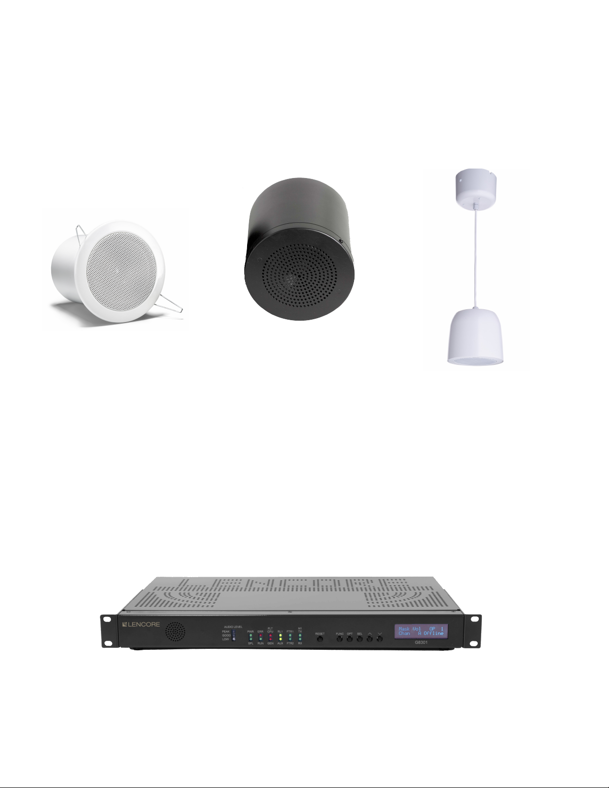
Sound Masking Speakers
The Gold system utilizes either 4" direct-fired or 6" in-plenum speakers. Direct-fired speakers are either mounted in the
ceiling (Gold Direct Fired Tangent) or attached to the ceiling / deck (Gold Decorative Pendant) and face downward for
direct, unimpeded delivery of the sound. Gold in-plenum speakers are mounted above the ceiling, in the plenum space
between the ceiling and the deck above; they fill the plenum with sound which then filters down through the ceiling into
the space below. Because of the difference in the way that the sound is dispersed there are different design and layout
guidelines based on which speaker system is being used. All speakers are powered through the headend device via Cat5e
RJ45 cables.
Headend
The Gold 1 RU rack mounted or stand-alone (rubber feet included in box) headend contains all of the controls and
processors for generating the sound masking. It also has one RCA audio input for adding background music which is
controlled independently of the sound masking. This headend control is simple to install and easy to maintain either directly
on the unit itself or through the graphic user interface named System Manager.
Gold Direct Fired Tangent Gold In-Plenum Universal
Gold Decorative Pendant
2
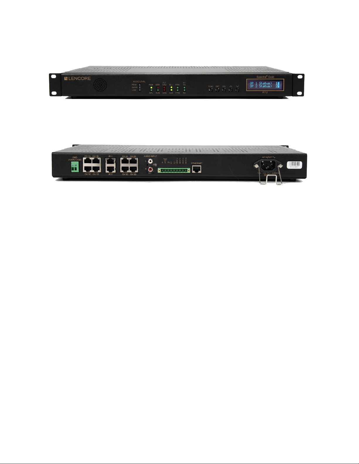
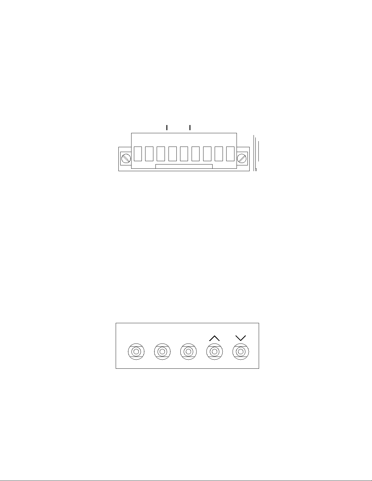
Rear Panel
1. Audio Level LEDs
The Audio Level LEDs indicate the audio
input level as low, good, or clipped.
2. LED Indicators
The LED indicators display various
conditions and functions such as network
activity and relay status. See “Using the
System” for detailed information.
3. Buttons
The switches are used to make a number of
adjustments to the system without using a
computer.
4. LCD display
The LCD displays various diagnostic
messages and configuration information
about the system.
5. GND
For external auxiliary equipment.
6. OP1 speaker connectors
Speaker connectors for OP1 channels A, B,
C, and D using RJ45 connectors.
7. IR Inputs
Connect the IR input to a Lencore’s IR
device using an RJ45 cable for OP1 and OP2.
8. OP2 speaker connectors
Speaker connectors for OP2 channels A, B,
C, and D using RJ45 connectors.
9. RCA Audio Input
Connect a line level audio source using an
RCA cable.
10. AUX connector
Connector for external equipment.
11. Ethernet
Connect an Ethernet cable to access the
Protocessor.
12. Power Input
Power cord connector (IEC 60320).
100-240VAC.
Front Panel
12 3 4
5678910 11 12
3
Wiring
Power and Network connections:
1. Plug the unit into a standard 115VAC power outlet. The system will be usable in approximately
two minutes. The AUX LED will flash while the system is booting-up and be solid when the
system is ready.
2. Connect a network cable to the unit’s Ethernet input to access the Protocessor. The Protocessor
is the network server. The Protocessor is pre-loaded with Lencore’s System Manager. System
Manager allows adjustment to the system’s characteristics.
Note: The network cable must be a standard Ethernet cable not power over Ethernet (POE).
Ground connection:
1. For future use in expandable interface solutions.
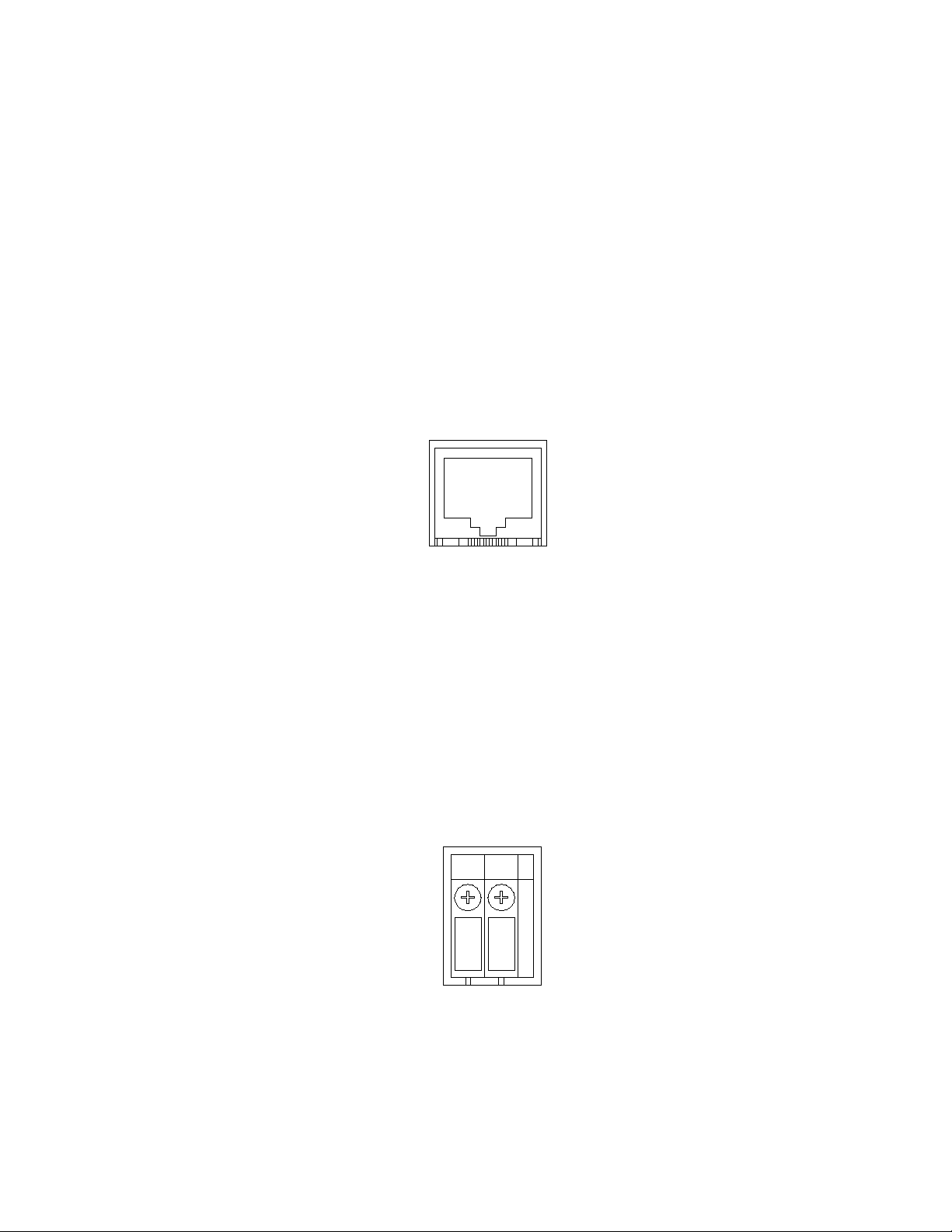
ETHERNET
GND
(AUDIO COM)
4
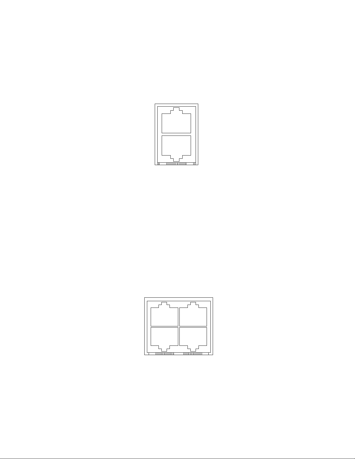
IR connections:
1. Connect an IR unit to the IR port.
IR1 for OP1 speakers.
IR2 for OP2 speakers.
Speaker connections:
1. Connect the external speakers to the appropriate channel using cat 5 RJ45 cables.
IR 1
IR 2
CH 1A CH 1B
CH 1C CH 1D
5
Auxiliary Connection
Connect an external device’s fault input to Aux “Fault Out” Relay R1 - NC and C. Relay R1 is energized
(closed) when no fault exists and de-energized (open) when a fault is active.
Input 1A and 1B are for future use.
Input 2A and 2B are for future use.
Configuring the System
The system must be configured before the music function is used. The switches can be used to
configure and adjust the system for many functions. System Manager must be used to create any
zones or to make more detailed adjustments such as equalizer settings. See below for switches usage
and System Manager operations.
Front Panel Switches:
The switches allow the user to make a number of adjustments to the system without using a computer,
although, a computer and System Manager are still required for full control of all functions. A selection
can be made by continually pressing and releasing the switch.
NC
C
NO
N.C.
R1
N.C.
INPUT 1 A
INPUT 1 B
INPUT 2 A
INPUT 2 B
OUT
FAULT
FUNC OPT SEL
6
Flow Diagram
Cabling Types and Distances
The advantage to Gold sound masking over other systems is the use of UTP four pair / category type cabling with EIA/TIA
568B standard termination. Recommended CMP type cabling (plenum rated cable), is NOT supplied as part of the
system. Contact your local supplier for cable.
Home run cabling (typically supplied and cut to length in the field by the installer) is a “Signal Cable” found between the
Gold headend OP Channel and the first speaker on that channel. There are eight (8) channels on the Gold headend and
up to eight (8) speakers per channel (for a total of 64 speakers).
Interconnect cables are utilized by both types of speakers. Connect the Output jack of a previous speaker to the Input
jack of the next speaker in a daisy chain fashion.
Cable Cabling Type Speaker
Signal Cable
West Penn 254245
Belden 1501A or Equivalent
Category 5, 5e, 6 / 4-Pair (8
Conductor) 24 AWG Solid CMP
300 ft from headend to last
speaker
Back View
*Diagram above is for wiring purposes only and is not an exact representation of the actual unit
Gold utilizes both direct fired (Gold Direct Fired Tangent and Gold Decorative Pendant) and indirect firing (Gold Universal In-Plenum) speakers.
Based on the space and the layout, each channel can accommodate up to 8 speakers per channel. Speakers on each channel are daisy-chained
together.
1 to 8 Speakers per Channel
7
Table of contents
Other Lencore Speakers System manuals


