manuals.online logo
Brands
  1. Home
  2. •
  3. Brands
  4. •
  5. Sony
  6. •
  7. Stereo Receiver
  8. •
  9. Sony XAV-9500ES User manual

Sony XAV-9500ES User manual

XAV-9500ES
5-021-903-25(1)
XAV-9500ES(IN)
https://rd1.sony.net/help/ev/xav-95/h_zz/
AV RECEIVER Operating Instructions GB
To cancel the demonstration (Demo Mode) display, see
page 7.
To switch the FM/AM tuning step, see page 7.
2GB
Warning
The nameplate indicating operating voltage, etc., is
located on the bottom of the chassis.
The validity of the CE marking is restricted to only
those countries where it is legally enforced, mainly
in the countries EEA (European Economic Area) and
Switzerland. The validity of the UKCA marking is
restricted to only those countries where it is legally
enforced, mainly in the UK.
WARNING
To prevent fire or shock hazard, do not
expose the unit to rain or moisture.
To avoid electrical shock, do not open the
cabinet. Refer servicing to qualified personnel
only.
Disposal of waste batteries and
electrical and electronic
equipment (applicable in the
European Union and other
countries with separate collection
systems)
WARNING: Do not ingest battery,
Chemical Burn Hazard.
The remote commander contains a coin/
button cell battery. If the coin/button cell battery is
swallowed, it can cause severe internal burns in just
2 hours and can lead to death.
Keep new and used batteries away from children. If
the battery compartment does not close securely,
stop using the product and keep it away from
children.
If you think batteries might have been swallowed or
placed inside any part of the body, seek immediate
medical attention.
Note on the lithium battery
Do not expose the battery to excessive heat such as
direct sunlight, fire or the like.
Disclaimer regarding services offered by third
parties
Services offered by third parties may be changed,
suspended, or terminated without prior notice.
Sony does not bear any responsibility in these sorts
of situations.
For safety, be sure to install this unit in the
dashboard of the car as the rear side of the unit
becomes hot during use.
For details, see “Connection/Installation”
(page 12).
Warning if your car’s ignition has no ACC
position
Do not install this unit in a car that has no ACC
position. The display of the unit does not turn off
even after turning the ignition off, and this
causes battery drain.
3GB
Caution
IN NO EVENT SHALL SONY BE LIABLE FOR ANY
INCIDENTAL, INDIRECT OR CONSEQUENTIAL
DAMAGES OR OTHER DAMAGES INCLUDING,
WITHOUT LIMITATION, LOSS OF PROFITS, LOSS OF
REVENUE, LOSS OF DATA, LOSS OF USE OF THE
PRODUCT OR ANY ASSOCIATED EQUIPMENT,
DOWNTIME, AND PURCHASER’S TIME RELATED TO
OR ARISING OUT OF THE USE OF THIS PRODUCT, ITS
HARDWARE AND/OR ITS SOFTWARE.
Dear customer, this product includes a radio
transmitter.
Please check your vehicle operation manual or
contact the manufacturer of your vehicle or your
vehicle dealer, before you install this product into
your vehicle.
Emergency calls
This BLUETOOTH car handsfree and the electronic
device connected to the handsfree operate using
radio signals, cellular, and landline networks as well
as user-programmed function, which cannot
guarantee connection under all conditions.
Therefore do not rely solely upon any electronic
device for essential communications (such as
medical emergencies).
On BLUETOOTH communication
• Microwaves emitting from a BLUETOOTH device
may affect the operation of electronic medical
devices. Turn off this unit and other BLUETOOTH
devices in the following locations, as it may cause
an accident.
– where inflammable gas is present, in a hospital,
train, airplane, or petrol station
– near automatic doors or a fire alarm
• This unit supports security capabilities that
comply with the BLUETOOTH standard to provide
a secure connection when the BLUETOOTH
wireless technology is used, but security may not
be enough depending on the setting. Be careful
when communicating using BLUETOOTH wireless
technology.
• We do not take any responsibility for the leakage
of information during BLUETOOTH
communication.
If you have any questions or problems concerning
your unit that are not covered in this manual,
consult your nearest Sony dealer.
Important notice
4GB
Main Unit and Remote Commander
The VOL (volume) +/ (next) buttons have a
tactile dot.
HOME
Displays the HOME screen (page 6).
STANDBY
Press and hold to turn off the unit.
Press and hold for more than 10 seconds to reset
the unit.
VOL (volume) +/–
/(previous/next)
Functions differently depending on the selected
source:
– [Radio]: select a preset station.
– [USB]/[Bluetooth Audio]: move to the
previous/next content.
– [Apple CarPlay]/[Android Auto]: move to the
previous/next content.
Press and hold to:
– [Radio]: tune into a station automatically
(SEEK+/SEEK–).
– [USB]/[Bluetooth Audio]: fast-reverse/fast-
forward.
VOICE
Activates the voice command function for Apple
CarPlay and Android Auto™.
Display/touch screen
Guide to Parts and Controls
Main unit
ȩȪ
ȭ
ȫȬ
Ȯ Ȯ
5GB
Custom Key 1/2
Registers functions (Mute, Disp. Off, Source
Change, Home, Next, Previous, Vol +, Vol -,
None).
To register, select [Settings] [Customize] 
[Custom Key].
The remote commander can be used to operate the
audio controls. For menu operations, use the touch
screen.
The VOL (volume) +/ (play/pause) buttons have
a tactile dot.
DISP OFF (display off)
Turns off the display.
To turn back on, press again.
(mute)
Mutes the sound. To cancel, press again.
(play/pause)
/(previous/next)
Functions differently depending on the selected
source:
– [Radio]: select a preset station.
– [USB]/[Bluetooth Audio]: move to the
previous/next content.
– [Apple CarPlay]/[Android Auto]: move to the
previous/next content.
Press and hold to:
– [Radio]: tune into a station automatically
(SEEK+/SEEK–).
– [USB]/[Bluetooth Audio]: fast-reverse/fast-
forward.
Remove the insulation film before use.
RM-X400 remote commander
DISP OFF
ȯȰ
ȱ
Ȫ
6GB
Screen Displays
Playback screen:
HOME1 screen:
HOME2 screen:
Status indication (left side)
Status indication (right side)
Application specific area
Displays playback controls/indications or show
the unit’s status. Displayed items differ
depending on the source.
(Apple CarPlay)/ (Android Auto)
Displays when connecting Apple CarPlay/
Android Auto.
Clock
Displays the date and time which were set on
the Date/Time setting.
Apps area (Favorite)
Up to 5 Apps can be set. Apps can be changed.
You can set your Favorite Apps.
All Apps
Opens the HOME2 screen.
Close
Returns to the HOME1 screen.
Apps area
Displays all Apps except for Favorite Apps.
Apps icon list
Ǵǵ
Ƕ
ǷǸ
Ǻǹ
ǹǻ
Ǽ
(back) Returns to the previous display.
(list) Opens the list. The available
lists differ depending on the
source.
Clock Displays the time which was set
on the Date/Time setting.
(mute) Lights up when the sound is
muted.
(option) Opens the source option menu.
The available items differ
depending on the source.
(device) Displays the device’s name to
connect to the unit.
(antenna) Indicates the signal strength
status of the connected mobile
phone.
(battery) Indicates the remaining battery
status of the connected mobile
phone.
Android
Auto
Apple
CarPlay Radio
Bluetooth USB Phone
Settings RearCam Camera 1
Camera 2 Devices
7GB
Switching the FM/AM Tuning
Step
Set the FM/AM tuning step of your country or
region.
1Press HOME, touch [Settings] [Application]
[Radio Tuning Steps], then set the FM/AM
tuning step.
2To exit the setup menu, touch (back)
three times.
Using Apple CarPlay Wirelessly
When using Apple CarPlay for the first time, device
registration is required. Follow the procedure in
“Pairing with a Bluetooth® Device” (page 7).
Note
Make sure the GPS antenna (aerial) is connected. For details,
see “Installing the GPS antenna (aerial)” (page 17).
Using Android Auto
When using Android Auto wirelessly for the first
time, device registration is required. Follow the
procedure in “Pairing with a Bluetooth® Device”
(page 7).
When using Android Auto with a USB cable,
connect the Android Auto compatible Android™
phone to the unit with the USB cable.
Pairing with a Bluetooth® Device
When connecting a BLUETOOTH device for the first
time, mutual registration (called “pairing”) is
required. Pairing enables this unit and other devices
to recognize each other.
When turning on the unit, the unit sends the
BLUETOOTH signal.
To pair from the settings of this unit
1Press HOME, then touch [Settings].
If [Settings] is not set in the Favorite area, touch
[All Apps] to display the HOME2 screen, then
select [Settings].
2Touch [Device Connection].
3Touch [+Add New Device].
4Operate the BLUETOOTH device according to
its message on the [Add New Device]
screen.
If a passkey input is required on the BLUETOOTH
device, input [0000].
The registered device name appears on the
[Device Connection] screen.
You can connect or disconnect the registered
device on this screen.
To pair from the BLUETOOTH device
When setting the BLUETOOTH setting of the
BLUETOOTH device to [ON], select “XAV-9500ES” on
the setting screen of your BLUETOOTH device and
then proceed to the pairing steps. Follow the
instructions on the screen of the unit.
Canceling the Demonstration
Mode
1Press HOME, then touch [Settings].
If [Settings] is not set in the Favorite area, touch
[All Apps] to display the HOME2 screen, then
select [Settings].
2Touch [System], then touch [Demo Mode] to
set to [Off].
3To exit the setup menu, touch (back)
twice.
Basic Operations
8GB
Updating the Firmware
To update the firmware, visit the support site, then
follow the online instructions.
URL: https://www.sony-asia.com/support
To update the firmware with USB tethering
mode
When using the smartphone with tethering
function, you can update the firmware with USB
tethering mode.
Connect your smartphone to the USB port, then
follow the instructions on the screen of the unit.
Notes
• During the update with a USB connection, do not
disconnect the USB cable or USB device.
• A network connection may be required, and high packet
communication fees may be incurred.
Precautions
• Power antenna (aerial) extends automatically.
• When you transfer ownership or dispose of your
car with the unit installed, initialize all the settings
to the factory settings by performing the factory
reset.
• Do not splash liquid onto the unit.
Notes on safety
• Comply with your local traffic rules, laws, and
regulations.
• While driving
– Do not watch or operate the unit, as it may lead
to distraction and cause an accident. Park your
car in a safe place to watch or operate the unit.
– Do not use the setup feature or any other
function which could divert your attention from
the road.
– When backing up your car, be sure to look back
and watch the surroundings carefully for your
safety even if the rear view camera is connected.
Do not depend on the rear view camera
exclusively.
• While operating
– Do not insert your hands, fingers, or foreign
objects into the unit as it may cause injury or
damage to the unit.
– Keep small articles out of the reach of children.
– Be sure to fasten seatbelts to avoid injury in the
event of sudden movement of the car.
Additional Information
Preventing an accident
Do not operate the unit or watch the monitor
while driving.
Pictures appear only after you park the car and
set the parking brake.
If the car starts moving during video playback,
the following caution is displayed and you
cannot watch the video.
[Video blocked for your safety]
9GB
Notes on LCD panel
• Do not get the LCD panel wet
or expose it to liquids. This
may cause a malfunction.
• Do not press down hard on
the LCD panel as doing so
can distort the picture or
cause a malfunction (i.e., the
picture may become unclear
or the LCD panel may be
damaged).
• Do not touch the panel with objects other than
with your finger as it may damage or break the
LCD panel.
• Clean the LCD panel with a dry soft cloth. Do not
use solvents such as benzine, thinner,
commercially available cleaners, or antistatic spray.
• Do not use the unit outside the temperature range
0 ºC to 40 ºC (32 ºF to 104 ºF).
• If your car was parked in a cold or hot place, the
picture may not be clear. However, the monitor is
not damaged and the picture will become clear
after the temperature in your car becomes normal.
• Some stationary blue, red, or green dots may
appear on the monitor. These are called “bright
spots” and can happen with any LCD. The LCD
panel is precision-manufactured with more than
99.99% of its segments functional. However, it is
possible that a small percentage (typically 0.01%)
of the segments may not light up properly. This
will not, however, interfere with your viewing.
Notes on the touch screen
• This unit uses a capacitive touch screen. Touch the
screen directly with your fingertip.
• Multi-touch operation is not supported on this
unit.
• Do not touch the screen with sharp objects such
as a needle, pen, or fingernail. Operation with a
stylus is not supported on this unit.
• Touching the screen with a gloved finger may
cause the unit to operate incorrectly or not
respond.
• Do not let any objects contact the touch screen. If
the screen is touched by an object other than your
fingertip, the unit may not respond correctly.
• Since glass material is used for the screen, do not
subject the unit to strong shock. If cracking or
chipping occurs on the screen, do not touch the
damaged part as it may cause injury.
• Keep other electrical devices away from the touch
screen. They may cause the touch screen to
malfunction.
• If there are water droplets on the touch screen, or
if you touch the screen with wet fingertips, the
touch screen may not react correctly.
•Compatible iPhone models:
iPhone 11 Pro Max, iPhone 11 Pro, iPhone 11,
iPhone XS Max, iPhone XS, iPhone XR, iPhone X,
iPhone 8 Plus, iPhone 8, iPhone 7 Plus, iPhone 7,
iPhone SE, iPhone 6s Plus, iPhone 6s,
iPhone 6 Plus, iPhone 6, iPhone 5s
• Use of the Made for Apple badge means that an
accessory has been designed to connect
specifically to the Apple product(s) identified in
the badge, and has been certified by the
developer to meet Apple performance standards.
Apple is not responsible for the operation of this
device or its compliance with safety and
regulatory standards.
Please note that the use of this accessory with an
Apple product may affect wireless performance.
• Check the Apple CarPlay website for supported
iOS versions. Update to the latest iOS version
before use.
If you have any questions or problems concerning
your unit that are not covered in this Operating
Instructions, consult your nearest Sony dealer.
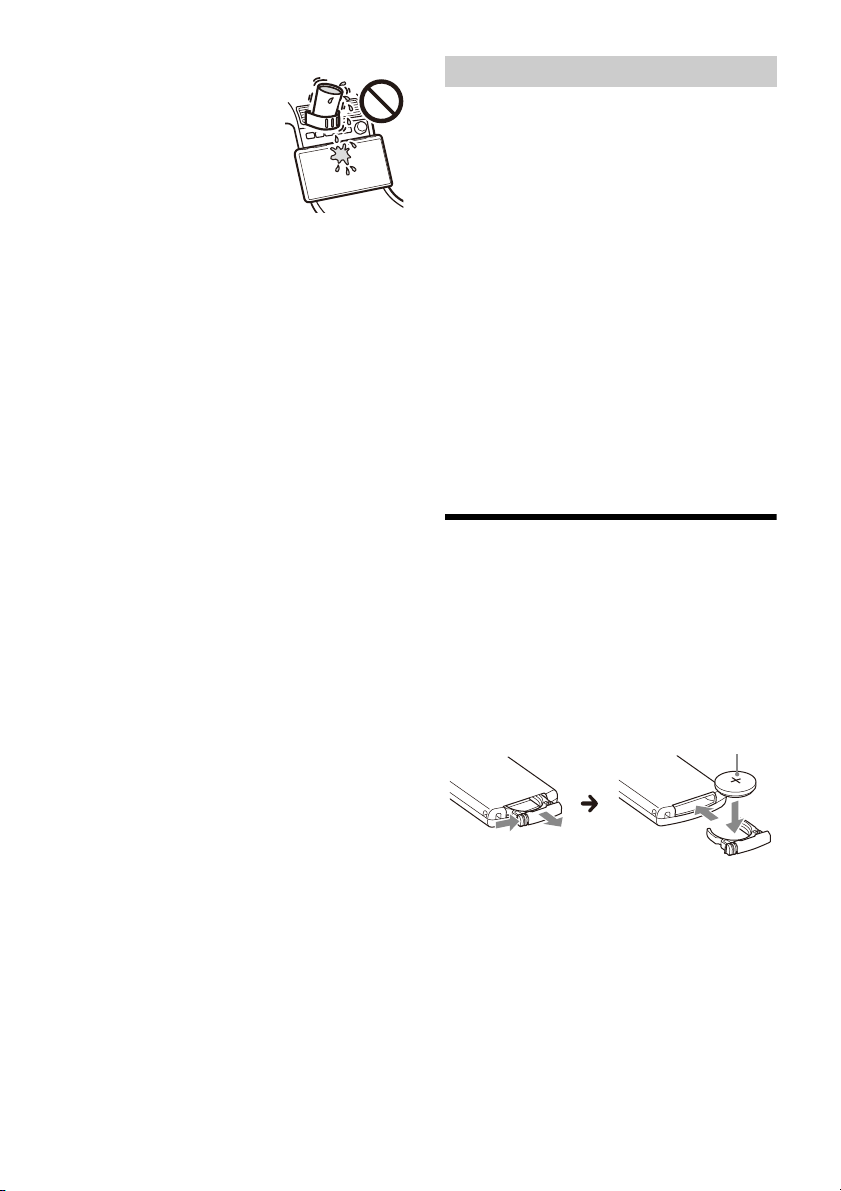
Maintenance
Replacing the lithium battery (CR2025) of the
remote commander
When the battery becomes weak, the range of the
remote commander becomes shorter.
CAUTION
Danger of explosion if battery is incorrectly
replaced. Replace only with the same or equivalent
type.
Note on the lithium battery
Keep the lithium battery out of the reach of children. Should
the battery be swallowed, immediately consult a doctor.
About iPhone
+ side up
Lithium battery (CR2025)
10GB
Specifications
Monitor section
Display type: Wide LCD color monitor
Dimensions: 10.1 in/257 mm
System: TFT active matrix
Number of pixels:
2,764,800 pixels (1280 × 3 (RGB) × 720)
Radio section
FM
Tuning range:
87.5 MHz – 108.0 MHz (at 50 kHz step)
87.5 MHz – 108.0 MHz (at 100 kHz step)
FM tuning step:
50 kHz/100 kHz switchable
Usable sensitivity: 7 dBf
Signal-to-noise ratio: 70 dB (mono)
Separation at 1 kHz: 45 dB
AM
Tuning range:
531 kHz – 1,602 kHz (at 9 kHz step)
530 kHz – 1,710 kHz (at 10 kHz step)
AM tuning step:
9 kHz/10 kHz switchable
Sensitivity: 32 μV
USB player section
Interface: USB Type-C® (Hi-speed)
Maximum current: 3.0 A
BLUETOOTH section
Communication System:
BLUETOOTH Standard version 5.0
Output:
BLUETOOTH Standard Power Class 1
(Max. Conducted +7.5 dBm)
Maximum communication range*1:
Line of sight approx. 10 m (33 ft)
Frequency band:
2.4 GHz band (2.4000 GHz – 2.4835 GHz)
Modulation method: FHSS
Compatible BLUETOOTH Profiles*2:
A2DP (Advanced Audio Distribution Profile) 1.3.1
AVRCP (Audio Video Remote Control Profile) 1.6.1
HFP (Handsfree Profile) 1.7.1
PBAP (Phone Book Access Profile) 1.2
Corresponding codec: SBC, AAC, LDAC™
*1 The actual range will vary depending on factors such as
obstacles between devices, magnetic fields around a
microwave oven, static electricity, reception sensitivity,
antenna (aerial) performance, operating system,
software application, etc.
*2 BLUETOOTH standard profiles indicate the purpose of
BLUETOOTH communication between devices.
Wi-Fi section
Compatible standards:
IEEE802.11 a/n/ac
Radio frequency:
5 GHz band (5.725 GHz - 5.850 GHz)
Output power:
Max. conducted 10 dBm
Frequency Tolerance: 20 ppm
Power amplifier section
Outputs: Speaker outputs
Speaker impedance: 4 Ω – 8 Ω
Maximum power output: 55 W × 4 (at 4 Ω)
General
Power requirements:
12 V DC car battery (negative ground (earth))
Rated current consumption: 10 A
Dimensions (maximum):
Approx. 271 mm × 171 mm × 247 mm
(10 3/4in × 6 3/4in × 9 3/4in) (w/h/d)
Mounting dimensions:
Approx. 182 mm × 53 mm × 160 mm
(7 1/4in × 2 1/8in × 6 3/8in) (w/h/d)
Mass: Approx. 2.5 kg (5 lb 9 oz)
Package contents:
Main unit (1)
Parts for installation and connections (1 set)
Remote commander (1): RM-X400
Ask the dealer for detailed information.
Design and specifications are subject to change
without notice.
11GB
The Bluetooth® word mark and logos are registered
trademarks owned by Bluetooth SIG, Inc. and any
use of such marks by Sony Group Corporation and
its subsidiaries is under license. Other trademarks
and trade names are those of their respective
owners.
Windows Media is either a registered trademark or
trademark of Microsoft Corporation in the United
States and/or other countries.
This product is protected by certain intellectual
property rights of Microsoft Corporation. Use or
distribution of such technology outside of this
product is prohibited without a license from
Microsoft or an authorized Microsoft subsidiary.
Apple and iPhone are trademarks of Apple Inc.,
registered in the U.S. and other countries.
Apple CarPlay is a trademark of Apple Inc.
IOS is a trademark or registered trademark of Cisco
in the U.S. and other countries and is used under
license.
Android and Android Auto are trademarks of
Google LLC.
The Wi-Fi CERTIFIED™ Logo is a certification mark of
Wi-Fi Alliance®.
LDAC and LDAC logo are trademarks of Sony
Corporation.
USB Type-C® and USB-C® are registered trademarks
of USB Implementers Forum.
All other trademarks are trademarks of their
respective owners.
Copyrights
12GB
Cautions
• Do not install this unit in a car that has no ACC
position. The display of the unit does not turn off
even after turning the ignition off, and this causes
battery drain.
• Run all ground (earth) leads to a common
ground (earth) point.
• Do not get the leads trapped under a screw or
caught in moving parts (e.g., seat railing).
• Before making connections, turn the car ignition
off to avoid short circuits.
• Connect the yellow and red power supply leads
only after all other leads have been connected.
• Be sure to insulate any loose unconnected leads
with electrical tape for safety.
• Choose the installation location carefully so that
the unit will not interfere with normal driving
operations.
• Avoid installing the unit in areas subject to dust,
dirt, excessive vibration, or high temperature, such
as in direct sunlight or near heater ducts.
• Use only the supplied mounting hardware for a
safe and secure installation.
• Be sure to use the supplied USB extension cables.
• This unit may not be installed properly depending
on the car type. For details on the mounting
space, see “Ensuring the mounting location of the
unit” (page 13).
• To avoid injury, be careful not to drop the display
during installation.
• When installing, be careful not to cut off your
fingers with the metal parts of the brackets and
mounting base.
• Do not pinch your fingers when attaching the
display to the unit.
• Do not install the unit in a position where the unit
interferes with driving operations (such as in
positions where the shift lever hits the unit, or the
hazard button cannot be pressed).
• When using the unit for a long period of time,
there may be a possibility that the screws securing
the display may come loose. Periodically tighten
these screws.
• Do not make any changes or modifications to the
unit other than those described in this manual.
Note on the power supply lead (yellow)
When connecting this unit in combination with other stereo
components, the amperage rating of the car circuit to which
the unit is connected must be higher than the sum of each
component’s fuse amperage rating.
Note on installing in cars with a start-stop system
The unit may restart when starting the engine from start-
stop. In this case, turn off the start-stop system of your car.
Note on installing in cars with electric parking brake
system
For cars with electric parking brakes, some related functions
(such as video blocking function) may not work properly.
Mounting angle adjustment
Adjust the mounting angle to less than 30°.
Connection/Installation
13GB
• Make sure that the distance from the front surface
(reference surface) of the mounted unit to the
surface of your car’s center cluster is within 22 mm
(7/8in). If exceeded, the unit cannot be installed
properly.
• For your safety, adjust the mounting location of
the unit so that it does not interfere with driving
operations such as button (switch) or shift lever
operations.
Ensuring the mounting location of the
unit
Before installing the unit, consult the installer for
details on the installation of the unit and the
display.
ɸ
ɹ
Front surface of the unit
(reference surface)
Center cluster panel of
your car
Screw hole positions
(for securing the display and the unit)
22 mm (7/8in) 42 mm to 62 mm (1 11/16 in to 2 1/2in)
ɻ
ɼ
ɺ
ɻ
Hidden area even when the display is
slid up or down
Position of the unit (reference position)
60 mm (2 3/8in) 112 mm (4 1/2in) 60 mm (2 3/8in)
ɽɽ
ɽɽ
25 mm (1 in)
14GB
Parts List for Installation
This parts list does not include all the package
contents.
Power supply leads (1) Connection cables
(Audio/Camera) (1)
Mounting screw
(5 × max. 9 mm
(7/32 × max. 3/8in)) (4)
Microphone (1)
Flat-mount base (1) Double-sided tape (1)
USB Type-C extension cable
(1)
USB cable holder (1)
Screw for USB cable holder (1) Cable for steering wheel
remote input (RC-SR1) (1)
Fixing screw
(for the joint cover)
(3 × 8 mm (1/8× 11/32 in)) (1)
Fixing screw
(for the joint part)
(4 × 6 mm (3/16 × 1/4in)) (4)
GPS antenna (aerial) (1) Metal plate (1)
Rear panel cover (2)
15GB
Connection
FUSE 10A
EXT IN 1
EXT IN 2
*3
*3
*3
Camera*1
Rear view
camera*1
from a steering wheel remote
control*6
White
White/black striped
Gray
Gray/black striped
Green
Green/black striped
Purple
Purple/black striped
Black
Yellow
Red
Blue/white striped
Orange/white striped
Light green
Purple/white striped
from a car antenna (aerial)*7
For details, see “Making
connections” (page 16).
Front speaker*1*2
Rear speaker*1*2

*8*9
*3

*10
Pink *10

Smartphone, USB device (for audio/
video playback)*1
Camera*1
*3
*3
*4
*4
*4
*5
*5
• To prevent short circuits, insulate leads with a cover or tape.
• Note that the unit may be damaged if it is connected incorrectly or by short circuits at the leads.
16GB
*1 Not supplied
*2 Speaker impedance: 4 Ω to 8 Ω × 4
*3 RCA pin cord (not supplied)
*4 Power amplifier (not supplied)
*5 Subwoofer (not supplied)
*6 Depending on the type of car, use an adaptor for a
steering wheel remote control (not supplied). For details
on using the steering wheel remote control, see “Using
the steering wheel remote control” (page 18).
*7 Depending on the type of car, use an adaptor (not
supplied) if the antenna (aerial) connector does not fit.
*8 Whether in use or not, route the microphone input cord
so it does not interfere with driving operations. Secure
the cord with a clamp, etc., if it is installed around your
feet.
*9
For details on installing the microphone, see “Installing
the microphone” (page 17).
*10
Connect when using Apple CarPlay with a wireless
connection.
To a common ground (earth) point
First connect the black ground (earth) lead then
connect the yellow and red power supply leads.
To the +12 V power terminal which is
energized at all times
Be sure to first connect the black ground (earth)
lead to a common ground (earth) point.
To the +12 V power terminal which is
energized when the ignition switch is set to
the accessory position
Be sure to first connect the black ground (earth)
lead to a common ground (earth) point.
To the power antenna (aerial) control lead or
the power supply lead of the antenna (aerial)
booster
It is not necessary to connect this lead if there is
no power antenna (aerial) or antenna (aerial)
booster, or with a manually-operated telescopic
antenna (aerial).
To AMP REMOTE IN of an optional power
amplifier
This connection is only for amplifiers and a
power antenna (aerial). Connecting any other
system may damage the unit.
Note
It will take about 10 seconds to shut down the output of
REM OUT after the unit is turned off.
To a car’s illumination signal
Be sure to first connect the black ground (earth)
lead to a common ground (earth) point.
To the parking brake switch lead
The mounting position of the parking brake
switch lead depends on your car.
Be sure to connect the parking brake lead (light
green) of the power supply leads to the
parking brake switch lead.
To the +12 V power terminal of the car’s rear
lamp lead (only when connecting the rear
view camera)
To a car’s speed pulse signal
When using Apple CarPlay with a wireless
connection, it is necessary to connect to keep
the accurate location of your car.
The mounting position of the speed pulse
output lead depends on your car.
To an interruption signal (+3.3 V to +12 V) to
display the picture from CAMERA IN 1 and
CAMERA IN 2
Note
REVERSE IN, EXT IN 1, and EXT IN 2 interrupt detections
have the following priority levels.
REVERSE IN always has priority; if both EXT IN 1 and
EXT IN 2 occur at the same time, EXT IN 1 has higher
priority.
Camera Connection
Installation of cameras (not supplied) is required
before use.
Connect the camera power cord (lead) to the
accessory power terminal.
Memory hold connection
When the yellow power supply lead is connected,
power will always be supplied to the memory
circuit even when the ignition switch is turned off.
Speaker connection
• Before connecting the speakers, turn the unit off.
• Use speakers with an impedance of 4 Ω to 8 Ω,
and with adequate power handling capacities to
avoid damage.
Making connections
Parking brake switch lead
Hand brake type Foot brake type
17GB
To capture your voice during handsfree calling, you
need to install the microphone .
Cautions
• It is extremely dangerous if the cord becomes
wound around the steering column or gearstick.
Be sure to keep it and other parts from interfering
with your driving operations.
• If airbags or any other shock-absorbing
equipment are in your car, contact the store where
you purchased this unit or the car dealer before
installation.
Notes
• When mounting on the dashboard, remove the visor clip
carefully from the microphone , then attach the flat-
mount base to the microphone .
• Before attaching the double-sided tape , clean the
surface of the dashboard with a dry cloth.
A
• Choose a location where no obstacle blocks GPS
satellite reception so as to achieve the best
reception.
• Make sure the GPS antenna (aerial) does not
interfere with the operation of car equipment.
• Some types of front windshields (windscreens)
block GPS satellite radio waves. Make sure the
signal reception is not blocked.
• When using Apple CarPlay with a wireless
connection, make sure the GPS antenna (aerial) 
is connected.
1Decide the installation location on the
dashboard, then clean the attachment
surface.
Choose a flat surface where:
the GPS antenna (aerial) can be positioned
horizontally.
operation of the passenger-side airbag is not
impeded.
GPS satellite reception is not blocked by
anything inside the car or the windshield
(windscreen) wipers.
2Remove the tape of the metal plate , then
attach it on the dashboard.
3Remove the tape of the GPS antenna (aerial)
, then attach it on the metal plate .
Cautions
• It is extremely dangerous if the cord becomes
wound around the steering column or gearstick.
Be sure to keep it and other parts from interfering
with your driving operations.
• If airbags or any other shock-absorbing
equipment are in your car, contact the store where
you purchased this unit or the car dealer before
installation.
Notes
• Be sure to use the metal plate , otherwise signal
reception may be poor.
• Do not install the GPS antenna (aerial) close to other
electrical equipment, otherwise signal reception may be
unstable.
• If the surface of the metal plate is cold, the tape may
not stick firmly. Warm up its surface with a hair dryer, etc.,
before applying the tape.
• If there is no flat surface on which to install the GPS
antenna (aerial) , bend the metal plate to fit a curved
surface before installing.
Installing the microphone
Installing the GPS antenna (aerial)


Clip (not supplied)




18GB
When using the steering wheel remote
control
Installation of the connection cable RC-SR1 is
required before use.
1Select [Settings] [System] [Steering
Wheel Settings].
2Set the [Custom] switch to [On].
You can make the registration to enable the
steering wheel remote control.
When the registration is complete, the steering
wheel remote control becomes available.
Notes on installing the connection cable
RC-SR1 
• Refer to the support site for details, then connect
each lead properly to the appropriate leads.
Making an improper connection may damage the
unit.
URL: https://www.sony-asia.com/support
• Consulting the dealer or an experienced
technician for help is recommended.
When using an adaptor for the steering wheel
remote control
Depending on the type of car, use an adaptor for
the steering wheel remote control (not supplied).
1Select [Settings] [System] [Steering
Wheel Settings].
2Set the [Custom] switch to [Off].
The adaptor for the steering wheel remote
control is enabled.
Installation
To install the unit and the display securely, be sure
to follow the steps to in order.
Before mounting the unit (page 18)
Mounting the unit in the dashboard (page 19)
Setting up the display (page 19)
Making sure the mounting positions of the
display (page 22)
Attaching the display to the unit (page 22)
For your safety
After mounting the display to the unit, make sure
that the display does not interfere with normal
driving operations such as blocking the driver’s
view or getting the cables tangled.
Before mounting the unit in the dashboard, arrange
the USB extension cables.
1Connect the USB Type-C extension cable 
to the USB port.
2Tighten the screw firmly on the USB cable
holder to secure the USB Type-C
extension cable .
Using the steering wheel remote
control
GND
Input 1
Input 2
REMOTE IN
Black
Green
Brown
Before mounting the unit




19GB
3Route the USB Type-C extension cable 
inside the dashboard.
Using the mounting brackets supplied
with your car
You may not be able to install this unit in some
makes of Japanese cars. In such a case, consult your
Sony dealer.
Example
Note
To prevent malfunction, install only with the mounting
screws .
The mounting positions of the display can be
adjusted.
Adjusting the depth of the display
position
1Loosen the 3 pre-installed screws for depth
adjustment (on top and both sides).
Slightly loosen the screws until you can slide the
connector bracket. Do not remove the screws
from the bracket. Doing so may damage the
parts.
Mounting the unit in the dashboard

to dashboard/center console
Bracket
Bracket
Existing parts supplied
with your car


Setting up the display
Depth
(within 20 mm
(13/16 in), in 3 steps)
Height
(within 60 mm
(2 3/8in), in 7 steps)
Angle
(-10° to +10°, in 3
steps)
Width
(within 25 mm (1 in), in 5 steps)
Pre-installed screws
20GB
2Slide the connector bracket to decide the
appropriate depth position.
Adjustable depth: within 20 mm (13/16 in) (), in
3 steps, in 10 mm (13/32 in) pitch ().
Bracket positions 1 to 3 for the display:
1: Slide-out position
2: Intermediate position
3: Slide-in position
3At the desired position, tighten the 3 screws
firmly to secure the connector bracket.
Tighten the screws firmly.
When you tighten a screw, be careful not to
apply too much torque as doing so may damage
the screw (the torque value should be from
1.5 N•m to 2.0 N•m).
Adjusting the height of the display
position
1Remove the 4 pre-installed screws for
height adjustment (on both sides).
2Slide the connector bracket up or down to
decide the appropriate height position.
Adjustable height: within 60 mm (2 3/8in) (),
in 7 steps, in 10 mm (13/32 in) pitch ().
3At the desired position, tighten the 4 screws
firmly to secure the connector bracket.
Tighten the screws firmly.
When you tighten a screw, be careful not to
apply too much torque as doing so may damage
the screw (the torque value should be from
1.5 N•m to 2.0 N•m).
Adjusting the display angle (tilt)
1Remove the 2 pre-installed screws for angle
adjustment (on both sides).
ɹ
ɸ
ɹ
321
Pre-installed screws
ɸ
ɹ
ɹ
ɹ
ɹ
Pre-installed screws

Other manuals for XAV-9500ES

3

Other Sony Stereo Receiver manuals

Sony STR-DA4400ES User manual

Sony

Sony STR-DA4400ES User manual

Sony STR-DE595 User manual

Sony

Sony STR-DE595 User manual

Sony XAV-712HD User manual

Sony

Sony XAV-712HD User manual

Sony STR-D550Z User manual

Sony

Sony STR-D550Z User manual

Sony STR-DE897 User manual

Sony

Sony STR-DE897 User manual

Sony STR-SE381 User manual

Sony

Sony STR-SE381 User manual

Sony STR-AV880 User manual

Sony

Sony STR-AV880 User manual

Sony STR-K660P - Fm Stereo/fm-am Receiver User manual

Sony

Sony STR-K660P - Fm Stereo/fm-am Receiver User manual

Sony HCD-D115 User manual

Sony

Sony HCD-D115 User manual

Sony STR-DE335 - Fm Stereo/fm-am Receiver User manual

Sony

Sony STR-DE335 - Fm Stereo/fm-am Receiver User manual

Sony STR-DE445 - Fm Stereo/fm-am Receiver User manual

Sony

Sony STR-DE445 - Fm Stereo/fm-am Receiver User manual

Sony STR-DE935 User manual

Sony

Sony STR-DE935 User manual

Sony STR-DA2ES - Fm Stereo/fm-am Receiver User manual

Sony

Sony STR-DA2ES - Fm Stereo/fm-am Receiver User manual

Sony Sports Walkman SRF-87 User manual

Sony

Sony Sports Walkman SRF-87 User manual

Sony STR-DE425 - Fm Stereo/fm-am Receiver User manual

Sony

Sony STR-DE425 - Fm Stereo/fm-am Receiver User manual

Sony STR-DE425 - Fm Stereo/fm-am Receiver User manual

Sony

Sony STR-DE425 - Fm Stereo/fm-am Receiver User manual

Sony STR-SL5 User manual

Sony

Sony STR-SL5 User manual

Sony STR-AZ1000ES User manual

Sony

Sony STR-AZ1000ES User manual

Sony STR-V333ES - Fm Stereo/fm-am Receiver User manual

Sony

Sony STR-V333ES - Fm Stereo/fm-am Receiver User manual

Sony STR-6055 Setup guide

Sony

Sony STR-6055 Setup guide

Sony STR-DE975 User manual

Sony

Sony STR-DE975 User manual

Sony XAV-V10BT User manual

Sony

Sony XAV-V10BT User manual

Sony ICF-5900W User manual

Sony

Sony ICF-5900W User manual

Sony STR-GA7ES User manual

Sony

Sony STR-GA7ES User manual

Popular Stereo Receiver manuals by other brands

Realistic STA-115 Service manual

Realistic

Realistic STA-115 Service manual

Denon AVR-X4700H quick start guide

Denon

Denon AVR-X4700H quick start guide

Onkyo TX-RZ1100-B Basic Manual

Onkyo

Onkyo TX-RZ1100-B Basic Manual

Aiwa NSX-AV240 Simple manual

Aiwa

Aiwa NSX-AV240 Simple manual

Denon AVR-2308CI owner's manual

Denon

Denon AVR-2308CI owner's manual

Denon DRA-37 - AM/FM Stereo Receiver operating instructions

Denon

Denon DRA-37 - AM/FM Stereo Receiver operating instructions

Pioneer SX-255R Service manual

Pioneer

Pioneer SX-255R Service manual

Pioneer VSX-95 operating instructions

Pioneer

Pioneer VSX-95 operating instructions

Pioneer VSX-604S operating instructions

Pioneer

Pioneer VSX-604S operating instructions

Sansui 8080 Operatng Instructions

Sansui

Sansui 8080 Operatng Instructions

Denon AVR-S500BT owner's manual

Denon

Denon AVR-S500BT owner's manual

Pioneer VSX-D908TX Service manual

Pioneer

Pioneer VSX-D908TX Service manual

Pioneer SPH-EVO64DAB installation manual

Pioneer

Pioneer SPH-EVO64DAB installation manual

Technics SA-DA10 Operating instrutions

Technics

Technics SA-DA10 Operating instrutions

Aiwa AV-D78 operating instructions

Aiwa

Aiwa AV-D78 operating instructions

Technics SA-203 Service manual

Technics

Technics SA-203 Service manual

Aiwa AD-1800 Service manual

Aiwa

Aiwa AD-1800 Service manual

Kaito KA801 Operation manual

Kaito

Kaito KA801 Operation manual

manuals.online logo
manuals.online logoBrands
  • About & Mission
  • Contact us
  • Privacy Policy
  • Terms and Conditions

Copyright 2025 Manuals.Online. All Rights Reserved.