Sony XAV-AX210 User manual

Sony Video & Sound Products Inc.
SERVICE MANUAL
Conditions of Use:
(1) Please use this information only for the purpose of performing repair, maintenance and/or configuration services of the Sony products (hereinafter the “Repair services”) under the ser-
vice agreement entered into with the Sony group company (hereinafter the “Service agreement”). Using this information for any purpose other than the purpose described foregoing is
forbidden.
(2) Only the Authorized Servicer’s officers, employees or subcontractors (including their officers and employees) whose duties justify a need-to-know and who have agreed to hold
confidential this information (collectively hereinafter the “Permitted users”) are permitted to access and use this information. To disclose or disseminate to any person other than the
Permitted users is forbidden.
(3) Destroy or erase any and all portion of this information promptly in an irrecoverable and secure fashion after achieving the purpose described in Section (1) above.
(4) Do not copy, replicate, reproduce, alter, translate, transmit, sell, lease, or distribute this information in whole or in part without the prior written permission of the author.
(Notwithstanding foregoing, it is permitted to copy and distribute this information to the Permitted users.)
(5) Please notify immediately any leakage, loss, theft, misappropriation, or other misuse of this information by e-mail to the following address:
(6) In addition to the above, the terms and conditions of the Service agreement shall be applied to using this information.
Revision of Information:
This information may be changed or updated at any time without any prior notice. Please confirm that this information is up-to-date before using it.
Sony CONFIDENTIAL
For Authorized Servicer
9-896-545-01
2018I33-1
© 2018.09
XAV-AX210
SYSSET
2018/09/1222:50:21(GMT+09:00)

SERVICE MANUAL
Sony CONFIDENTIAL
For Authorized Servicer
SPECIFICATIONS
AV RECEIVER
US Model
Canadian Model
Ver. 1.0 2018.09
Model Name Using Similar Mechanism XAV-AX200
Mechanism Type DL-C35D2
XAV-AX210
FOR THE CUSTOMERS IN THE USA. NOT
APPLICABLE IN CANADA, INCLUDING IN THE
PROVINCE OF QUEBEC.
POUR LES CLIENTS AUX ÉTATS-UNIS. NON
APPLICABLE AU CANADA, Y COMPRIS LA
PROVINCE DE QUÉBEC.
AUDIO POWER SPECIFICATIONS
CTA2006 Standard
Power Output: 20 Watts RMS × 4 at
4 Ohms < 1% THD+N
SN Ratio: 80 dBA (reference: 1 Watt into
4 Ohms)
Monitor section
Display type: Wide LCD color monitor
Dimensions: 6.4 in
System: TFT active matrix
Number of pixels:
1,152,000 pixels (800 × 3 (RGB) × 480)
Color system:
PAL/NTSC/SECAM/PAL-M automatic select for
CAMERA IN terminal
Tuner section
FM
Tuning range: 87.5 MHz – 107.9 MHz
Antenna (aerial) terminal:
External antenna (aerial) connector
Intermediate frequency: 150 kHz
Usable sensitivity: 10 dBf
Selectivity: 70 dB at 400 kHz
Signal-to-noise ratio: 70 dB (mono)
Separation at 1 kHz: 30 dB
Frequency response: 20 Hz – 15,000 Hz
AM
Tuning range: 530 kHz – 1,710 kHz
Antenna (aerial) terminal:
External antenna (aerial) connector
Intermediate frequency:
9,267.5 kHz or 9,257.5 kHz/5 kHz
Sensitivity: 44 μV
DVD/CD Player section
Signal-to-noise ratio: 80 dB
Frequency response: 20 Hz – 20,000 Hz
Wow and flutter: Below measurable limit
Harmonic distortion: 0.05%
Region code: Labeled on the bottom of the unit
USB player section
Interface: USB (High-speed)
Maximum current: 1.5 A
Wireless communication
Communication System:
BLUETOOTH Standard version 2.1
Output:
BLUETOOTH Standard Power Class 2
(Max. +4 dBm)
Maximum communication range*1:
Line of sight approx. 10 m (33 ft)
Frequency band:
2.4 GHz band (2.4000 GHz – 2.4835 GHz)
Modulation method: FHSS
Compatible BLUETOOTH Profiles*2:
A2DP (Advanced Audio Distribution Profile) 1.2
AVRCP (Audio Video Remote Control Profile) 1.5
HFP (Handsfree Profile) 1.6
PBAP (Phone Book Access Profile) 1.1
Corresponding codec: SBC (.sbc)
*1 The actual range will vary depending on factors such as
obstacles between devices, magnetic fields around a
microwave oven, static electricity, reception sensitivity,
antenna (aerial)’s performance, operating system,
software application, etc.
*2 BLUETOOTH standard profiles indicate the purpose of
BLUETOOTH communication between devices.
Power amplifier section
Outputs: Speaker outputs
Speaker impedance: 4 Ω – 8 Ω
Maximum power output: 55 W × 4 (at 4 Ω)
General
Outputs:
Audio output terminals (FRONT, REAR, SUB)
Power antenna (aerial)/Power amplifier control
terminal (REM OUT)
Inputs:
SiriusXM input terminal
Illumination control terminal
Steering control input terminal
Antenna (aerial) input terminal
Microphone input terminal
Parking brake control terminal
Reverse input terminal
Camera input terminals
USB port
iDataLink Maestro input terminal
Power requirements: 12 V DC car battery
(negative ground (earth))
Rated current consumption: 10 A
Dimensions: Approx. 178 mm × 102 mm × 168 mm
(7 1/8in × 4 1/8in × 6 5/8in) (w/h/d)
Mounting dimensions:
Approx. 178 mm × 100 mm × 164 mm
(7 1/8in × 4 in × 6 1/2in) (w/h/d)
Mass: Approx. 1.7 kg (3 lb 12 oz)
Package contents:
Main unit (1)
Parts for installation and connections (1 set)
Remote Commander (1): RM-X170
Microphone (1)
Design and specifications are subject to change
without notice.
Region code
The region system is used to protect software
copyrights.
The region code is located on the bottom of the
unit, and only DVDs labeled with an identical region
code can be played on this unit.
DVDs labeled can also be played.
If you try to play any other DVD, the message [Disc
playback prohibited by region code.] will appear on
the monitor screen. Depending on the DVD, no
region code may be labeled even though playing
the DVD is prohibited by area restrictions.
SYSSET
2018/09/1222:50:21(GMT+09:00)

XAV-AX210
3
Sony CONFIDENTIAL
For Authorized Servicer
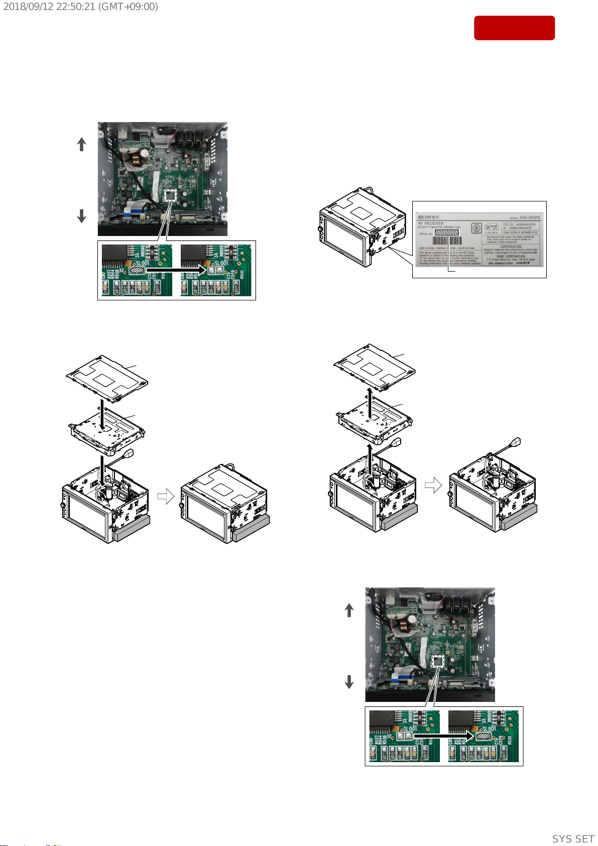
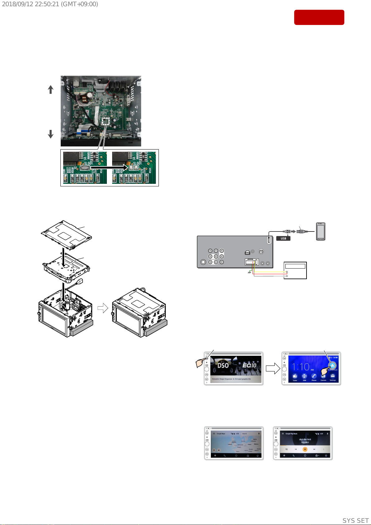
FLEXIBLE CIRCUIT BOARD REPAIRING
• Keep the temperature of soldering iron around 270 °C during
repairing.
• Do not touch the soldering iron on the same conductor of the
circuit board (within 3 times).
• Be careful not to apply force on the conductor when soldering or
unsoldering.
SAFETY-RELATED COMPONENT WARNING!
COMPONENTS IDENTIFIED BY MARK 0OR DOTTED LINE
WITH MARK 0ON THE SCHEMATIC DIAGRAMS AND IN THE
PARTS LIST ARE CRITICAL TO SAFE OPERATION.
REPLACE THESE COMPONENTS WITH SONY PARTS WHOSE
PART NUMBERS APPEAR AS SHOWN IN THIS MANUAL OR
IN SUPPLEMENTS PUBLISHED BY SONY.
CAUTION
Use of controls or adjustments or performance of procedures other
than those specified herein may result in hazardous radiation ex-
posure.
1. SERVICING NOTES ................................................ 4
2. GENERAL ..................................................................... 13
3. DISASSEMBLY
3-1. Disassembly Flow.............................................................. 15
3-2. Mini Fuse (Blade Type), Top Cover .................................. 15
3-3. DVD Deck Assy................................................................. 16
3-4. USB Cable ......................................................................... 16
3-5. Front Panel Block, Chassis Block...................................... 17
3-6. Fan ..................................................................................... 17
3-7. MAIN Board ...................................................................... 18
3-8. BT-ANT Cover, Panel Bracket .......................................... 18
3-9. Knob Assy.......................................................................... 19
3-10. Disc Guide Assy................................................................. 19
3-11. TFT Board-1 ...................................................................... 20
3-12. TFT Board-2 ...................................................................... 21
3-13 BT Antenna, TFT (6.4), Touch Panel................................. 22
3-14. Service Position ................................................................. 22
4. ELECTRICAL ADJUSTMENT ............................. 23
5. DIAGRAMS
5-1. Block Diagram - OVERALL Section -.............................. 24
5-2. Block Diagram - POWER SUPPLY Section -................... 25
5-3. Printed Wiring Board - TUNER Board - ........................... 27
5-4. Schematic Diagram - TUNER Board - .............................. 27
5-5. Printed Wiring Board - SXM/MAESTRO Board -............ 28
5-6. Schematic Diagram - SXM/MAESTRO Board - .............. 28
5-7. Printed Wiring Board - SERVO Board -............................ 29
5-8. Schematic Diagram - SERVO Board -............................... 30
5-9. Printed Wiring Board - MAIN Board (Side A) - ............... 31
5-10. Printed Wiring Board - MAIN Board (Side B) - ............... 32
5-11. Schematic Diagram - MAIN Board (1/3) -........................ 33
5-12. Schematic Diagram - MAIN Board (2/3) -........................ 34
5-13. Schematic Diagram - MAIN Board (3/3) -........................ 35
5-14. Printed Wiring Board - TFT Board -.................................. 36
5-15. Schematic Diagram - TFT Board (1/8) -............................ 37
5-16. Schematic Diagram - TFT Board (2/8) -............................ 38
5-17. Schematic Diagram - TFT Board (3/8) -............................ 39
5-18. Schematic Diagram - TFT Board (4/8) -............................ 40
5-19. Schematic Diagram - TFT Board (5/8) -............................ 41
5-20. Schematic Diagram - TFT Board (6/8) -............................ 42
5-21. Schematic Diagram - TFT Board (7/8) -............................ 43
5-22. Schematic Diagram - TFT Board (8/8) -............................ 44
6. EXPLODED VIEWS
6-1. Overall Section .................................................................. 45
6-2. Chassis Section .................................................................. 46
6-3. Front Panel Section............................................................ 47
7. ELECTRICAL PARTS LIST ................................. 48
8. ACCESSORIES .......................................................... 49
TABLE OF CONTENTS
SiriusXM Connect Vehicle Tuner and Subscription
sold separately.
www.siriusxm.com
Sirius, XM and all related marks and logos are
trademarks of Sirius XM Radio Inc. All rights
reserved.
US and foreign patents licensed from Dolby
Laboratories.
MPEG Layer-3 audio coding technology and patents
licensed from Fraunhofer IIS and Thomson.
Manufactured under license from Dolby
Laboratories. Dolby, Dolby Audio, and the double-D
symbol are trademarks of Dolby Laboratories.
The Bluetooth® word mark and logos are registered
trademarks owned by the Bluetooth SIG, Inc. and
any use of such marks by Sony Corporation is under
license. Other trademarks and trade names are
those of their respective owners.
Windows Media is either a registered trademark or
trademark of Microsoft Corporation in the United
States and/or other countries.
This product is protected by certain intellectual
property rights of Microsoft Corporation. Use or
distribution of such technology outside of this
product is prohibited without a license from
Microsoft or an authorized Microsoft subsidiary.
“DVD VIDEO” is a trademark.
Apple, iPhone, and Lightning are trademarks of
Apple Inc., registered in the U.S. and other
countries.
Apple CarPlay is a trademark of Apple Inc.
IOS is a trademark or registered trademark of Cisco
in the U.S. and other countries and is used under
license.
Android, Android Auto, Google and Google Play are
trademarks of Google LLC.
This product uses font data which is licensed to
Sony owned by Monotype Imaging Inc.
Such font data shall be used solely in connection
with this product.
Copyrights THIS PRODUCT IS LICENSED UNDER THE MPEG-4
VISUAL PATENT PORTFOLIO LICENSE FOR THE
PERSONAL AND NON-COMMERCIAL USE OF A
CONSUMER FOR DECODING VIDEO IN COMPLIANCE
WITH THE MPEG-4 VISUAL STANDARD (“MPEG-4
VIDEO”) THAT WAS ENCODED BY A CONSUMER
ENGAGED IN A PERSONAL AND NONCOMMERCIAL
ACTIVITY AND/OR WAS OBTAINED FROM A VIDEO
PROVIDER LICENSED BY MPEG LA TO PROVIDE
MPEG-4 VIDEO.
NO LICENSE IS GRANTED OR SHALL BE IMPLIED FOR
ANY OTHER USE.
ADDITIONAL INFORMATION INCLUDING THAT
RELATING TO PROMOTIONAL, INTERNAL AND
COMMERCIAL USES AND LICENSING MAY BE
OBTAINED FROM MPEG LA, LLC. SEE
HTTP://WWW.MPEGLA.COM
THIS PRODUCT IS LICENSED UNDER THE AVC PATENT
PORTFOLIO LICENSE FOR THE PERSONAL AND NON-
COMMERCIAL USE OF A CONSUMER TO
(i)ENCODE VIDEO IN COMPLIANCE WITH THE AVC
STANDARD (“AVC VIDEO”)
AND/OR
(ii)DECODE AVC VIDEO THAT WAS ENCODED BY A
CONSUMER ENGAGED IN A PERSONAL AND
NON-COMMERCIAL ACTIVITY AND/OR WAS
OBTAINED FROM A VIDEO PROVIDER LICENSED TO
PROVIDE AVC VIDEO. NO LICENSE IS GRANTED OR
SHALL BE IMPLIED FOR ANY OTHER USE.
ADDITIONAL INFORMATION MAY BE OBTAINED
FROM MPEG LA, L.L.C. SEE
HTTP://WWW.MPEGLA.COM
THIS PRODUCT IS LICENSED UNDER THE AVC PATENT
PORTFOLIO LICENSE AND VC-1 PATENT PORTFOLIO
LICENSE FOR THE PERSONAL AND NON-
COMMERCIAL USE OF A CONSUMER TO DECODE
VIDEO IN COMPLIANCE WITH THE AVC STANDARD
(“AVC VIDEO”) AND/OR THE VC-1 STANDARD (“VC-1
VIDEO”) THAT WAS ENCODED BY A CONSUMER
ENGAGED IN A PERSONAL AND NONCOMMERCIAL
ACTIVITY AND/OR WAS OBTAINED FROM A VIDEO
PROVIDER LICENSED TO PROVIDE AVC VIDEO AND/
OR VC-1 VIDEO. NO LICENSE IS GRANTED OR SHALL
BE IMPLIED FOR ANY OTHER USE. ADDITIONAL
INFORMATION MAY BE OBTAINED FROM MPEG LA,
L.L.C. SEE HTTP://WWW.MPEGLA.COM
All other trademarks are trademarks of their
respective owners.
ATTENTION AU COMPOSANT AYANT RAPPORT
À LA SÉCURITÉ!
LES COMPOSANTS IDENTIFIÉS PAR UNE MARQUE 0SUR
LES DIAGRAMMES SCHÉMATIQUES ET LA LISTE DES
PIÈCES SONT CRITIQUES POUR LA SÉCURITÉ DE FONC-
TIONNEMENT. NE REMPLACER CES COMPOSANTS QUE
PAR DES PIÈCES SONY DONT LES NUMÉROS SONT DON-
NÉS DANS CE MANUEL OU DANS LES SUPPLÉMENTS
PUBLIÉS PAR SONY.
SYSSET
2018/09/1222:50:21(GMT+09:00)

XAV-AX210
4
Sony CONFIDENTIAL
For Authorized Servicer
SECTION 1
SERVICING NOTES
The SERVICING NOTES contains important information for servicing. Be sure to read this section before repairing the unit.
UNLEADED SOLDER
Boards requiring use of unleaded solder are printed with the lead-
free mark (LF) indicating the solder contains no lead.
(Caution: Some printed circuit boards may not come printed with
the lead free mark due to their particular size)
: LEAD FREE MARK
Unleaded solder has the following characteristics.
• Unleaded solder melts at a temperature about 40 °C higher than
ordinary solder.
Ordinary soldering irons can be used but the iron tip has to be
applied to the solder joint for a slightly longer time.
Soldering irons using a temperature regulator should be set to
about 350 °C.
Caution: The printed pattern (copper foil) may peel away if the
heated tip is applied for too long, so be careful!
• Strong viscosity
Unleaded solder is more viscous (sticky, less prone to flow) than
ordinary solder so use caution not to let solder bridges occur
such as on IC pins, etc.
• Usable with ordinary solder
It is best to use only unleaded solder but unleaded solder may
also be added to ordinary solder.
REPLACING THE LITHIUM BATTERY OF THE REMOTE
COMMANDER
Under normal conditions, the battery will last
approximately 1 year. (The service life may be
shorter depending on the conditions of use.)
When the battery becomes weak, the range of the
remote commander becomes shorter.
CAUTION
Danger of explosion if battery is incorrectly
replaced. Replace only with the same or equivalent
type.
Notes on the lithium battery
• Keep the lithium battery out of the reach of children.
Should the battery be swallowed, immediately consult a
doctor.
• Wipe the battery with a dry cloth to ensure good contact.
• Be sure to observe the correct polarity when installing the
battery.
• Do not hold the battery with metallic tweezers, otherwise
a short-circuit may occur.
+ side up
q
IMPORTANT NOTE FOR REPAIRING
This unit might contain individual information that the customer
registered in the replaced old part because it installs the Bluetooth
function.
Therefore, when repairing, because the data that the customer regis-
tered might disappear, get the approval of the customer beforehand.
If any of the following repair is performed, that data disappears.
• Complete TFT board replacing
• Factory reset (Initialize)
Note: Replaced old complete TFT board is destroyed with the hammer,
and throw out it.
ABOUT INSTALLATION OF THIS UNIT FOR WORKING
Due to the structure of the unit, you cannot stably place it on flat
surfaces.
Stabilize the unit by placing a stand, etc. under it that is suitable for
your work.
stand, etc.
SYSSET
2018/09/1222:50:21(GMT+09:00)

XAV-AX210
5
Sony CONFIDENTIAL
For Authorized Servicer
DESTINATION CHECKING METHOD
When replacing the MAIN board, perform works according to the
following procedure.
If the correct destination code is not displayed, it is necessary to set
the destination.
Note 1: Remote commander is necessary for destination checking opera-
tion.
Procedure:
1. After replacing the MAIN board, assemble the main unit to the
normal condition, and connect the regulated DC power supply.
+
–
Regulated DC
power supply
2. Press the [OFF] button on the remote commander to the state
of source off, enter the test mode by pressing the buttons on the
remote commander in order of the [4] t[5] t[0] (press only
the [0] button for two seconds).
(Displayed screen in the above figure are example)
3. Confirm the alphanumeric character of 2 digits of “DEST” on
the screen display is a value of “01”.
Note 2: If “01” is not displayed or another alphanumeric character is dis-
played, perform “DESTINATION SETTING METHOD” on the
right.
DEST : 01
MCU : SONY-ST28-1800615 1.00.01.00
SOC : 1.00.01.00
APP : 180615-1f65bac
SYS : 180615-7004c7f
SDK : 21.5.0.3.0.0.0.0
GUI : 3.15.0
BT Address : fc:4b:bc:f8:69:64
Serial : 3166000701900029
DVD Region: 1
Servo: SAHSWD-ABA-097C
DEST: 01
(Displayed characters/values in the above figure are example)
4. The resetting operation is executed by pressing the reset button
after the confirming ends, then the unit reboots and returns to the
normal condition.
DEST : 01
MCU : SONY-ST28-1800615 1.00.01.00
SOC : 1.00.01.00
APP : 180615-1f65bac
SYS : 180615-7004c7f
SDK : 21.5.0.3.0.0.0.0
GUI : 3.15.0
BT Address : fc:4b:bc:f8:69:64
Serial : 3166000701900029
DVD Region: 1
Servo: SAHSWD-ABA-097C
[Reset] button
(Displayed characters/values in the above figure are example)
5. This completes the destination check work.
DESTINATION SETTING METHOD
After replacing the MAIN board, perform the following procedure,
only when confirm the destination code and the correct destination
code is not displayed.
Note 1: This work is unnecessary if “DESTINATION CHECKING METH-
OD” on the left is performed and the correct destination code is
displayed.
Note 2: Remote commander is necessary for destination setting operation.
Setting procedure:
1. Refer to “3. DISASSEMBLY” on page 15, disassemble until to
the state that side A of MAIN board can be seen.
Note 3: The following is an image view. Be sure to refer to “3. DISASSEM-
BLY” on page 15 for detail.
top cover
mechanism deck
2. Short-circuit the shortland (SL001) on the MAIN board by sol-
dering.
rear
side
front
side
– MAIN board (Side A) –
– Continued on next page –
SYSSET
2018/09/1222:50:21(GMT+09:00)

XAV-AX210
6
Sony CONFIDENTIAL
For Authorized Servicer
3. Connect the power cord to the regulated DC power supply, and
turn the power on this unit.
Note 4: It is not necessary to install the top cover and mechanism deck that
were removed in step 1.
+
–
Regulated DC
power supply
top cover
mechanism deck
4. Press the [OFF] button on the remote commander to the state
of source off, enter the destination setting mode by pressing the
buttons on the remote commander in order of the [4] t[5] t
[6] (press only the [6] button for two seconds).
(Displayed screen in the above figure are example)
5. The following screen is displayed and the destination setting
mode becomes effective.
<DESTINATION SETTING MODE>
0 0 0 0 0 7
UC:*00001 FT(JPN):*00007
(Displayed characters/values in the above figure are example)
6. Input the 6 digits destination code (000001).
Press the [V] or [v] button on the remote commander to select
“0” with the 6th digit and press the [b] button on the remote
commander.
Press the [V] or [v] button on the remote commander to select
“0” with the 5th digit and press the [b] button on the remote
commander.
Press the [V] or [v] button on the remote commander to select
“0” with the 4th digit and press the [b] button on the remote
commander.
Press the [V] or [v] button on the remote commander to select
“0” with the 3rd digit and press the [b] button on the remote
commander.
Press the [V] or [v] button on the remote commander to select
“0” with the 2nd digit and press the [b] button on the remote
commander.
Press the [V] or [v] button on the remote commander to select
“1” with the 1st digit and press the [ENTER] button on the re-
mote commander, then the unit reboots and returns to the normal
condition.
Note 5: The digit return by pressing the [B] button on the remote command-
er.
Note 6: The destination code cannot be inputted by operation of main unit.
Be sure to input the destination code by using the remote commander.
[b] press to
advance the digit.
[B] press to return
the digit.
[V] press to select
the alphanumeric
characters.
[v] press to select
the alphanumeric
characters.
Press [ENTER] by the
1st digit to complete
the setting.
<DESTINATION SETTING MODE>
00 0 0 0 1
UC:*00001 FT(JPN):*00007
0 0 0 0 0 1
1st2nd3rd4th5th6th
6 digits
7. Refer to step 2 and after in “DESTINATION CHECKING
METHOD” on page 5, and confirm a correct destination was set.
8. Disconnect the power cord from the regulated DC power supply,
and turn the power off this unit.
+
–
Regulated DC
power supply
– Continued on next page –
SYSSET
2018/09/1222:50:21(GMT+09:00)

XAV-AX210
7
Sony CONFIDENTIAL
For Authorized Servicer
9. Unsolder the shortland (SL001) on the MAIN board short-cir-
cuited in step 2, and open the short-circuit.
Note 7: Be sure to open the short-circuit of shortland (SL001).
rear
side
front
side
– MAIN board (Side A) –
10. Install the top cover and mechanism deck removed in step 1.
Note 8: The following is an image view. Be sure to refer to “3. DISASSEM-
BLY” on page 15 for detail.
top cover
mechanism deck
11. Complete the destination setting operation.
SERIAL NUMBER WRITING METHOD
When the MAIN board is replaced, be sure to serial number writ-
ing work is necessary. Perform works according to the following
procedure.
Note 1: Remote commander is necessary for serial number writing opera-
tion.
Serial number writing procedure:
1. Take a memorandum of the serial number on the bottom of this
unit.
Serial number
MODEL NUMBER LABEL
2. Refer to “3. DISASSEMBLY” on page 15, disassemble until to
the state that side A of MAIN board can be seen.
Note 2: The following is an image view. Be sure to refer to “3. DISASSEM-
BLY” on page 15 for detail.
top cover
mechanism deck
3. Short-circuit the shortland (SL001) on the MAIN board by sol-
dering.
rear
side
front
side
– MAIN board (Side A) –
– Continued on next page –
SYSSET
2018/09/1222:50:21(GMT+09:00)

XAV-AX210
8
Sony CONFIDENTIAL
For Authorized Servicer
4. Connect the power cord to the regulated DC power supply, and
turn the power on this unit.
Note 3: It is not necessary to install the top cover and mechanism deck that
were removed in step 2.
+
–
Regulated DC
power supply
top cover
mechanism deck
5. Press the [OFF] button on the remote commander to the state
of source off, enter the destination setting mode by pressing the
buttons on the remote commander in order of the [4] t[5] t
[9] (press only the [9] button for two seconds).
(Displayed screen in the above figure are example)
6. The following screen is displayed and the serial number writing
mode becomes effective.
“XXXXXX” is
serial number.
<Set Serial Number SETTING MODE>
XXXXXXX
(Displayed characters/values in the above figure are example)
7. Press the [V]/[v]/[B]/[b] buttons on the remote commander, in-
put the serial number of memoranda in step 1.
Note 4: The serial number cannot be inputted by operation of main unit. Be
sure to input the serial number by using the remote commander.
[b] press to
advance the digit.
[B] press to return
the digit.
[V] press to select
the numeric
characters.
[v] press to select
the numeric
characters.
Press [ENTER] by the
1st digit to complete
the setting.
Serial number of
memoranda in step 1.
<Set Serial Number SETTING MODE>
7654321
7 6 5 4 3 2 1
2nd3rd4th5th6th7th
7 digits
1st
(Displayed characters/values in the above figure are example)
8. The setting is completed by press the [ENTER] button on the
remote commander at the state of cursor position of 1st digit,
then the unit reboots and returns to the normal condition.
The state of cursor
position of 1st digit.
<Set Serial Number SETTING MODE>
7654321
(Displayed screen in the above figure are example)
9. Press the [HOME] button on the main unit, swipe left the touch
panel, and touch the [Settings] on the touch panel.
Touch the [Settings
]
Swipe left
Swipe area
[HOME] button
(Displayed screen in the above figure are example)
10. The “General Settings” screen is displayed.
Move down the scrollbar on the touch panel to display the [Se-
rial No.], and touch it.
Touch the [Serial No.]
Scrollbar
(Displayed screen in the above figure are example)
11. Confirm that the serial number displayed is the same as the serial
number of the model number label.
serial number
7654321
1:00 AM
Serial No.
(Displayed screen in the above figure are example)
12. Disconnect the power cord from the regulated DC power supply,
and turn the power off this unit.
+
–
Regulated DC
power supply
– Continued on next page –
SYSSET
2018/09/1222:50:21(GMT+09:00)

XAV-AX210
9
Sony CONFIDENTIAL
For Authorized Servicer
13. Unsolder the shortland (SL001) on the MAIN board short-cir-
cuited in step 3, and open the short-circuit.
Note 5: Be sure to open the short-circuit of shortland (SL001).
rear
side
front
side
– MAIN board (Side A) –
14. Install the top cover and mechanism deck removed in step 2.
Note 6: The following is an image view. Be sure to refer to “3. DISASSEM-
BLY” on page 15 for detail.
top cover
mechanism deck
15. Complete the serial number writing work.
COMMUNICATION CHECK OF Apple CarPlay OR Android
Auto
When the MAIN board or TFT board is replaced, be sure to perform
the communication check of Apple CarPlay or Android Auto.
It is not necessary to check both of Apple CarPlay and Android
Auto. Check the communication with using either application.
Note 1: If the application of Apple CarPlay or Android Auto cannot be pre-
pared, perform the “Checking procedure if Apple CarPlay or An-
droid Auto cannot be prepared” on page 10.
Replacement parts that having the need to perform the
communication check:
• MAIN board
• TFT board
Preparation:
• In the case of checking with using the Apple CarPlay:
iPhone that is installed the Apple CarPlay and USB cable for
connection to the main unit
• In the case of checking with using the Android Auto:
Android phone that is installed the Android Auto and USB cable
for connection to the main unit
Note 2: Refer to Operating Instructions of this unit about important point
for Apple CarPlay and Android Auto.
Connection:
– Rear view –
Android phone
or
iPhone
USB cable
+
–
Regulated DC
power supply
Checking procedure:
1. Refer to “Connection”, and connect the iPhone or Android
phone to the main unit with USB cable.
2. Press the [HOME] button on the main unit, and touch the Apple
CarPlay icon or Android Auto icon.
Note 3: Depending on the setting, when you connect a iPhone or Android
phone the application may start up automatically.
Android Auto icon
(or Apple CarPlay icon)
[HOME] button
(Displayed screen in the above figure are example)
3. Operate the Apple CarPlay or Android Auto, check that the navi-
gation screen is displayed and the music can play.
Navigation display Music play
(Displayed screen in the above figure are example)
4. Remove the iPhone or Android phone that is connected to the
main unit.
– Continued on next page –
SYSSET
2018/09/1222:50:21(GMT+09:00)

XAV-AX210
10
Sony CONFIDENTIAL
For Authorized Servicer
5. After completing the check of step 3, press the [HOME] button
on the main unit, swipe left the touch panel, and touch the [Set-
tings] on the touch panel.
Touch the [Settings
]
Swipe left
Swipe area
[HOME] button
(Displayed screen in the above figure are example)
6. The “General Settings” screen is displayed.
Move down the scrollbar on the touch panel to display the [Fac-
tory Reset], and touch it.
Touch the [Factory Reset]
Scrollbar
(Displayed screen in the above figure are example)
7. The following screen is displayed, and touch the [Reset] on the
touch panel.
1:00 AM
Touch the [Reset
]
Factory Reset
Do you really want to restore all settings?
ResetCancel
8. Check that this unit restarts and the logo of “SONY” is displayed
on the screen, then turn the power off.
This completes the communication check work.
• Checking procedure if Apple CarPlay or Android Auto
cannot be prepared
If the application of Apple CarPlay or Android Auto cannot be pre-
pared, perform the following method.
Preparation:
• Mass Storage Class type USB memory where is storing video
and audio that is saved by MPEG-4 format
• Speaker for checking the audio output
Connection:
– Rear view –
+
–
Regulated DC
power supply
Speaker USB
memory
Checking procedure:
1. Refer to “Connection”, and connect the USB memory to USB
port of main unit.
2. Press the [HOME] button on the main unit, and touch the [USB]
on the touch panel.
Touch the [USB]
[HOME] button
(Displayed screen in the above figure are example)
3. Check that the picture and sound that stored in the USB memory
normally play (Check that the sound output from the speaker).
Picture check Sound check
(Displayed screen in the above figure are example)
– Continued on next page –
SYSSET
2018/09/1222:50:21(GMT+09:00)

XAV-AX210
11
Sony CONFIDENTIAL
For Authorized Servicer
4. After completing the check of step 3, press the [HOME] button
on the main unit, swipe left the touch panel, and touch the [Set-
tings] on the touch panel.
Touch the [Settings
]
Swipe left
Swipe area
[HOME] button
(Displayed screen in the above figure are example)
5. The “General Settings” screen is displayed.
Move down the scrollbar on the touch panel to display the [Fac-
tory Reset], and touch it.
Touch the [Factory Reset]
Scrollbar
(Displayed screen in the above figure are example)
6. The following screen is displayed, and touch the [Reset] on the
touch panel.
1:00 AM
Touch the [Reset
]
Factory Reset
Do you really want to restore all settings?
ResetCancel
7. Check that this unit restarts and the logo of “SONY” is displayed
on the screen, then turn the power off.
8. Remove the USB memory and speaker that is connected to this
unit.
This completes the communication check work.
TOUCH PANEL ADJUST
When the touch panel is replaced, perform the calibration of touch
panel according to the procedure below.
Procedure:
1. Connect the power cord to the regulated DC power supply, and
turn the power on this unit.
+
–
Regulated DC
power supply
2. Press the [HOME] button on the main unit, swipe left the touch
panel, and touch the [Settings] on the touch panel.
Touch the [Settings
]
Swipe left
Swipe area
[HOME] button
(Displayed screen in the above figure are example)
4. The “General Settings” screen is displayed.
Move down the scrollbar on the touch panel to display the
[Touch Panel Adjust], and touch it.
Touch the [Touch Panel Adjust
]
Scrollbar
(Displayed screen in the above figure are example)
5. The following left screen is displayed, and continue to touch the
center of “ ” that is displayed on the touch panel until [Com-
plete] is displayed on the touch panel.
Please touch for adjust.
Touch the center of “ ”
Cancel Complete
6. Touch the [Complete] on the touch panel to end the calibration.
Touch the [Complete]
Complete
SYSSET
2018/09/1222:50:21(GMT+09:00)

XAV-AX210
12
Sony CONFIDENTIAL
For Authorized Servicer
HOW TO EJECT THE DISC WHEN POWER IS TURNED OFF
When the unit cannot be turned the power on for ejecting the disc, perform the following method.
Note 1: Refer to “3. DISASSEMBLY” on page 15, remove the mechanism deck from the main unit.
Note 2: The following is an image view. Be sure to refer to “3. DISASSEMBLY” on page 15 for detail.
2Take out the disc.
– Mechanism deck bottom view –
gear
1Rotate the gear in the
direction of the arrow.
Turn the mechanism
deck upside down.
top cover
mechanism deck
NOTE FOR SECURITY FUNCTION
This unit does not use security function by password lock.
NOTE OF REPLACING THE ELECTRICAL PARTS ON
EACH BOARD FOR REPAIRING
Among mounted electrical parts on each board, only parts that are
described in the electrical parts list can be replaced for repairing.
The parts that are not described in the electrical parts list cannot be
replaced with single for repairing.
SYSSET
2018/09/1222:50:21(GMT+09:00)

XAV-AX210
13
Sony CONFIDENTIAL
For Authorized Servicer
SECTION 2
GENERAL
This section is extracted from
operating instruction.
Cautions
• Do not install this unit in a car that has no ACC
position. The display of the unit does not turn o
even after turning the ignition o, and this causes
battery drain.
• Run all ground (earth) leads to a common
ground (earth) point.
• Do not get the leads trapped under a screw or
caught in moving parts (e.g., seat railing).
• Before making connections, turn the car ignition
o to avoid short circuits.
• Connect the yellow and red power supply leads
only after all other leads have been connected.
• Be sure to insulate any loose unconnected leads
with electrical tape for safety.
• Choose the installation location carefully so that
the unit will not interfere with normal driving
operations.
• Avoid installing the unit in areas subject to dust,
dirt, excessive vibration, or high temperature, such
as in direct sunlight or near heater ducts.
• Use only the supplied mounting hardware for a
safe and secure installation.
Note on the power supply lead (yellow)
When connecting this unit in combination with other stereo
components, the amperage rating of the car circuit to which
the unit is connected must be higher than the sum of each
component’s fuse amperage rating.
Mounting angle adjustment
Adjust the mounting angle to less than 45°.
Connection/Installation
Precautions
Connection
*3
*3
*3
Subwoofer*1
Power amplifier*1
*9
Smartphone*7,iPhone*8,
USB device
from a wired remote control (not
supplied)*4*10
*5*6
White
White/black striped
Gray
Gray/black striped
Green
Green/black striped
Purple
Purple/black striped
Black
Yel l o w
Red
Blue/white striped
Orange/white striped
Light green
Purple/white striped
from a car antenna (aerial)
Rear view
camera*1
For details, see “Making
connections”.
Front speaker*1*2
Rear speaker*1*2
Satellite radio tuner
(SiriusXM)*1
*3
*3
*3
*3
Camera*1
Camera*1
Monitor*1
Blue
Black
Red
iDataLink Maestro
module*1*10*11
*1 Not supplied
*2 Speaker impedance: 4 Ω – 8 Ω × 4
*3 RCA pin cord (not supplied)
*4 Depending on the type of car, use an adaptor for a wired
remote control (not supplied).
For details on using the wired remote control, see “Using
the wired remote control”.
*5 Whether in use or not, route the microphone input cord
so it does not interfere with driving operations. Secure
the cord with a clamp, etc., if it is installed around your
feet.
*6 For details on installing the microphone, see “Installing
the microphone”.
*7 To connect a smartphone to the main unit, an
appropriate cable (not supplied) is required.
*8 To connect an iPhone, use the USB connection cable for
iPhone (not supplied).
*9
*10
When connecting the iDataLink Maestro module (not
supplied), do not connect any device to the REMOTE
terminal (blue). Likewise, when connecting a device to
the REMOTE terminal (blue), do not connect the iDataLink
Maestro module (not supplied) to the IDATA LINK I/F
terminal (black).
*11
Use the connection cable supplied with the iDataLink
Maestro module (not supplied).
To a common ground (earth) point
First connect the black ground (earth) lead then
connect the yellow and red power supply leads.
To the +12 V power terminal which is
energized at all times
Be sure to first connect the black ground (earth)
lead to a common ground (earth) point.
To the +12 V power terminal which is
energized when the ignition switch is set to
the accessory position
Be sure to first connect the black ground (earth)
lead to a common ground (earth) point.
To the power antenna (aerial) control lead or
the power supply lead of the antenna (aerial)
booster
It is not necessary to connect this lead if there is
no power antenna (aerial) or antenna (aerial)
booster, or with a manually-operated telescopic
antenna (aerial).
To AMP REMOTE IN of an optional power
amplifier
This connection is only for amplifiers and a
power antenna (aerial). Connecting any other
system may damage the unit.
Note
It will take about 10 seconds to shut down the output of
REM OUT after the unit is turned o.
To a car’s illumination signal
Be sure to first connect the black ground (earth)
lead to a common ground (earth) point.
To the parking brake switch cord
The mounting position of the parking brake
switch cord depends on your car.
Be sure to connect the parking brake lead (light
green) of the power supply connection cable
to the parking brake switch cord.
To the +12 V power terminal of the car’s rear
lamp lead (only when connecting the rear
view camera)
Making connections
Parking brake switch cord
epytekarbtooFepytekarbdnaH
SYSSET
2018/09/1222:50:21(GMT+09:00)

XAV-AX210
14
Sony CONFIDENTIAL
For Authorized Servicer
Memory hold connection
When the yellow power supply lead is connected,
power will always be supplied to the memory
circuit even when the ignition switch is turned o.
Speaker connection
• Before connecting the speakers, turn the unit o.
• Use speakers with an impedance of 4 Ω to 8 Ω and
with adequate power handling capacities to avoid
damage.
Monitor connection
When installing a monitor for the rear seat, connect
its parking brake switch cord to the ground (earth).
To capture your voice during handsfree calling, you
need to install the microphone .
Installing the microphone
Clip (not supplied)
Cautions
• It is extremely dangerous if the cord becomes
wound around the steering column or gearstick.
Be sure to keep it and other parts from interfering
with your driving operations.
• If airbags or any other shock-absorbing
equipment are in your car, contact the store where
you purchased this unit or the car dealer before
installation.
Note
Before attaching the double-sided tape , clean the
surface of the dashboard with a dry cloth.
When using the steering wheel remote
control
Installation of the connection cable RC-SR1 (not
supplied) is required before use.
1To enable the steering wheel remote control, select
[General Settings] [Steering Control Custom] to
make the registration.
When the registration is complete, the steering
wheel remote control becomes available.
Notes on installing the connection cable RC-SR1 (not
supplied)
• Refer to the support site on the back cover for details then
connect each lead properly to the appropriate leads.
Making an improper connection may damage the unit.
• Consulting the dealer or an experienced technician for
help is recommended.
• When connecting the iDataLink Maestro module (not
supplied), do not connect any device to the REMOTE
terminal (blue). Likewise, when connecting a device to the
REMOTE terminal (blue), do not connect the iDataLink
Maestro module (not supplied) to the IDATA LINK I/F
terminal (black).
When using the wired remote control
1To enable the wired remote control, set [Steering
Control] in [General Settings] to [Preset].
Installation of the rear view camera (not supplied) is
required before use.
The picture from a rear view camera connected to
the CAMERA IN (REAR) terminal is displayed when:
the back lamp of your car lights up (or the shift
lever is set to the R (reverse) position).
you press HOME, touch [Camera], then touch
[Rear].
Using the wired remote control
Using the rear view camera
Installation
Mounting the unit in a Japanese car
You may not be able to install this unit in some
Japanese cars. In such a case, consult your Sony
dealer.
When mounting this unit to the preinstalled
brackets of your car, use the supplied screws in
the appropriate screw holes based on your car:
T for TOYOTA and N for NISSAN.
Note
To prevent a malfunction, install only with the supplied
screws .
When replacing the fuse, be sure to
use one matching the amperage
rating stated on the original fuse.
If the fuse blows, check the power
connection and replace the fuse.
If the fuse blows again after
replacement, there may be an
internal malfunction. In such a case, consult your
nearest Sony dealer.
Fuse replacement
To the dashboard/center console
Parts supplied with
your car
Bracket
Bracket
Fuse (10 A)
SYSSET
2018/09/1222:50:21(GMT+09:00)

XAV-AX210
15
Sony CONFIDENTIAL
For Authorized Servicer
3-2. MINI FUSE (BLADE TYPE), TOP COVER
(Page 15)
3-4. USB CABLE
(Page 16)
3-5. FRONT PANEL BLOCK, CHASSIS BLOCK
(Page 17)
3-6. FAN
(Page 17)
3-7. MAIN BOARD
(Page 18)
3-8. BT-ANT COVER,
PANEL BRACKET
(Page 18)
3-9. KNOB ASSY
(Page 19)
3-11. TFT BOARD-1
(Page 20)
SET
3-3. DVD DECK ASSY
(Page 16)
3-10. DISC GUIDE ASSY
(Page 19)
3-12. TFT BOARD-2
(Page 21)
3-13. BT ANTENNA, TFT (6.4), TOUCH PANEL
(Page 22)
3-14. SERVICE POSITION
(Page 22)
stand, etc.
Note: Due to the structure of the unit, you cannot stably
place it on flat surfaces.
Stabilize the unit by placing a stand, etc. under it
that is suitable for your work.
SECTION 3
DISASSEMBLY
• This set can be disassembled in the order shown below.
3-1. DISASSEMBLY FLOW
Note: Follow the disassembly procedure in the numerical order given.
3-2. MINI FUSE (BLADE TYPE), TOP COVER
Tightly locked.
Not locked.
Note: When installing the top cover,
check that two bosses are all
locked.
OK
NG
2screw
(PTT2.6 u5)
2screw
(PTT2.6 u5)
1mini fuse
(blade type)
4four claws
3boss
3boss
5top cover
– Side view –
– Side view –
SYSSET
2018/09/1222:50:21(GMT+09:00)

XAV-AX210
16
Sony CONFIDENTIAL
For Authorized Servicer
3-3. DVD DECK ASSY
2
Lift up the
DVD deck assy
in the direction of the arrow.
– Bottom view –
1two screws
(PTT2.6 u5) 4 FFC (35 pin)
5 DVD deck assy
3
Unlock the connector.
(CCON2)
terminal side
3-4. USB CABLE
1
Remove the
USB cable
from the lead pin.
front side
rear side
TFT board
groove
3screw
(PTT2.6 u5)
5USB cable
2USB cable
connector
(CON1)
4Remove the
USB cable
from the groove.
USB cable
86%FDEOHVHWWLQJ
lead pin
MAIN board
TFT board
CON1
front side
rear side
–7RSYLHZ–
OK NG
1
Remove the
USB cable
and MAIN board cable
from the lead pin.
MAIN board front side
rear side
SXM/MAESTRO
board
86%FDEOHDQG0$,1ERDUGFDEOHVHWWLQJ
USB
cable
lead pin
MAIN board
cable
–7RSYLHZ–
USB cable is tightly
fixed by lead pin.
USB cable is not tightly
fixed by lead pin.
lead
pin lead
pin
USB cable USB cable
1
Remove the
USB cable
and MAIN board
cable from the lead pin.
SYSSET
2018/09/1222:50:21(GMT+09:00)

XAV-AX210
17
Sony CONFIDENTIAL
For Authorized Servicer
3-5. FRONT PANEL BLOCK, CHASSIS BLOCK
4connector
(J4
: TFT board
)
9Draw the FFC (60 pin)
out of the connector.
terminal
side
5screw
(PTT2.6 u5)
qa chassis
block
5two screws
(PTT2.6 u5)
5two screws
(PTT2.6 u5)
3USB cable connector
(CON1: TFT board)
8
Unlock the connector.
(CON1: MAIN board)
0 front panel block
6claw
6claw
Note: When installing the FFC (60 pin), align the position
of the boundary line of the blue area and the white line
on the MAIN board.
+RZWRLQVWDOOWKH))&SLQ
Insert is fully. Insert is incomplete.
OK NG white line
terminal
side
2Draw the FFC (20 pin)
out of the connector.
1
Unlock the connector.
(CON102)
7
1
Remove the
fan cable
from the lead pin.
2fan cable
connector
(CN6)
3screw
(B2.6 u14)
4fan
front side
rear side
)DQFDEOHVHWWLQJ
rear side
front side
lead pin
fan cable
CN6
MAIN board
–7RSYLHZ–
fan
Wind the fan cable to the lead pin once,
and press the lead pin to fix the fan cable.
3-6. FAN
SYSSET
2018/09/1222:50:21(GMT+09:00)

XAV-AX210
18
Sony CONFIDENTIAL
For Authorized Servicer
3-7. MAIN BOARD
1screw
(PTT2.6 u5)
front side
1screw
(PTT2.6 u5)
1screw
(PTT2.6 u5)
1screw
(PTT2.6 u5)
rear side
1screw
(PTT2.6 u5)
1screw
(PTT2.6 u5)
1screw
(PTT2.6 u5)
1screw
(PTT2.6 u5)
No gap.
OK NG
Gap.
Gap.
heat
sink
main
chassis
main
chassis
heat
sink
– Side view –
main chassis block
Note about installing the MAIN board
boss
2MAIN board
(See Note 1)
Note 2: When installing the
MAIN board, align the
two bosses and two holes.
hole
hole
boss
heat sink
3-8. BT-ANT COVER, PANEL BRACKET
front side
rear side
hole
top side
1screw
(B2 u10)
3screw
(B2 u10)
4three screws
(PTT2.6 u5)
4two screws
(PTT2.6 u5)
2BT-ANT cover
6Draw the FFC (60 pin) out of
the hole in
panel bracket
.
front panel block
5boss
5boss
groove
groove
7
panel bracket
Note: When installing the panel bracket,
align the two bosses and two grooves.
Note 1: When the MAIN board is replaced, be sure to refer the following, and perform them.
• DESTINATION CHECKING METHOD (page 5)
• DESTINATION SETTING METHOD (page 5)
• SERIAL NUMBER WRITING METHOD (page 7)
• COMMUNICATION CHECK OF Apple CarPlay OR Android Auto (page 9)
• FLICKER ADJUSTMENT (page 23)
SYSSET
2018/09/1222:50:21(GMT+09:00)

XAV-AX210
19
Sony CONFIDENTIAL
For Authorized Servicer
3-9. KNOB ASSY
1
knob assy
Align the D-shaped parts of the rotary
encoder and knob assy and insert.
knob assy
+RZWRLQVWDOOWKHNQREDVV\
rotary encoder
front panel block
front side
rear side
top side
3-10. DISC GUIDE ASSY
front side
rear side
top side
front panel block
1screw
(B2 u10)
2two screws
(PTT2.6 u5)
disc sheet
disc guide
disc bracket
3disc guide assy
SYSSET
2018/09/1222:50:21(GMT+09:00)

XAV-AX210
20
Sony CONFIDENTIAL
For Authorized Servicer
3-11. TFT BOARD-1
• Continued on 3-12 (page 21).
Insert only part way.Insert straight into
the interior.
Insert at a slant.
connector
OK NG NG
How to install the flexible flat cable
Insert the flexible flat cable straight into the interior.
There is a possibility that using this unit without
the flexible flat cable correctly installed will damage it.
flexible flat cable
connector connector
flexible flat cable flexible flat cable
front side
rear side
top side
8
Unlock the connector.
(CON2)
4
Unlock the
connector.
(CON4)
5Draw the touch panel FPC
out of the connector.
9Draw the TFT FPC
out of the connector.
terminal
side
BT antenna cable
Insert vertically.
OK
Insert at a slant.
NG
connector
BT antenna cable
connector
Note about installing the BT antenna cable connector
When installing the BT antenna cable connector,
insert vertically, and push it from the top.
terminal
side
2
BT antenna cable
connector (CON9)
6
Peel off the
protect sheet.
1
filament tape
(sub material)
3
filament tape
(sub material)
7
filament tape
(sub material) top side
%7DQWHQQDFDEOHVHWWLQJ
filament tape (sub material)
(L = 20 mm)
groove
TFT
board
CON9
Pass the BT antenna
cable beside the screw.
screw
front panel block
3DVWLQJSRVLWLRQRIWKHILODPHQWWDSH
VXEPDWHULDO/ PP
top side
– Rear view – filament tape
(sub material)
(L = 50 mm)
3DVWLQJSRVLWLRQRIWKHILODPHQWWDSH
VXEPDWHULDO/ PP top side
filament tape
(sub material)
(L = 30 mm)
– Rear view –
TFT
board
TFT
board
SYSSET
2018/09/1222:50:21(GMT+09:00)
Other manuals for XAV-AX210
2
Table of contents
Other Sony Stereo Receiver manuals

Sony
Sony DPP-FP55 User manual

Sony
Sony STR-DA3100ES - Fm Stereo/fm-am Receiver User manual

Sony
Sony STR-DE915 User manual

Sony
Sony STR-DE605 User manual

Sony
Sony STR-LSA1 User manual

Sony
Sony TCW-E475 User manual

Sony
Sony STR-DE597P User manual

Sony
Sony STR-DB895D User manual

Sony
Sony STR-DH550 User guide

Sony
Sony STP-DA2KXJES User manual

Sony
Sony XAV-AX6050 User manual

Sony
Sony STR-GX49ES User manual

Sony
Sony STR-DH790 Reference guide

Sony
Sony HCD-HPZ7 User manual

Sony
Sony STR-W555 User manual

Sony
Sony STR-DG800 User manual

Sony
Sony STR-DE515 User manual

Sony
Sony STR-DE335 - Fm Stereo/fm-am Receiver User manual

Sony
Sony STR-6065 User manual

Sony
Sony STR-DE590 Quick start guide