Sony HCD-AZ33D User manual

SERVICE MANUAL
Published by Sony Techno Create Corporation
Sony Corporation
Personal Audio Division
HCD-AZ33D
SPECIFICATIONS
DVD DECK RECEIVER
9-887-761-03
2007J05-1
© 2007.10
AEP Model
E Model
Australian Model
Ver. 1.2 2007.10
• HCD-AZ33D is the amplifier, USB, disc player,
tape deck and tuner section in DHC-AZ33D.
DVD
Section
Model Name Using Similar Mechanism NEW
DVD Mechanism Type CDM86-DVBU101
Optical Pick-up Block Name KHM-313CAB
Tape deck
Section Model Name Using Similar Mechanism NEW
Tape Transport Mechanism Type CRP42603
This is system incorporates Dolby1) Digital, Dolby Pro Logic (II) adaptive
matrix surround decoder, and DTS2) DigitalSurround System.
1) Manufactured under license from Dolby Laboratories.
“Dolby”, “Pro Logic”, and the double-D symbol are trademarks of Dolby Laboratories.
2) “DTS” and “DTS Digital Surround” are registered trademarks of DTS, Inc.
“DTS” is a registered trademark of DTS, Inc. and “DTS 2.0 + Digital Out” is a
trademark of DTS, Inc.
•DivX@is a video file compression technology, developed by DivX, Inc.
DivX, DivX Certified, and associated logos are trademarks of DivX, Inc. and
are used under license.
•“WALKMAN” and “WALKMAN” logo are registered trademarks of Sony
Corporation.
•MICROVAULT is a trademark of Sony Corporation.
•MPEG Layer-3 audio coding technology and patents licensed from
Fraunhofer IIS and Thomson.
– Continued on next page –
Amplifier section
The following measured at AC 120, 127, 220, 240 V,
50/60 Hz
Power output (rated):
80 W + 80 W (4 Ωat 1 kHz, 1% THD)
RMS output power (reference):
100 W+ 100 W (per channel at 4 Ω, 1 kHz, 10%
THD)
Inputs
VIDEO/SAT IN (audio) (phono jacks):
voltage 250/450 mV, impedance
47 kilohms
MIC 1/MIC 2 (phone jacks):
sensitivity 1 mV, impedance
10 kilohms
Outputs
VIDEO/SAT OUT (audio) (phono jacks):
voltage 250 mV, impedance 1 kilohm
VIDEO OUT (phono jack):
max. output level 1 Vp-p, unbalanced,
Sync negative, load impedance
75 ohms
S VIDEO OUT (4-pin/mini-DIN jack):
Y: 1 Vp-p, unbalanced, Sync negative,
C: 0.286 Vp-p, load impedance
75 ohms
COMPONENT VIDEO OUT:
Y: 1 Vp-p, 75 ohms
P
B/CB: 0.7 Vp-p, 75 ohms
P
R/CR: 0.7 Vp-p, 75 ohms
DVD/USB DIGITAL OUT (Square optical connector
jack, rear panel):
Wavelength 660 nm
PHONES (stereo mini jack):
accepts headphones of 8 ohms or more
FRONT SPEAKER:
Use only the supplied speaker SS-AZ55D.
USB section
Supported audio file format
MP3 (MPEG 1 Audio Layer-3) Bit rate: 32 – 320
kbps*, VBR
Sampling frequencies:
32/44.1/48 kHz
(USB) port:
Maximum current: 500 mA
Video color system format
European and Russian models: PAL
Other models: NTSC and PAL
* 128 kbps or higher bit rate is recommended
Disc player section
System:
Compact disc and digital audio and video system
Laser:
Semiconductor laser (DVD:
λ=650 nm, CD: λ=790 nm)
Emission duration: continuous
Frequency response
DVD (PCM 48 kHz): 2 Hz – 22 kHz (±1dB)
CD: 2 Hz – 20 kHz (±0.5 dB)
Video color system format
European and Russian models: PAL
Other models: NTSC and PAL

HCD-AZ33D
2
Notes on chip component replacement
• Never reuse a disconnected chip component.
• Notice that the minus side of a tantalum capacitor may be dam-
aged by heat.
Flexible Circuit Board Repairing
• Keep the temperature of soldering iron around 270 °C during
repairing.
• Do not touch the soldering iron on the same conductor of the
circuit board (within 3 times).
• Be careful not to apply force on the conductor when soldering
or unsoldering.
SAFETY-RELATED COMPONET WARNING!
COMPONENTS IDENTIFIED BY MARK 0OR DOTTED LINE
WITH MARK 0ON THE SCHEMATIC DIAGRAMS AND IN
THE PARTS LIST ARE CRITICAL TO SAFE OPERATION.
REPLACE THESE COMPONENTS WITH SONY PARTS
WHOSE PART NUMBERS APPEAR AS SHOWN IN THIS
MANUAL OR IN SUPPLEMENTS PUBLISHED BY SONY.
SELF DIAGNOSIS FUNCTION
Self-diagnosis Function
(When letters/numbers appear in the
display)
When the self-diagnosis function
is activated to prevent the system
from malfunctioning, a 5-character
service number (e.g. C 13 50) with a
combination of a letter and 4 digits
appears on the TV screen or the front
panel display. In this case, check the
following table.
First 3
characters of
the service
number
Cause and corrective
action
C 13
Clean the disc with a
C 31
correctly.
Restart the system,
then re-insert the
disc correctly.
EXX
(XX is a
number)
To prevent a
malfunction, the
system has performed
the self-diagnosis
function.
Contactyournearest
Sony dealer or local
authorized Sony
service facility and
give the 5-character
service number.
Example: E 61 10
When displaying the version number
on the TV screen
When you turn on the system, the
version number [VER.X.XX] (X is a
number) may appear on the TV screen.
Although this is not a malfunction and
for Sony service use only, normal system
the system, and then turn on the system
again to operate.
This appliance is
classified as a CLASS 1
LASER product. This
markingislocatedonthe
rear exterior.
CAUTION
Use of controls or adjustments or performance of procedures other than
those specified herein may result in hazardous radiation exposure.
Tape deck section
Recording system:
4.track 2.channel, stereo
Tuner section
FM stereo, FM/AM superheterodyne tuner
FM tuner section
Tuning range:
87.5 – 108.0 MHz (50 kHz step)
Antenna:
FM lead antenna
Antenna terminals:
75 Ωunbalanced
Intermediate frequency:
10.7 MHz
AM tuner section
Tuning range:
European and Russian models:
531 – 1,602 kHz (with the interval set at 9 kHz)
Australian model:
531 – 1,710 kHz (with the interval set at 9 kHz)
530 – 1,710 kHz (with the interval set at 10 kHz)
Other models:
531 – 1,602 kHz (with the interval set at 9 kHz)
530 – 1,610 kHz (with the interval set at 10 kHz)
Antenna:
AM loop antenna
Antenna terminals:
External antenna terminal
Intermediate frequency:
450 kHz
General
Power requirements
European model:
AC 230 V, 50/60 Hz
Australian model:
AC 230 – 240 V, 50/60 Hz
Russian and Indian models:
AC 220 – 240 V, 50/60 Hz
Thai model:
AC 220 V, 50/60 Hz
Other models:
AC 120, 220 – 240 V, 50/60 Hz, adjustable with
voltage selector
Power consumption:
65 W (European model: 0.4 W in Power Saving
Mode)
Dimensions (w/h/d) (excl. speakers):
Approx. 190 × 380 × 325 mm
Mass (excl. speakers):
Approx. 6.0 kg
Design and specifications are subject to change without
notice.

HCD-AZ33D
3
1. SERVICING NOTES ............................................. 4
2. GENERAL .................................................................. 8
3. DISASSEMBLY
3-1. Disassembly Flow .......................................................... 10
3-2. Case ................................................................................ 11
3-3. S-MASTER Board.......................................................... 11
3-4. DC Fan (M701), Tuner (FM/AM), DMPORT Board .... 12
3-5. Switching Regulator ....................................................... 12
3-6. DVD Mechanism Deck (CDM86-DVBU101) .............. 13
3-7. MAIN Board Block ....................................................... 14
3-8. MAIN Board................................................................... 14
3-9. DMB17 Board................................................................. 15
3-10. Front Panel Block ........................................................... 15
3-11. Tape MECH Deck (CRP42603)...................................... 16
3-12. Optical Pick-Up Block (KHM-313CAB)....................... 16
3-13. Motor (Pulley) Assy (Loading) (M001).......................... 17
3-14. Holder (BU) Assy ........................................................... 17
3-15. Lever (BU Lock)............................................................. 18
3-16. Close Lever..................................................................... 18
3-17. Lever (DIR), Gear (IDL-B) ............................................ 19
3-18. Chassis (Top) .................................................................. 19
3-19. Lever (Loading-L/G) ...................................................... 20
3-20. Lever (Disc Sensor)/(Disc Stop)..................................... 21
3-21. Gear (IDL-C) .................................................................. 21
4. TEST MODE ............................................................ 22
5. MECHANICAL ADJUSTMENTS ...................... 26
6. ELECTRICAL ADJUSTMENTS ........................ 26
7. DIAGRAMS
7-1. Block Diagram - RF SERVO/VIDEO Section - ............ 29
7-2. Block Diagram
- TUNER/TAPE DECK/MIC Section - ......................... 30
7-3. Block Diagram - AUDIO Section - ................................ 31
7-4. Block Diagram - AMP Section - .................................... 32
7-5. Block Diagram
- PANEL/POWER SUPPLY Section - ........................... 33
7-6. Printed Wiring Board
- DVD SERVO Section (1/2) - ....................................... 36
7-7. Printed Wiring Boards
- DVD SERVO Section (2/2) - ....................................... 37
7-8. Schematic Diagram - DVD SERVO Section (1/4) - ...... 38
7-9. Schematic Diagram - DVD SERVO Section (2/4) - ...... 39
7-10. Schematic Diagram - DVD SERVO Section (3/4) - ...... 40
7-11. Schematic Diagram - DVD SERVO Section (4/4) - ...... 41
TABLE OF CONTENTS
7-12. Printed Wiring Board - VIDEO Board - ........................ 42
7-13. Schematic Diagram - VIDEO Board -............................ 43
7-14. Printed Wiring Board - DMPORT Board - .................... 44
7-15. Schematic Diagram - DMPORT Board - ....................... 45
7-16. Printed Wiring Board - MAIN Board - .......................... 46
7-17. Schematic Diagram - MAIN Board (1/5) - .................... 47
7-18. Schematic Diagram - MAIN Board (2/5) - .................... 48
7-19. Schematic Diagram - MAIN Board (3/5) - .................... 49
7-20. Schematic Diagram - MAIN Board (4/5) -..................... 50
7-21. Schematic Diagram - MAIN Board (5/5) -..................... 51
7-22. Printed Wiring Board - ADC Board - ............................ 52
7-23. Schematic Diagram - ADC Board -................................ 53
7-24. Printed Wiring Board
- S-MASTER Board (Component Side) - ...................... 54
7-25. Printed Wiring Board
- S-MASTER Board (Conductor Side) - ........................ 55
7-26. Schematic Diagram - S-MASTER Board (1/2) - ........... 56
7-27. Schematic Diagram - S-MASTER Board (2/2) - ........... 57
7-28. Printed Wiring Boards
- HP MIC/SPEAKER Boards -....................................... 58
7-29. Schematic Diagram - HP MIC/SPEAKER Boards - ...... 59
7-30. Printed Wiring Boards - EJECT/FL Boards - ................ 60
7-31. Schematic Diagram - EJECT/FL Boards - ..................... 61
7-32. Printed Wiring Board - TOUCH SENSOR Board - ....... 62
7-33. Schematic Diagram - TOUCH SENOR Board - ............ 63
7-34. Printed Wiring Board - KEY Board - ............................. 64
7-35. Schematic Diagram - KEY Board - ............................... 64
8. EXPLODED VIEWS
8-1. Case Section ................................................................... 79
8-2. Back Panel Section ........................................................ 80
8-3. Main Section .................................................................. 81
8-4. MAIN Board Section ..................................................... 82
8-5. Chassis Section .............................................................. 83
8-6. Tape Mechanism Deck Section ...................................... 84
8-7. Center Panel Section ...................................................... 85
8-8. DVD Mechanism Deck Section-1
(CDM86-DVBU101) ..................................................... 86
8-9. DVD Mechanism Deck Section-2
(CDM86-DVBU101) ..................................................... 87
8-10. DVD Mechanism Deck Section-3
(CDM86-DVBU101) ..................................................... 88
8-11. DVD Mechanism Deck Section-4
(CDM86-DVBU101) ..................................................... 89
9. ELECTRICAL PARTS LIST .............................. 90

HCD-AZ33D
4
SECTION 1
SERVICING NOTES
Model Part No.
240V AC area in E and
Iranian models 3-094-929-0[]
220V – 240V AC area in E and
220V – 230V AC area in E models 3-094-929-1[]
Philippines model 3-094-929-2[]
Singapore model 3-094-929-4[]
Australian model 3-094-929-5[]
AEP model 3-094-929-6[]
Thai model 3-094-929-7[]
MODEL IDENTIFICATION
– Back Panel –
NOTES ON HANDLING THE OPTICAL PICK-UP
BLOCK OR BASE UNIT
The laser diode in the optical pick-up block may suffer electrostat-
ic break-down because of the potential difference generated by the
charged electrostatic load, etc. on clothing and the human body.
During repair, pay attention to electrostatic break-down and also
use the procedure in the printed matter which is included in the
repair parts.
The flexible board is easily damaged and should be handled with
care.
NOTES ON LASER DIODE EMISSION CHECK
The laser beam on this model is concentrated so as to be focused
on the disc reflective surface by the objective lens in the optical
pickup block. Therefore, when checking the laser diode emission,
observe from more than 30 cm away from the objective lens.
UNLEADED SOLDER
Boards requiring use of unleaded solder are printed with the lead-
free mark (LF) indicating the solder contains no lead.
(Caution: Some printed circuit boards may not come printed with
the lead free mark due to their particular size)
: LEAD FREE MARK
Unleaded solder has the following characteristics.
• Unleaded solder melts at a temperature about 40 °C higher
than ordinary solder.
Ordinary soldering irons can be used but the iron tip has to be
applied to the solder joint for a slightly longer time.
Soldering irons using a temperature regulator should be set to
about 350 °C.
Caution: The printed pattern (copper foil) may peel away if the
heated tip is applied for too long, so be careful!
• Strong viscosity
Unleaded solder is more viscou-s (sticky, less prone to flow)
than ordinary solder so use caution not to let solder bridges
occur such as on IC pins, etc.
• Usable with ordinary solder
It is best to use only unleaded solder but unleaded solder may
also be added to ordinary solder.
RELEASING THE DISC SLOT LOCK
The disc slot lock function for the antitheft of an demonstration
disc in the store is equipped.
Releasing Procedure:
1. Press [`/1] button to turn the power on.
2. Touch the [DVD] sensor to select the “DVD”
3. Touch the [x] sensor and press the [Z] button simultaneously
and hold down until “UNLOCKED” displayed on the fluores-
cent indicator tube (around 5 seconds).
Note: When “LOCKED”is displayed, the slot lock is not released by
turning power on/off with the [`/1]button.
NOTE THE IC103 ON THE DMB17 BOARD REPLAC-
ING
When IC103 on the DMB17 board is damaged, exchange the new
DMB17 board for the DMB17 board which IC103 damaged.
PART No.
Ver. 1.2

HCD-AZ33D
5
Playable discs
Type Characteristics Icon used in
this manual Logo
DVD VIDEO DVD VIDEO
DVD-R*/-RW*/+R/+RW
in DVD VIDEO format
* also in video mode
VR mode DVD-R/-RW
in VR (Video Recording) mode
VIDEO CD VIDEO CD
Super VCD
CD-R*/-RW*
* in VIDEO CD or Super VCD format
CD AUDIO CD
CD-R*/-RW*
* in AUDIO CD format
DATA CD CD-ROM/-R/-RW
in DATA CD format, containing
MP3 audio tracks1), JPEG image
les2) or DivX video les3), and
conforming to ISO 96604) Level
1 or Level 2, or Joliet (expansion
format).
Type Characteristics Icon used in
this manual Logo
DATA DVD DVD-ROM/-R/-RW/+R/+RW
in DATA DVD format containing
MP3 audio tracks1), JPEG image
les2) or DivX video les3), and
conforming to UDF (Universal Disk
Format).
is system can also play back discs with the following disc logos:
1) MP3 (MPEG 1 Audio Layer 3) is a standard format dened by ISO/MPEG which compresses audio
data. MP3 audio tracks must be in MPEG 1 Audio Layer 3 format.
2) JPEG image les must conform to the DCF image le format (DCF “Design rule for Camera File
System”: Image standards for digital cameras regulated by “Japan Electronics and Information
Technology Industries Association” (JEITA)).
3) DivX video les must be recorded in DivX format with the extension “.AVI” or “.DIVX”.
4) A logical format of les and folders on CD-ROMs, dened by ISO (International Organization for
Standardization).
“DVD+RW,” “DVD-RW,” “DVD+R,” “DVD VIDEO,” and the “CD” logos are trademarks.
Discs that cannot be played
CD-ROMs recorded in PHOTO CD
format
DATA CDs recorded in MP3 PRO
format
Data part of CD-Extras1)
Data part of Mixed CDs2)
Super Audio CDs
DVD Audio discs
DVD-RAMs
CPRM compatible DVD-R/RW
recorded in Copy-once programs3)
Discs of non-standard shape (for
example, heart, square, star)
Discs that have adhesive tape, paper, or
sticker attached to them
Rental or used discs with attached seals
where the glue extends beyond the seal
Discs that have labels printed using ink
that feels tacky when touched
An 8 cm disc with an adaptor
1) CD-Extra: is format records audio
(AUDIO CD data) on the tracks in session 1
and data on the tracks in session 2.
2) Mixed CD: is format records data on the
rst track and audio (AUDIO CD data)
on the second and subsequent tracks of a
session.
3) CPRM: “Content Protection for Recordable
Media” is a coding technology that protects
copyright for Copy-Once programs.
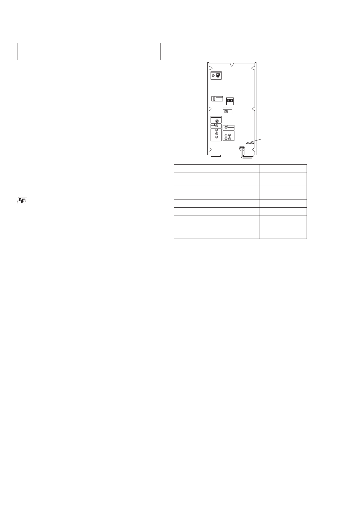
Region code of DVD VIDEOs you
can play back on this system
Your system has a region code printed
on the back of the unit and will only
play back DVD VIDEOs labeled with
identical region code.
DVD VIDEOs labeled will also be
played back on this system.
If you try to play back any other region
code DVD VIDEO, the message
“Playback prohibited by area limitations.”
will appear on the TV screen. Depending
on the DVD VIDEO, no region code
indication may be labeled even though
playing the DVD VIDEO is prohibited by
area restrictions.
Note on DualDiscs
A DualDisc is a two sided disc product
which mates DVD recorded material on
one side with digital audio material on
the other side. However, since the audio
material side does not conform to the
Compact Disc (CD) standard, playback
on this product is not guaranteed.
Notes on CD-R/-RW and
DVD-R/-RW/+R/+RW
In some cases, CD-Rs/-RWs and
DVD-Rs/-RWs/+Rs/+RWs cannot be
played back on this system due to the
recording quality or physical condition
of the disc, or the characteristics of
the recording device and authoring
soware. e disc will not be played
back if it has not been correctly
nalized. For more information, see
the operating instructions for the
recording device.
Note that some playback functions
may not work with some DVD+Rs/
+RWs, even if they have been correctly
nalized. In this case, view the disc by
normal playback.
A disc created in Packet Write format
cannot be played back.
Note on playback operations of
DVD VIDEOs and VIDEO CDs
Some playback operations of DVD
VIDEOs and VIDEO CDs may be
intentionally set by soware producers.
Since this system play back DVD
VIDEOs and VIDEO CDs according to
the disc contents the soware producers
designed, some playback features may
not be available. Also, refer to the
instructions supplied with the DVD
VIDEOs or VIDEO CDs.
Music discs encoded with
copyright protection technologies
is product is designed to play back
discs that conform to the Compact Disc
(CD) standard. Recently, various music
discs encoded with copyright protection
technologies are marketed by some
record companies. Please be aware that
among those discs, there are some that
do not conform to the CD standard and
may not be playable by this product.
Notes on Multi Session disc
If the rst session is recorded in
AUDIO CD or VIDEO CD format,
only the rst session will be played
back.
e system will recognize a Multi
Session disc as an AUDIO CD if there
is a session recorded in AUDIO CD
format on the disc. However, the
system will only play back the disc if
the rst session is recorded in AUDIO
CD format.
is system can play back Multi
Session discs when an MP3 audio
track, a JPEG image le or a DivX
video le is contained in the rst
session. Any subsequent MP3 audio
tracks, JPEG image les or DivX video
les recorded in later sessions can also
be played back.
With DATA CD or DATA DVD, the
system will only play back DivX video
les even if it contains MP3 audio
tracks or JPEG image les.

HCD-AZ33D
6
S-MASTER BOARD SERVICE POSITION
In checking the S-MASTER board, prepare jig (extension cable J-2501-077-A: 1.25 mm Pitch, 15 cores, Length 300 mm).
S-MASTER board
MAIN board
ADC board
connect jig (extension cable J-2501-077-A)
to the S-MASTER board (CN500) and MAIN board (CN102).
MAIN BOARD SERVICE POSITION
Note: Please reconnect cables after detaching the back panel section and CDM as shown in the figure.
VIDEO board
DMB17 board
MAIN board

HCD-AZ33D
7
HOW TO EJECT THE DISC WHEN POWER SWITCH TURNS OFF
Note: Please take out the DVD mechanism block from a set.
PRECAUTION WHEN REMOVING OPTICAL PICK-UP BLOCK
CAUTION
Lift up the FFC holder.
two claws
Be sure to execute a solder bridge as a measure against
static electricity when removing the OP block (DVBU101).
(Otherwise, the OP block will be destroyed.)
– DVD MECHANISM BLOCK Bottom view –
Please rotate the pully in the direction of the arrow after removing mechanism deck,
and eject the disc.
disc
– DVD MECHANISM BLOCK Bottom view –

HCD-AZ33D
8
SECTION 2
GENERAL This section is extracted
from instruction manual.
Guide to parts and controls
is manual mainly explains operations using the remote, but the same operations can
also be performed using the buttons on the unit having the same or similar names.
Unit
Remote control
* e DISC SKIP button is not available
for this model.
(on/standby)
Press to turn on the system.
Remote: TV 1) (on/standby)
Press to turn on the TV.
STANDBY indicator
Lights up when the system is turned o.
Display
(eject)
Press to eject the disc.
Disc slot
DVD
Touch to select the “DVD” function.
TUNER/BAND
Touch to select the “TUNER” function.
Touch to switch among FM and AM
band.
TAPE
Touch to select the “TAPE” function.
USB
Touch to select the “USB” function.
DMPORT
Touch to select the “DMPORT” function.
VIDEO/SAT
Touch to select the “VIDEO” or “SAT”
function.
Unit: (play)
Remote: 2) (play)
Touch or press to start playback.
(pause)
(stop)
Touch or press to stop or pause playback.
+/
Touch or press to select an album.
PRESET +/
Touch or press to select the preset station.
/ (go backward/
forward)
Touch or press to select a track, chapter
or video le.
Remote: TV CH +/ 1)
Press to change the TV channels.
VOLUME +/ 2)
Touch or press to adjust the volume.
Remote: TV VOL +/ 1)2)
Press to adjust the TV volume.
PUSH OPEN/CLOSE
Press to insert or eject a tape.
Tape deck
(USB) port
Connect an optional USB device (Digital
music player or USB storage media).
MIC 1/MIC 2 jacks
Connect to a microphone.
MIC LEVEL
Turn to adjust the microphone volume.
ECHO LEVEL
Turn to adjust the echo level.
PHONES jack
Connect the headphones.
Remote sensor
DIRECTION
Press to select the side of the tape to be
played back.
CD SYNC
START
Press to record on a tape.
Unit: DSGX
Press to reinforce the bass.
SOUND FIELD
Press to select the sound eld for the
surround sound.
Unit: PRESET EQ
Press to select the sound eect.
Unit: EQ EDIT
Press to select the frequency band.
PROGRESSIVE
Press to change the output video format
(Interlace or Progressive format).
DISPLAY
Press to display the disc information or
clock in the front panel display.
FUNCTION +/
Press to select the function.
PICTURE NAVI
Press to select the viewer format for
searching the chapters, titles and tracks.
Press to display the thumbnail pictures.
REPEAT/FM MODE
Press to listen to a disc, a single track or
le repeatedly.
Press to select FM reception mode
(monaural or stereo).
AUDIO
Press to display the current audio signal
on the TV screen.
SUBTITLE
Press to switch the language of the
subtitle (DVD VIDEO only).
D. TUNING
Press to switch to the direct tuning mode.
ANGLE
Press to change the angle (DVD VIDEO
with multi-angles only).
DVD/TUNER MENU
Press to display the menu items on the
TV screen.
Press to preset the radio station.
DISPLAY
Press to display the Control Menu on the
TV screen.
TUNING +/
Press to tune in the desired station.
SLOW
Press to watch the slow-motion play.
/ (rewind/fast forward)
Press to nd a point in a track, chapter or
video le.
TV1)
Press to operate the TV functions.
STEP
Press to play one frame at a time when
playback is paused.
ADVANCE
Press to advance the current scene during
playback.
REPLAY
Press to replay the previous scene during
playback.
RETURN
Press to return to the previous menu on
the TV screen.
///
Press to select the menu items.
ENTER
Press to enter the settings.
DVD TOP MENU
Press to display the DVD title on the TV
screen.
CLEAR
Press to delete a pre-programmed track
or le.
-/--1)
Press to enter a single digit or double
digit number.
Numeric buttons2)
Press to select a track, chapter or video
le.
Press to enter a password.
10/01)
Press to enter a double digit number.
KEY CONTROL
Press to change the key to suit your vocal
range.
SCORE
Press to select the diculty level for
scoring mode.
KARAOKE MODE
Press to select the Karaoke mode.
KARAOKE PON
Press to activate the “KARAOKE PON”
function.
TIME/TEXT
Press to change the information
appearing in the front panel display or
on-screen display.
SLEEP
Press to set the Sleep Timer.
TV INPUT1)
Press to switch the input sources.
TIMER MENU
Press to set the clock and the timers.
THEATRE SYNC
Press to activate the “THEATRE SYNC”
function.
1) is button is used to operate a Sony TV. For
details, see “Operating a Sony TV”.
2) e numeric button 5 , TV VOL + ,
VOLUME + and buttons on the
remote have a tactile dot. Use the tactile dot
as a reference when operating the system.
Display
Indicates the type of disc being played
back.
Indicates the selected play mode.
Indicates the le format.
Lights up when the title or chapter
number is displayed.
Lights up in “TUNER” function.
Displays the text information.
Lights up when the output video
signal is NTSC.
Lights up when the Karaoke Mode is
turned on.
Indicates the playback status of the
tape.
Indicates the playback direction of
the tape.
Lights up during recording.
Lights up when DSGX is turned on.
Indicates the current surround
format.
Lights up when the timer is set.
Lights up when the USB device is
recognized.
Lights up when “P AUTO” or “P
VIDEO” is selected.
Indicates the track information.
Indicates the selected function.
Indicates the playback status of the
disc or USB device.
Lights up when playing VIDEO CD
with PBC.

HCD-AZ33D
9
Rear panel DMPORT (DIGITAL MEDIA
PORT)
Connect the DIGITAL MEDIA PORT
adaptor (not supplied). You need to
connect the DIGITAL MEDIA PORT
adaptor to an optional audio device
(portable audio player, etc.).
Notes
Available DIGITAL MEDIA PORT
adaptors vary in each area.
Do not connect an adaptor other than
the DIGITAL MEDIA PORT adaptor.
Do not connect or disconnect the
DIGITAL MEDIA PORT adaptor
to/from the DMPORT while the system
is on.
When using a DIGITAL MEDIA PORT
adaptor (not supplied) that has video
output function, connect the adaptor
directly to the TV.
DVD/USB DIGITAL OUT jack
Connect the digital optical input jack
of an optional digital component
(such as amplier). You can enjoy
5.1 channel sound, if the connected
amplier equipped with Dolby Digital
or DTS decoder.
Notes
Sound is output only when the system
function is set to “DVD” or “USB.”
If you press AUDIO , SOUND FIELD
or the buttons related to Karaoke
Mode, or if you connect or disconnect
microphones or headphones, the sound
cuts o for a moment.
S VIDEO OUT jack
Connect the S Video input jack of
the TV. You can enjoy higher quality
video images when you select the
S VIDEO.
VIDEO OUT jack
Connect the video input jack of the
TV or projector.
COMPONENT VIDEO OUT jacks
Connect the component video input
jacks of the TV or projector. If your
TV accept progressive format signals,
you must use this connection and
press PROGRESSIVE on the unit
repeatedly to select “P AUTO” or “P
VIDEO.” You can enjoy higher quality
video images.
VIDEO/SAT OUT L/R jacks
Connect the audio input jacks of an
optional component (such as VCR or
MD deck).
VIDEO/SAT IN L/R jacks
Connect the audio output jacks of an
optional component (such as VCR or
satellite tuner).
SUBWOOFER OUT jack
Connect the audio input jack of an
optional subwoofer*.
* SA-GNV111D is recommended. In some
areas, the SA-GNV111D may not yet be
available.
Note
e eect may be limited or noise may
occur depending on the connected
subwoofer or the type of music being
played back.
Setting the clock
Use buttons on the remote to set the
clock.
1
Press /to turn on the
system.
2
Press TIMER MENU .
e hour indication ashes in the
display.
If “PLAY SET?” ashes in the display,
press or repeatedly to select
“CLOCK SET?,” then press ENTER
.
3
Press or repeatedly to set
the hour.
4
Press ENTER .
e minute indication ashes in the
display.
5
Press or repeatedly to set
the minutes.
6
Press ENTER .
e clock starts functioning.
Note
e clock settings are canceled when you
disconnect the power cord or if a power failure
occurs.
To display the clock when the system
is o
Press DISPLAY .
e clock is displayed for about 8
seconds.
D-LIGHT SYNC OUT jack
(Except for European and
Australian models)
Connect the D-LIGHT SYNC
controller (not supplied). You need
to connect the D-LIGHT SYNC
controller to the lighting device* (not
supplied). e lighting device will
react according to control signals
transmitted by the D-LIGHT SYNC
controller upon receiving music
source from the system. For details
on the use of D-LIGHT SYNC
controller and lighting device, refer to
the respective operating instructions
supplied with the respective device.
* Refer to the D-LIGHT SYNC
controller operating instruction for the
recommended lighting device.
Note
e lighting eect may be dierent
depending on the connected lighting
device or the type of music being played
back.

HCD-AZ33D
10
SECTION 3
DISASSEMBLY
• This set can be disassembled in the order shown below.
3-1. DISASSEMBLY FLOW
3-2. CASE
(Page 11)
3-3. S-MASTER BOARD
(Page 11) 3-5. SWITCHING
REGULATOR
(Page 12)
3-4. DC FAN (M701),
TUNER (FM/AM),
DMPORT BOARD
(Page 12)
3-6. DVD MECHANISM DECK
(CDM86-DVBU101)
(Page 13)
3-12. OPTICAL PICK-UP BLOCK
(KHM-313CAB)
(Page 16)
3-13. MOTOR (PULLEY) ASSY
(LOADING) (M001)
(Page 17)
3-14. HOLDER (BU) ASSY
(Page 17)
3-7. MAIN BOARD BLOCK
(Page 14)
3-11. TAPE MECH DECK
(CRP42603)
(Page 16)
3-10. FRONT PANEL BLOCK
(Page 15)
3-8. MAIN BOARD
(Page 14) 3-9. DMB17 BOARD
(Page 15)
3-15. LEVER (BU LOCK)
(Page 18)
3-16. CLOSE LEVER
(Page 18)
3-17. LEVER (DIR),
GEAR (IDL-B)
(Page 19) 3-18. CHASSIS (TOP)
(Page 19)
3-19. LEVER (LOADING-L/R)
(Page 20) 3-20. LEVER (DISC SENSOR)/
(DISC STOP)
(Page 21)
3-21. GEAR (IDL-C)
(Page 21)
SET

HCD-AZ33D
11
Note: Follow the disassembly procedure in the numerical order shown below.
3-2. CASE
case
seven screws
(BVTP3 ×8)
four screws
(case 3 TP2)
four screws
(case 3 TP2)
two claws
3-3. S-MASTER BOARD
two screws
(BVTP3 ×8)
two screws (BVTP3 ×10)
RT S-MASTER board
connector
(CN502)
RB radiation
sheet
connector
(CN503)
connector
(CN501)
flexible flat cable (13 core)
(CN500)
connector
(CN501)
screw
(BVTP3 ×8)
two screws
(BVTP3 ×8)
harness

HCD-AZ33D
12
3-4. DC FAN (M701), TUNER (FM/AM), DMPORT BOARD
3-5. SWITCHING REGULATOR
DC fan (M701)
tuner (FM/AM)
flexible flat cable (9 core)
(tuner/MAIN board: CN206)
flexible flat cable (9 core)
(DMPORT board: CN201/
MAIN board: CN209)
two screws
(BVTP3 ×8)
three screws
(BVTP3 ×8)
screw
(BVTP3 ×8)
screw (BVTP3 ×8)
three screws
(BVTP3 ×8)
screw (BVTP3 ×8)
(except AEP, AUS)
four screws (BVTP3 ×8)
RB two screws
(BVTP3 ×8)
two screws
(BVTP3 ×8)
two screws
(BVTT2.6 ×8)
two screws (BVTP3 ×10)
RT two screws
(BVTP3 ×8)
RG DMPORT board
connector
(CN203)
connector
(CN754)
RE bracket (DM port)
screw (BVTP3 ×8)
RH back panel (2DM)
shield (tuner)
three screws
(BVTP3 ×8)
two screws
(BVTP3 ×8)
screw
(BVTP3 ×8)
switching regulator
connector
(CN1)
connector
(CN2)
connector
(CN3)
connector
(CN4)
harness

HCD-AZ33D
13
3-6. DVD MECHANISM DECK (CDM86-DVBU101)
two screws
(BVTP3 ×8)
three screws
(BVTP3 ×8)
two claws
NOTE WHEN REMOVING DVD MECHANISM DECK (CDM86-DVBU101)
Some Screws on the CDM86-DVBU101 are hidden by the Front Panel,
and accordingly remove four Screws (BVTP3x8) on the Front Panel and
shift the Front Panel toward the front, and then remove the Screws on the CDM86-DVBU101.
CAUTION
wire (flat type) (7 core)
(CN001)
R wire (flat type) (24 core)
RB connector
Lift up the FFC holder.
two claws
Be sure to execute a solder bridge as a measure against
static electricity when removing the OP block (DVBU101).
(Otherwise, the OP block will be destroyed.)
RT DVD mechanism deck
(CDM86-DVBU101)

HCD-AZ33D
14
3-7. MAIN BOARD BLOCK
3-8. MAIN BOARD
two screws
(BVTP3 ×8)
two screws
(BVTP3 ×8)
bracket (top)
connector (CN3)
RG connector (CN302)
RH connector (CN951)
RI connector (CN952)
RK connector (NO956)
RL MAIN board block
connector (CN1)
flexible flat cable (13 core)
(CN102)
flexible flat cable (11 core)
(CN111)
flexible flat cable (7 core)
(CN304)
two screws
(BVTP3 ×8)
RT
RB screw
(BVTP3 ×8)
flexible flat cable (17 core)
(CN112)
RE connector (CN205)
flexible flat cable (5 core)
(CN111)
three screws (BVTP3 ×8)
connector (CN1203)
flexible flat cable (9 core)
(CN206)
flexible flat cable (19 core)
(CN202)
flexible flat cable (15 core)
(CN203)
flexible flat cable (9 core)
(CN209)
MAIN board
screw (BVTP3 ×8)
harness
connector
(CN401)

HCD-AZ33D
15
3-9. DMB17 BOARD
3-10. FRONT PANEL BLOCK
four screws
(BVTP3 ×8)
DMB17 board
connector
(CN401)
flexible flat cable (19 core)
(CN302)
flexible flat cable (15 core)
(CN106)
flexible flat cable (13 core)
(CN303)
flexible flat cable (5 core)
(CN111)
three screws
(BVTP3 ×8)
connector (CN503)
front panel block

HCD-AZ33D
16
3-11. TAPE MECH DECK (CRP42603)
3-12. OPTICAL PICK-UP BLOCK (KHM-313CAB)
flexible flat cable (5 core)
(CN002)
flexible flat cable (7 core)
(CN002)
two screws (BVTP2.6)
four screws (BVTP2.6)
two screws (BVTP2.6)
cover (TCM)
connector
Tape MECH Deck
(CRP42603)
Cut the binding band (taiton).
ferrite core
two insulator screws
two insulators two insulators
optical pick-up block
(KHM-313CAB)
two insulator screws

HCD-AZ33D
17
3-13. MOTOR (PULLEY) ASSY (LOADING) (M001)
3-14. HOLDER (BU) ASSY
Remove two solders.
two screws
(B 2.6 ×8)
MS-214 board
motor (pully) assy (loading)
(M001)
belt (MOT)
screw
(B 2.6 ×8)
lever (CL UP2)
holder (BU) assy
floating screw
(PTPWH M2.6)
floating screw
(PTPWH M2.6)
LHL support
two screws
(B 2 ×6)

HCD-AZ33D
18
3-15. LEVER (BU LOCK)
3-16. CLOSE LEVER
three hooks
lever (BU lock)
gear (BU lock)
gear (cap)
washer (3-1-0.4)
SPR-E lever close
shaft disc stop
close lever
claw

HCD-AZ33D
19
3-17. LEVER (DIR), GEAR (IDL-B)
3-18. CHASSIS (TOP)
pulley (gear)
nylon washer 1.7
claw
washer
Lever (DIR)
gear (IDL-A)
RB gear (IDL-B)
tension coil spring (DIR)
stoper
Loosen the screw.
Hold the release lever
and change the direction.
gear (cap)
screw
(B 2.6 ×8)
three screws
(B 2.6 ×8)
two screws
(B 2 ×10)
chassis (top)
lever (CL UP2)

HCD-AZ33D
20
3-19. LEVER (LOADING-L/R)
two hooks
two hooks
BOTTOM VIEW
lever (loading-L)
lever (loading-R)
SPT-T (loading-R) SPR-T (loading-L)
PRECAUTION DURING LEVER (LOADING R/L) INSTALLATION
lever (loading-R)
Align the horizontal position.
lever (loading-L)
Install the
both levers so that they move symmetrically.
Table of contents
Other Sony Stereo System manuals

Sony
Sony MHC-GNX660 User manual

Sony
Sony CMT-L1 - Micro Hi Fi Component System Manual

Sony
Sony MHC-EC69i/C2 User manual

Sony
Sony HCD-GT22 User manual

Sony
Sony LBT-XGR66 User manual

Sony
Sony HCD-GZR888D User manual

Sony
Sony ZS-XN30 - Cd Boombox User manual

Sony
Sony SHAKE-X70D User manual

Sony
Sony CMT-M90DVD - Micro Hi Fi Component System User manual

Sony
Sony HCD-RXD6AV User manual