– 2 –
TABLE OF CONTENTS
1. SERVICING NOTES .................................................. 3
2. GENERAL
Index to Parts and Controls ............................................... 5
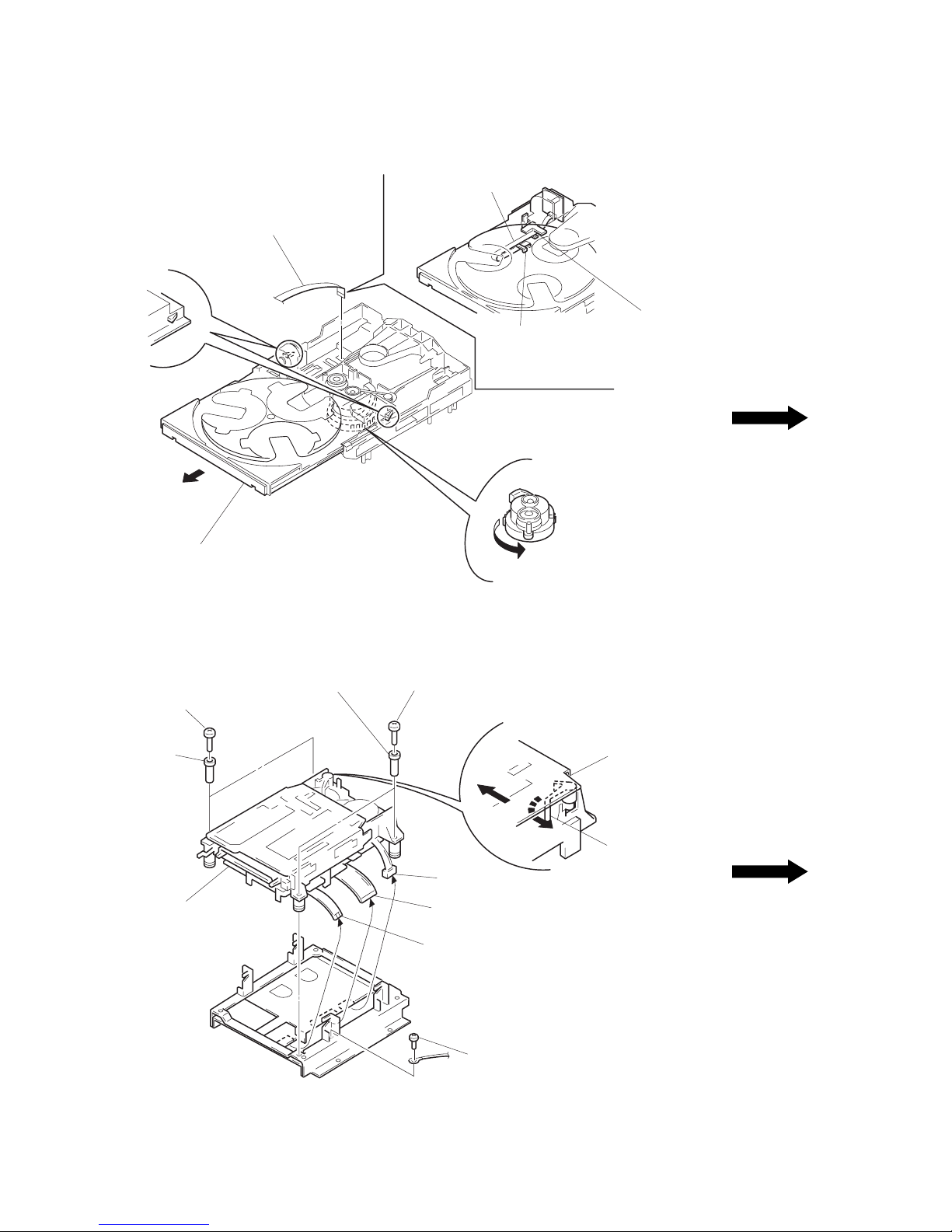
3. DISASSEMBLY............................................................ 7
4. TEST MODE ................................................................. 14
5. ELECTRICAL ADJUSTMENTS
MD Section........................................................................ 20
Tuner Section..................................................................... 25
CD Section......................................................................... 26
6. DIAGRAMS
6-1. Block Diagrams
CD Section......................................................................... 29
Tuner Section..................................................................... 31
MD Section........................................................................ 35
Main Section...................................................................... 39
6-2. Schematic Diagram – Tuner Section –
(AEP, G, UK model).......................................................... 44
6-3. Printed Wiring Board – Tuner Section –
(AEP, G, UK model).......................................................... 46
6-4. Printed Wiring Board – Tuner Section –
(EXCEPT AEP, G, UK model).......................................... 47
6-5. Schematic Diagram – Tuner Section –
(EXCEPT AEP, G, UK model).......................................... 48
6-6. Printed Wiring Board – CD Section – ............................... 50
6-7. Schematic Diagram – CD Section – .................................. 53
6-8. Printed Wiring Board –MD Section – ............................... 56
6-9. Schematic Diagram –MD Section – .................................. 59
6-10. Schematic Diagram – Digital Section – ............................ 63
6-11. Printed Wiring Boards – Digital Section – ........................ 67
6-12. Schematic Diagram – Relay Section – .............................. 70
6-13. Printed Wiring Board – Relay Section – ........................... 73
6-14. Printed Wiring Board – Main Section – ............................ 76
6-15. Schematic Diagram – Main Section – ............................... 79
6-16. Schematic Diagram – Power Section – ............................. 83
6-17. Printed Wiring Boards – Power Section – ......................... 87
6-18. Schematic Diagram – PowerAMP Section – .................... 92
6-19. Printed Wiring Boards – PowerAMP Section –................ 95
6-20. Schematic Diagram – Panel Section –............................... 99
6-21. Printed Wiring Boards – Panel Section – ........................ 103
6-22. IC Pin Function Description ............................................ 109
7. EXPLODEDVIEWS ................................................. 123
8. ELECTRICAL PARTS LIST .................................. 132
Tuner section
FM stereo, FM/AM superheterodyne tuner
FM tuner section
Tuning range
Tourist model: 76.0 – 108.0 MHz (50 kHz step)
Other models: 87.5 – 108.0 MHz (50 kHz step)
Aerial FM lead aerial
Aerial terminals 75 ohm unbalanced
Intermediate frequency 10.7 MHz
AM tuner section
Tuning range
German model:
AM: 522 – 1,611 kHz
(with the interval set at 9 kHz)
AEP, UK models:
MW: 522 – 1,611 kHz
(with the interval set at 9 kHz)
LW: 144 – 288 kHz
(with the interval set at 3 kHz)
Tourist model:
AM: 531 – 1,602 kHz
(with the interval set at 9 kHz)
530 –1,710 kHz
(with the interval set at 10 kHz)
Malaysia, Singapore,
Saudi Arabia,
Hong Kong models:
MW: 531 – 1,602 kHz
(with the interval set at 9 kHz)
530 – 1,710 kHz
(with the interval set at 10 kHz)
SW: 5.95 – 17.90 MHz
Aerial AM loop aerial
External aerial terminals
Intermediate frequency 450 kHz
General
Power requirements 220 – 230 V AC, 50/60 Hz
(AEP, German model)
110 – 120 V or 220 – 240 V AC,
50/60 Hz Adjustable with the
voltage selector (Other model)
Power consumption 85 watts (Tourist model)
130 watts (Other models)
Dimensions
Amplifier/Tuner/MD/CD section:
Approx. 280 ×240 ×360 mm
(11 1/8×9 1/2×14 1/4in) (w/h/d) incl.
projecting parts and
controls
(U.K., Hong Kong model)
Approx. 280 ×240 ×350 mm
(11 1/8×9 1/2×13 7/8in) (w/h/d) incl.
projecting parts and
controls (Other models)
Mass
Amplifier/Tuner/MD/CD section:
Approx. 9.4 kg
(20 lb 12 oz)
Supplied accessories: AM loop aerial (1)
Remote RM-S5MD (1)
Sony SUM-3 (NS)
batteries (2)
FM lead aerial (1)
Speaker cords (2)
Design and specifications are subject to change without notice.