SA-WCT290/WCT291
4
ADVANCE PREPARATION WHEN CONFIRMING OP-
ERATION
All the units included in the HT-CT290/HT-CT291 (SA-CT290/
CT291, SA-WCT290/WCT291, remote control) are required to
confirm the operation of SA-CT290/CT291. Check in advance that
you have all the units.
NOTE OF REPLACING THE IC8104 ON THE SUB MAIN
BOARD AND THE COMPLETE SUB MAIN BOARD
When IC8104 on the SUB MAIN board and the complete SUB
MAIN board are replaced, it is necessary to spread the compound
between the SUB MAIN board and the heat sink.
Spread the compound referring to the figure below.
– SUB MAIN Board (Component Side) –
compound
IC8104
NOTES ON THE WIRELESS CONNECTION (LINK) AFTER
REPAIRS ARE COMPLETE
When the parts below is replaced, the wireless connection (LINK)
of the Bar speaker and Subwoofer will be disconnected.
Before returning repaired products to the customer, follow the pro-
cedure below to LINK the Bar speaker and Subwoofer.
Also, if only the Bar speaker or Subwoofer is brought in for repair
and the parts below are replaced, be sure to inform the customer
when returning the repaired products that the customer must LINK
the Bar speaker and Subwoofer.
(Indicate that the LINK procedure is described in the operating
instructions)
Parts in which the LINK will be disconnected due to re-
placement:
• Complete SUB MAIN board
• BLUETOOTH MODULE (WB116A Y) (Ver C)
Activating wireless transmission between specific units
(Secure Link)
2Hold down CLEAR AUDIO+ for
5 seconds.
The USB and TV indicators flash
two times, then the MOVIE and
MUSIC indicators flash
alternately.
When the Bar Speaker is linked to
the subwoofer, the indicators stop
flashing and the power indicator on
the subwoofer lights up in orange.
If it failed, the indicators light up for
5 seconds. Try again the above
operation.
To deactivate this function, hold
down CLEAR AUDIO+ for
5seconds.
The USB indicator flashes twice.
You can specify the wireless connection
to link the Bar Speaker to the subwoofer
using the Secure Link function. This
function can help prevent interference if
you use multiple wireless products.
1Press LINK on the rear of the
subwoofer.
The power indicator on the
subwoofer flashes in orange.
THE ON/STANDBY INDICATOR FLASHES IN RED
If the power indicator flashes in red,
press Æon the subwoofer to turn
o the power and check whether
the ventilation opening of the
subwoofer is blocked or not.
BOND FIXATION OF ELECTRIC PARTS
When SWITCHING REGULATOR 3L411L board (US, CND) or
SWITCHING REGULATOR 3L411W board (Except US, CND,
E12) or SWITCHING REGULATOR 3L411W-1 board (E12) is
replaced, it is necessary to fix parts to the boards by using a speci-
fied bond without fail.
• Object boards
1. SWITCHING REGULATOR 3L411L board (US, CND)
2. SWITCHING REGULATOR 3L411W board (Except US,
CND, E12)
3. SWITCHING REGULATOR 3L411W-1 board (E12)
• Use bond
Part No. Description
7-600-020-70 ADHESIVE (SC608Z2) 180ML
• Parts position
1. SWITCHING REGULATOR 3L411L board
(US, CND) (page 4)
2. SWITCHING REGULATOR 3L411W board
(Except US, CND, E12) (page 5)
3. SWITCHING REGULATOR 3L411W-1 board
(E12) (page 5)
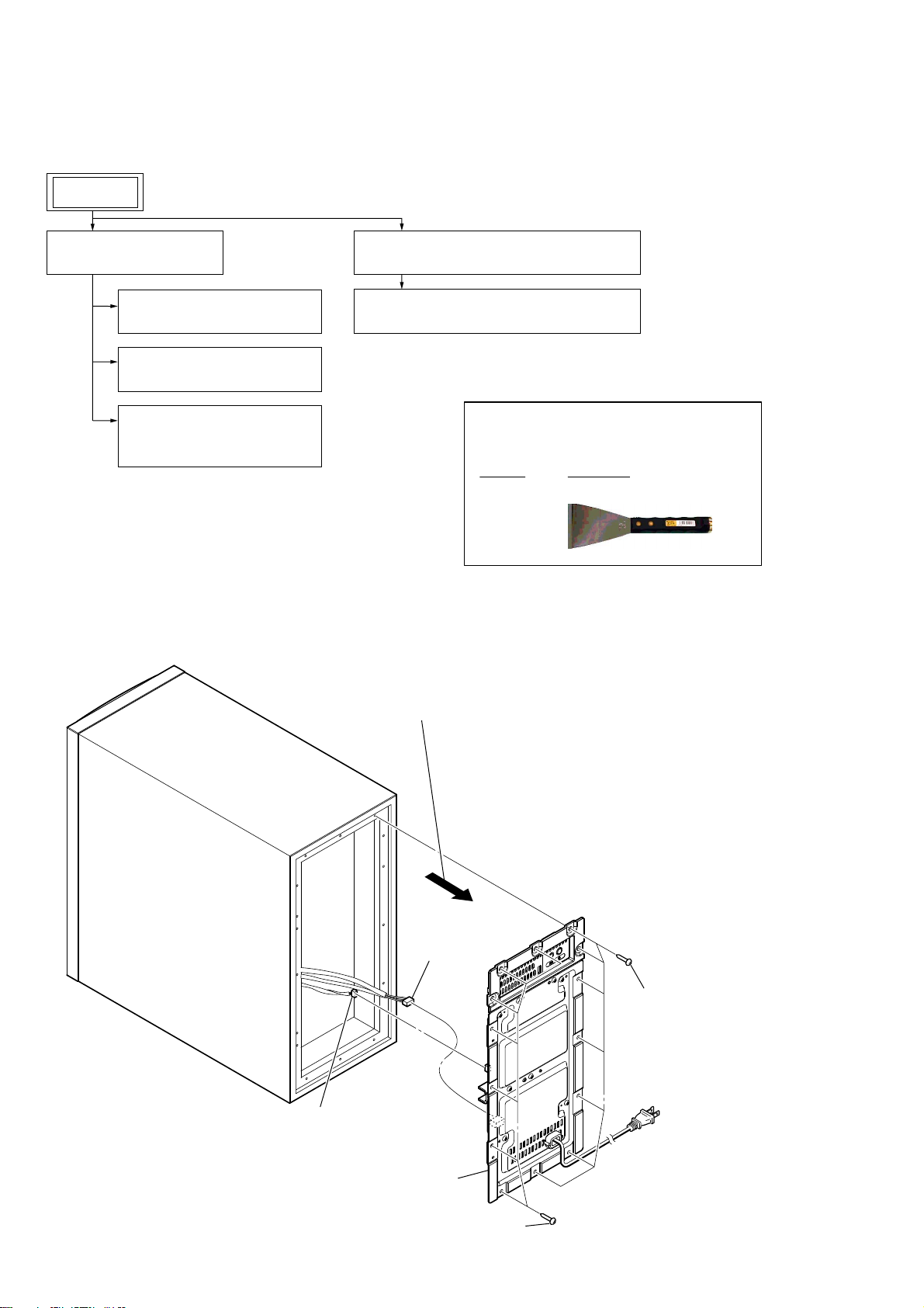
1. SWITCHING REGULATOR 3L411L board
(US, CND)
– SWITCHING REGULATOR 3L411L board
(US, CND) (Component Side) –
*The portion which applies bond: