manuals.online logo
Brands
  1. Home
  2. •
  3. Brands
  4. •
  5. Sony
  6. •
  7. TV
  8. •
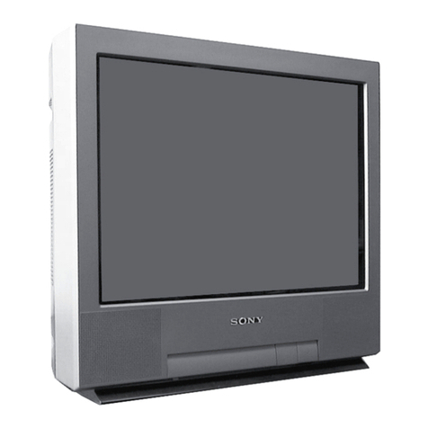
  9. Sony KV-27S26 - 27" Trinitron Color Television User manual

Sony KV-27S26 - 27" Trinitron Color Television User manual

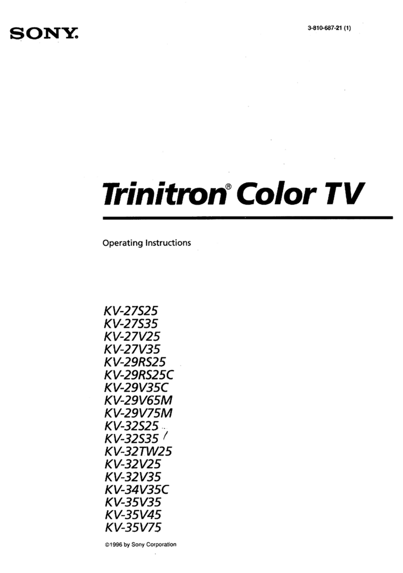
3-859-518-21
Trinitron Color TV
Operating Instructions
KV-27S26 KV-29RS26 KV-32S26 KV-34RS26C KV-35S26 KV-37RS26
KV-27S36 KV-29RS26C KV-32S36 KV-34V36C KV-35S36 KV-37V36M
KV-27V26 KV-29V36C KV-32TW26 KV-35V36
KV-27V36 KV-29V66M KV-32V26 KV-35V76
KV-29V76M KV-32V36
©1997 by Sony Corporation
Wt Table of Contents
Welcome! 1
Precautions 1
Using This Manual 1
Connecting two VCRs for tape editing
using MONITOROUT 8
Using the S-Link function 9
Connecting acamcorder 9
Installing the glass door 10
Adjusting the shelf 11
Basic Set Up
Inserting batteries 12
Using the remote control Select buttons 12
Adjusting sliders 12
On Line Help/Instructions 12
Using your New TV
Setting up the TV automatically 13
Watching the TV 14
Watching two programs at one
time —PIP 16
Adjusting your SET UP (menus)
Learning menu selection 18
Using the VIDEO menu 19
Using the AUDIOmenu 20
Using the TIMERmenu 21
Using the SET UP menu 22
Operating video equipment
Setting the manufacturer's code 24
Operating acable box or DBS receiver
Programming the remote 26
Troubleshooting 27
Specifications 28
Index 31
Owner's Record
The model and serial numbers are located at the rear
of the TV, below the Sony logo, on the sticker, and
also on the TV box (white label). Record these numbers
in the spaces provided below. Refer to them whenever
you call upon your Sony dealer regarding this product.
Model No. !®L
Serial No.
Connecting and Installing the TV
Connector Types 2
Making Connections 2
Connecting directly to cable
or an antenna 2
Cable or antenna ••3
Cable and antenna 3
Connecting acable box 3
Cable box and cable 3
Connecting-an antenna/cable TV system
with aVCR 4
Connecting to an S Video equipped
VCR 4
Connecting aVCRand TV with acable
box 5
Connecting to an SVideo equipped VCR
with acable box 5
Connecting aDBS receiver 6
Connecting aDBS receiver and aVCR .... 6
Connecting an audio system 7
Connecting an AV receiver 7
WMM IRemote Control
In the instructions that follow, we will refer
to the buttons on your remote control.
Keep this flap unfolded and look to this page
for reference.
SYSTEM OFF
(page 9and 15)
DISPLAY
SLEEP
JUMP
©TV/DBS
(page 20)
RESET
(page 19)
VOL +/-
CODE SET
(page 24)
ICD CD (
•o e e e
o"© ®
SONY
MUTING
TV (POWER)
TV (FUNCTION)
PIP (page 16)
TV/ VIDEO
ANT (page 3and 15)
0-9 buttons
ENTER
MTS (page 20)/GUIDE
Select buttons
(page 12 and 18)
MENU
CH +/-
Getting to know the buttons on the
remote control
Names of the buttons on the remote control are
presented in different colors to represent the
available functions.
Button color
Transparent .
.
.Press to select the componei
you want to control; e.g.
VTR (VCR), DBS (Direct
Broadcast Satellite)/CABLE
or TV.
Green Buttons relevant to power
operations, like turning the
TV, DBS (Direct Broadcast
Satellite)/CABLE, or VTR
(VCR) on or off.
Label color
White TV/VTR (VCR)/DBS (Direc
Broadcast Satellite)/CABLE
operation buttons.
Yellow PIP operation buttons.
Blue DBS (Direct Broadcast
Satellite) operation buttons.
Green S-Link operation buttons.
For adetailed explanation of most buttons, see
"Watching the TV" on page 14.
WARNING
To prevent fire or shock hazard, do not expose the TV
to rain or moisture.
CAUTION
RISK OF ELECTRIC SHOCK
DO NOT OPEN
ATTENTION
RISQUE DE CHOC ELECTRIQUE,
NE PAS OUVRIR
PRECAUCION
RIESGO DE CHOQUE ELECTRICO
NO ABRIR
CAUTION: TO REDUCE THE RISK OF ELECTRIC SHOCK,
DO NOT REMOVE COVER (OR BACK).
NO USER-SERVICEABLE PARTS INSIDE.
REFER SERVICING TO QUALIFIED SERVICE PERSONNEL.
AThis symbol is intended to alert the user to
the presence of uninsulated "dangerous
voltage" within the product's enclosure that
may be of sufficient magnitude to constitute
arisk of electric shock to persons.
This symbol is intended to alert the user to
the presence of important operating and
maintenance (servicing) instructions in the
literature accompanying the appliance.
CAUTION
When using TV games, computers, and similar products
with your TV, keep the brightness and contrast
functions at low settings. If afixed (non-moving)
pattern is left on the screen for long periods of time at
ahigh brightness or contrast setting, the image can be
permanently imprinted onto the screen. Continuously
watching the same program can cause the imprint of
station logos onto the TV screen. These types of
imprints are not covered by your warranty because
they are the result of misuse.
Note on Caption Vision
This television receiver provides display of television
closed captioning in accordance with §15.119 of the
FCC rules.
Note on cleaning the TV
Clean the TV with asoft dry cloth. Never use strong
solvents such as thinner or benzine, which might
damage the finish of the cabinet.
Note to CATV system installer
This reminder is provided to call the CATV system
installer's attention to Article 820-40 of the NEC that
provides guidelines for proper grounding and, in
particular, specifies that the cable ground shall be
connected to the grounding system of the building, as
close to the point of cable entry as practical.
Use of this television receiver for other than private
viewing of programs broadcast on UHF or VHF or
transmitted by cable companies for the use of the
general public may require authorization from the
broadcaster/cable company and/or program owner.
interference in aresidential installation. This
equipment generates, uses, and can radiate radio
frequency energy and, if not installed and used in
accordance with the instructions, may cause harmful
inteference with radio communications. However,
there is no guarantee that interference will not occur
in aparticular installation. If this equipment does
cause harmful interference to radio or television
reception, which can be determined by turning the
equipment off and on, the user is encouraged to try to
correct the interference by one or more of the
following measures:
•Reorient or relocate the receiving antennas.
•Increase the separation between the equipment and
receiver.
•Connect the equipment into an outlet on acircuit
different from that to which the receiver is
connected.
•Consult the dealer or an experienced radio/TV
technician for help.
You are cautioned that any changes or
modifications not expressly approved in this
manual could void your authority to operate this
equipment.
This document is for the remote control RM-Y136A/
Y137A.
MODELS: KV-27S26, 27S36, 27V26, 27V36, 29RS26,
29RS26C, 29V36C, 29V66M. 29V76M, 32S26,
32S36, 32TW26. 32V26, 32V36, 34RS26C.
34V36C, 35S26, 35S36, 35V36, 35V76, 37RS26,
37V36M
CAUTION
TO PREVENT ELECTRIC SHOCK, DO NOT USE THIS
POLARIZED AC PLUG WITH AN EXTENSION CORD,
RECEPTACLE, OR OTHER OUTLET UNLESS THE BLADES CAN
BE FULLY INSERTED TO PREVENT BLADE EXPOSURE.
NOTIFICATION
This equipment has been tested and found to comply
with the limits for aClass Bdigital device pursuant to
Part 15 of the FCC Rules. These limits are designed to
provide reasonable protection against harmful
WWelcome!
Thank you for purchasing the Sony Trinitron®
Color TV. This manual is written for the models
listed below. Before reading, check the model
number on the rear of your TV.
Model KV-27S26 is used for illustration
purposes. The screens displayed are for model
KV-35V36. Differences in operation features are
indicated in the text; for example, "KV-27S26
only".
KV-35S26
••••
.<?;> \.o- •
*•
BBS -o.
KV-27S26 •
-o-..' lilliiNl \a-
KV-27V26 ••
KV-29RS26 •mmV
KV-29V36C •••
§111 1
KV-29V76M • • •
KV-32S36 mm •
-
1
1
'•
KV-32V26
memne .
i
••
KV-34RS26C
.i1
o
mm*MPrecautions
Safety
•Operate the TV only on 120 VAC
(except KV-29RS26C, 29V36C, 34RS26C,
34V36C).
•Operate the TV only on 220 VAC
(KV-29RS26C, 29V36C, 34RS26C, 34V36C
only).
•The plug is designed, for safety purposes,
to fit in the wall outlet only one way. If
you are unable to insert the plug fully into
the outlet, contact your dealer
(except KV-29RS26C, 29V36C, 34RS26C,
34V36C).
•If any liquid or solid object should fall inside
the cabinet, unplug the TV immediately and
have it checked by qualified personnel
before operating it further.
•If you will not be using the TV for several
days, disconnect power by pulling the
plug itself. Never pull on the cord.
For details concerning safety precautions, see the
supplied leaflet "IMPORTANT SAFEGUARDS".
Installing
To prevent internal heat build-up, do not
block the ventilation openings.
Do not install the TV in ahot or humid
place, or in aplace subject to excessive
dust or mechanical vibration.
Ml Using This Manual
This manual is divided into four major
sections. We recommend that you carefully
review the contents of each section in the
order provided to ensure that you fully
understand the operation of your new TV.
1Connecting and Installing the TV.
This section will guide you through your
initial set up. It will show you how to
connect your new components, connect to
your antenna or cable, and connect any
accessories.
2Basic Set Up.
This section will teach you the basic skills
needed to operate your new TV. It will
show you how to operate special functions
of the remote control.
3Using your New TV.
This section will show you how to begin
using your new TV. It will show you how
to use the AUTO SET UP feature, and how
to use your remote control's features.
4Adjusting your Set Up (menus).
This section will teach you how to access
on-screen menus and adjust your TV's
settings.
Instructions in this manual are written for the remote
control. Similar controls may befound on the TV console.
flFMi Connecting and Installing the TV
Connector Types
You may find it necessary to use some of the
following connector types during set up.
Coaxial Cable
Standard TV Cable and Antenna connector
Plug Type $—*• Press onto connection
Screw-on Type
Tj3t& —Screw onto connection
SVideo Cable
High quality Video connector for enhanced
picture quality
=C(@Align guides and
press onto connection
Audio/Video Cable
Conventional Audio/Video cable
C
SQ^1—*• <!D Press onto connection
Yellow -Video
White -Audio (Left)
Red -Audio (Right)
S-Link Cable
Sony Link connector (only available on Sony
products) for simultaneous control of your
components
dEB™ *©Press onto connection
Making Connections
For best picture quality, acable TV system or
outdoor antenna is recommended.
Connecting directly to cable or an
antenna
The connection you choose will depend on
the cable found in your home. Newer homes
will be equipped with standard coaxial cable
(see A); older homes will probably have 300-
ohm twin lead cable (see B); still other homes
may contain both (see C).
VHF
and
UHF
75-ohm coaxial cable
(Rear of TVI
VHF/UHF
EAC-66 U/V mixer
(not supplied)
300-ohm twin lead cable
VHF only
or
VHF/UHF
or
Cable
75-ohm (Rear of TV)
coaxial cable VHF/UHF
=3lLI>»
Bvhp nniu 300-ohm twin (Rear of TV)
vnr- oniy |ead £ab|e VHF/UHF
or
UHF only
or
VHF/UHF Antenna connector
2
Cable or antenna
Most simple connection. Connection is made
directly from the cable or antenna to the TV.
Cable
(Rear of TV)
VHF/UHF
Cable and antenna
•KV-27S36, 27V36, 29V36C, 29V76M, 32S36, 32V36,
34V36C 35S36, 35V36, 35V76, 37V36M only
You may find it convenient to use the
following set up if your cable provider does
not feature local channels that you are able to
receive using an antenna.
(Rear of TV)
AUX
=QD—«G®
CATV cable
(No connection "TO
CONVERTER" in this case)
Antenna cable TO CONVERTER
VHF/UHF
Select Cable or ANT mode by pressing ANT on
the remote control.
Connecting acable box
Some pay cable TV systems use scrambled or
encoded signals that require acable box* to
view all channels.
Cable
(Rear of TV)
VHF/UHF
IN OUT
'Cable box
Note:
•If you will be controlling all channel
selection through your cable box you
should consider using the CHANNEL FIX
feature discussed on page 22.
Cable box and cable
•KV-27S36, 27V36, 29V36C, 29V76M, 32S36, 32V36,
34V36C, 35S36, 35V36, 35V76, 37V36M only
Some pay cable TV systems use scrambled or
encoded signals requiring acable box* only for
certain channels (e.g. HBO, SHOWTIME, etc.).
'Cable box
scrambled
channels
(Rear of TV)
AUX
=cx>—<S
TO CONVERTER
75-ohm coaxial
cable (not supplied) 1(signal)
<3D——<€8
CATV cable
(unscrambled channnels) VHF/UHF
For this set up, you can switch between scrambled
channels (through your cable box), and normal
(CATV) channels by pressing ANT on your
remote control.
•Your Sony remote control can be programmed
to operate your cable box (see page 26).
Notes:
•You cannot watch the signal through the
"AUX" input as awindow picture when
using Picture-in-Picture (PIP).
•If you are connecting acable box through
the"AUX" input and would like to switch
between the "AUX" and normal (CATV) input
you should consider using the CHANNEL FIX
feature discussed on page 22.
3
[Ml Connecting and Installing the TV (continued)
Connecting an antenna/cable TV
system with aVCR
1Attach the coaxial connector from your
cable or antenna to IN on your VCR.
2Using AUDIO/VIDEO connectors, connect
AUDIO and VIDEO OUT on your VCR to
AUDIO and VIDEO IN on your TV
(Yellow-VIDEO, White-AUDIO Left, Red-
AUDIO Right).*
3Using acoaxial connector, connect OUT on
your VCR to VHF/UHF on your TV.
Connecting to an SVideo equipped
VCR (for optimum picture quality)
1Attach the coaxial connector from your
cable or antenna to IN on your VCR.
2Using AUDIO connectors, connect AUDIO
OUT on your VCR to AUDIO IN on your TV
(White-AUDIO Left, Red-AUDIO Right).*
3Using acoaxial connector, connect OUT on
your VCR to VHF/UHF on your TV.
4Using an SVIDEO connector, connect
SVIDEO on your VCR to SVIDEO on
your TV.
*If you are connecting amonaural VCR, connect only
the single audio output to the left input on your TV.
Note on DVD Connection:
•For the best picture quality, connect the DVD player directly to the TV
Refer to your DVD manual for detailed connection information.
Disconnect all power sources before making any connections.
VCR must be connected and turned on to operate PIP
(KV-27S26, 27V26, 29RS26, 29RS26C 29V66M.32S2S.
32TW26. 32V26. 34RS2SC, 3SS26, 37RS2S only).
(Rear of TV)
Coaxial cable
AUDIO-R (red)
AUDIO-L (white)
VIDEO (yellow)
VMC-810S/820S (not supplied)
(Rear of TV)
Coaxial cable
YC-15V/30V
(not supplied)
1
1
RK-74A (not supplied)
SVIDEO
AUDIO-R (red)
AUDIO-L (white)
Connecting aVCR and TV with a
cable box
1Connect the single (input) jack of the
Splitter to your incoming cable connection,
and connect the other two (output) jacks
(using coaxial cable) to IN on your cable
box and VHF/UHF on your TV.
2Using acoaxial connector, connect OUT
on your cable box to IN on your VCR.
3Using AUDIO/VIDEO connectors,
connect AUDIO and VIDEO OUT on your
VCR to AUDIO and VIDEO IN on your
TV (Yellow-VIDEO, White-AUDIO Left,
Red-AUDIO Right).
ConnectingJto an SVideo equipped
VCR with acable box
(for optimum picture quality)
1-2 Perform as described above.
3Using AUDIO connectors, connect AUDIO
OUT on your VCR to AUDIO IN on your TV
(White-AUDIO Left, Red-AUDIO Right).
4Using an SVIDEO connector, connects VIDEO
on your VCR to SVIDEO on your TV.
Note:
•To view scrambled channels through your
cable box, select VIDEO 1by pressing TV/
VIDEO on the remote control.
Disconnect all power sources before making any connections.
VCR must be connected and turned on to operate PIP
(KV-27S26, 27V26, 29RS26. 29RS26C. 29V66M.32S26,
32TW26, 32V26, 34RS26C 3SS26, 37RS26 only).
(Rear of TV)
Coaxial cable
AUDIO-R (red)
(white)
(yellow)
Cable
Splitter
(not supplied)
OUT
4@l
Cable box
VMC-810S/820S (not supplied)
(Rear of TV)
1
Cable
Splitter
(not supplied)
SVIDEO
AUDIO-R (red)
AUDIO-L (white)
RK-74A (not supplied)
Cable box
Connecting and Installing the TV (continued)
Disconnect all power sources before making any connection
(Rear of TV)
Connecting aDBS (Direct Broadcast
Satellite) receiver
1Connect the cable from your satellite antenna
to your DBS receiver.
2Attach the coaxial connector from your cable or
antenna to VHF/UHF on your TV.
3Using AUDIO/VIDEO connectors, connect
AUDIO and VIDEO OUT on your DBS receiver
to AUDIO and VIDEO IN on your TV.
Connecting aDBS (Direct Broadcast
Satellite) receiver and aVCR
1Connect the cable from your satellite antenna
to your DBS receiver.
2Attach the-coaxial connector from your cable or
antenna to VHF/UHF-IN on your VCR.
3Using acoaxial connector, connect VHF/UHF-
OUT on your VCR to VHF/UHF on your TV.
4Using AUDIO/VIDEO connectors, connect
AUDIO and VIDEO OUT on your DBS receiver to
AUDIO and VIDEO IN on your VCR.
5Using AUDIO/VIDEO connectors, connect
AUDIO and VIDEO OUT on your VCR to
AUDIO and VIDEO IN on your TV.
For the highest picture quality, use SVIDEO
instead of the yellow AUDIO/VIDEO cable. See
your DBS manual for more information.
AUDIO-R (red)
AUDIO-L (white)
VIDEO (yellow)
VMC-810S/820S (not supplied)
-L (Rear of TV)
Note:
•To view input from the DBS or VCR, select VIDEO 1
by pressing TV/VIDEO on the remote control.
DBS receiver
VIDEO (yellow)
AUDIO-L (white)
AUDIO-R (red)
VMC-810S/820S (not supplied)
Connecting an audio system
For greater viewing pleasure, integrate your
home stereo into the system.
1Using AUDIO connectors, connect AUDIO
OUT on your TV to one of the unused Line
inputs (e.g. Tape-2, etc.) on your stereo (White-
AUDIO Left, Red-AUDIO Right).
2Set your stereo to the chosen Line input
and refer to page 20 of this manual for
additional audio setup instructions.
Connecting an AV receiver
•KV-27V36, 29V36C, 29V76M, 32V36, 34V36C,
35V36, 35V76, 37V36M only
For greater viewing pleasure, connect your
AV receiver.
1Using AUDIO/VIDEO connectors, connect
VIDEO 1IN on your TV to Monitor AUDIO
and VIDEO OUT on your AV receiver.
2Using AUDIO/VIDEO connectors, connect
TV OUT on your TV to TV AUDIO and
VIDEO IN on your AV receiver.
You may want to use CHANNEL FIX to fix your
TV's input to the AV receiver (VIDEO 1).
See CHANNEL FIX, page 22.
(Rear of TV) Disconnect all power sources before making any connections
RK-74A
(not supplied)
AUDIO-L (white)
AUDIO-R (red) ©Line
input
I 1 1 t t T^R t•
®
AUDIO-R (red)
AUDIO-L (white)
VIDEO (yellow)
VMC-810S/820S (not supplied)
(Rear of KV-27V36)
AV receiver
AV outputs
VIDEO (yellow)
AUDIO-L
AUDIO
yellow) -A A A
(white) -f-f U2
-R (red) —tr1
N'VMC-81
10S/820S (not supplied) AV inputs
[Ml Connecting and Installing the TV (continued)
Connecting two VCRs for tape
editing using MONITOR OUT
•KV-27V26, 27V36, 29V36C, 29V66M, 29V76M.
32V26. 32V36, 34V36C, 35V36. 35V76. 37V36M only
MONITOR OUT gives you the ability to use a
second VCR to record aprogram being played
by the primary VCR or to perform tape
editing and dubbing.
1Connect the VCR intended for playback
using the setup instructions on page 4of
this manual.
2Using AUDIO/VIDEO connectors,
connect AUDIO and VIDEO IN on your
VCR intended for recording to MONITOR
AUDIO and VIDEO OUT on your TV.
Disconnect all power sources before making any connection!
(Rear of TV)
VCR (for recording)
VIDEO (yellow)
AUDIO-f (white)
AUDIO-R (red)
VMC-810S/820S (not supplied) VMC-810S/820S (not supplied)
Notes:
•Do not change the input signal while
editing through MONITOR OUT.
•When connecting asingle VCR to the TV;
if VCR LINE OUT is connected to TV
VIDEO IN, do not connect the TV
MONITOR OUT jacks to the VCR LINE
INPUT (see right). Doing so will cause
program interference and other viewing
problems.
direction
8
Using the S-Link function Disconnect all power sources before making any connections
•KV-27V26, 27V36, 29V36C 29V66M, 29V76M, 32V26,
32V36, 34V36C 35V36, 35V76, 37V36M only
S-Link is aSony innovation designed to make
your Sony components work together. It allows
you to automatically switch the TV input mode
to video when you press PLAY on your Sony S-
Link VCR. It also allows you to turn the VCR
and TV off at the same time with the SYSTEM
OFF button.
1Connect your VCR using the setup
instructions on page 4of this manual.
2Using an S-Link connector, connect the
S-LINK jacks on your VCR and TV. Ensure
that both ends are seated firmly and that the
TV S-LINK connector is in the same row as
the AUDIO/VIDEO connectors.
Connecting acamcorder
•KV-27V26, 27V36, 29V36C, 29V66M, 29V76M, 32V26,
32V36, 34V36C, 35V36, 35V76, 37V36M only
This connection is convenient for viewing a
picture directly from your camcorder.
Using AUDIO/VIDEO connectors, connect
AUDIO and VIDEO OUT on your camcorder to
AUDIO and VIDEO IN on the front panel of your
TV (Yellow-VIDEO, White-AUDIO Left, Red-
AUDIO Right).
Note:
•If you are connecting amonoaural camcorder, connect only
the single audio output to the left input on your TV.
VCR (Rear of TV)
AUDIO-R (red)
AUDIO-L (white)
VIDEO (yellow)
Audio/Video Cable
(not supplied)
(Front of KV-32V36, 34V36C.
35V36, 35V76, 37V36M)
If you have an SVideo equipped camcorder,
you can use an SVideo connection for
optimum picture quality.
-U
SVDEO VIDEO 2INPUT
Jf VIDEO LflWHOWWDIO-R
@<§) <Q ®
AV output
VIDEO (yellow) —A AA-AUDIO-R (red)
\^ ^—AUDIO-L (white)
VMC-810S/820S
(not supplied)
Wi Connecting and Installing the TV (continued)
KV-32TW26 and KV-35V76 only
Follow these instructions to install the glass
door and adjust the shelf.
—Push here to close.
To open, push again.
Parts List
ABottom hinge tg3j 1
BTop hinge 1
CScrew 4x4 ©TO 4
DPlate pad 1
EPlate H=Z3 1
FMetal pin 4
Note:
•Confirm that all parts are included before
beginning assembly. If any parts are missing,
contact your dealer.
Installing the glass door
1Check that the projection of the screw
through the bottom hinge Adoes not
interfere with the proper installation of the
hinge to the glass door, and then insert the
hinge into the hole located at the bottom
right side of cabinet.
2Attach the top hinge Bto the right side of
the glass door; tighten the screws snugly,
but do not overtighten. Attach the plate
pad Dto the left side and push the plate E
over the plate pad.
10
3Push the top glass door hinge into the top
right bushing and gently slide the glass
door into the bottom hinge. Adjust the
glass door until level, and tighten the
hinge screws.
Adjusting the shelf
1Press the upper part of the temporary
shelf supports and remove the shelf.
2Insert the metal pin shelf supports (2 each
side).
3Insert the shelf, ensuring that the pin
supports are seated in the grooves on
bottom side of the shelf.
11
MBasic Set up
Inserting batteries
Insert two size AA (R6) batteries (supplied) by
matching the +and -on the batteries to the
diagram inside the battery compartment.
Notes:
•Remove the batteries to avoid damage
from possible battery leakage whenever
you anticipate that the remote control will
not be used for an extended period.
•Handle the remote control with care.
Avoid dropping it, getting it wet, or
placing it in direct sunlight, near aheater,
or where the humidity is high.
•Your remote control can be programmed to
operate most video equipment. See page 24.
Using the remote control
Select buttons On Line Help/Instructions
Several menu windows will provide prompts
and instructions to assist you in navigating
through the different functions. When
presented, use these to supplement the instructions
in this manual.
The supplied remote control has select
buttons which allow for movement of the on-
screen selector in four directions. Pressing on
the edge of the select buttons will cause the
selector to move in the selected direction.
Pressing the center of the select buttons "CD '
will activate the selected item.
Adjusting sliders
When menu items present aslider (wmm— or
—i—), use the select buttons (or )to adjust
the setting.
12
WUsing your New TV
Setting up the TV
automatically
The EASY SETUP GUIDE feature will allow you
to set the on-screen language and set all receivable
channels. The EASY SETUP GUIDE screen will
appear every time you turn on the TV until you
perform AUTO PROGRAM.
The EASY SETUP GUIDE feature does not apply
for installations that use acable box for all channel
selection.
To set up the TV manually, refer to "Using the
SET UP menu" on page 22.
Tips
•Perform this function during the day, with the antenna
and/or cable properly connected, to ensure that all available
channek will be broadcasting and receivable.
•After using EASY SETUP GUIDE you will still have the
option ofadjusting any of the system settings, like erasing
channek, through the SET UP menu (page 22).
•The TV must be set to TV input to execute AUTO
PROGRAM. Press ANTuntil the channel number appears.
•If your cable or antenna is connected to AUX, then
press ANT until "AUX" appears next to the channel
number. (KV-27S36, 27V36, 29V36C, 29V76M,
32S36, 32V36, 34V36C, 35S36, 35V36, 35V76,
37V36M only)
Using the buttons on the front of the TV:
SET UP TV/VIDEO -VOLUME .-CHANNEL .POWER
For KV-27V36, 29V36C, 29V76M, 32V36,
34V36C, 35V36, 35V76 and 37V36M, the control
buttons are located on the top of the TV.
1Press POWER to turn on the TV.
The EASY SETUP GUIDE screen appears.
ENGLISH :[CH +]
ESPANOL :[CH-]
AUTO SET UP :[VOH
DEMO :[TV/VIDEOl;
First please connect
the antenna.
Press [SET UP] to exit-
2(Except Canadian models)
Press CHANNEL +to select English
screens or CHANNEL -to select Spanish
screens.
3Press VOLUME- to continue or TV/VIDEO
for aDEMOof functions and menus.
AUTO PROGRAM
"AUTO PROGRAM" appears and the TV
starts scanning and presetting channels
automatically. When all the receivable channels
are stored, the lowest numbered channel is
displayed. If the TV receives cable TV channels,
CABLE is set ONautomatically.
To perform AUTO SET UP again
•Press SET UP.
•Press CHANNEL +or CHANNEL- to select a
language.
•Press Volume -to restore factory settings
("CONTINUE TO AUTO PROGRAM?"
will appear on the screen. Press CH+ to
execute or CH- to exit).
•Press SET UP to exit.
Note:
•When you perform AUTO PROGRAM,
your CHANNEL FIX, TIMER, and
CHANNEL BLOCK settings will be
erased.
13
MUsing your New TV (con tin ued)
Watching the TV
All of the TV features can be accessed via the
remote control. The following chart will
explain the function of the buttons found on
your remote control.
TV (FUNCTION) Activates the remote control for use with the TV.
TV POWER Turns the TV on and off. If "VIDEO" appears on the screen, press TV/VIDEO
or ANT so that achannel number appears.
®-® Use for direct channel selection. Press 0-9 to select achannel (for example,
to select channel 10, press 1and 0), the channel will change after 2seconds,
or you can press ENTER for immediate selection.
CH +/- —•Press to scan through the channels (+ up or -down).
VOL +/- Press to adjust the volume (+ up or -down).
JUMP Press to alternate or jump back and forth between two channels. You can only
jump between the last two channels that have been selected with the 0-9 keys.
MUTING Press to mute the sound ("MUTING" will appear on the screen). Press again
or press VOL +to restore sound.
FREEZE Press to freeze the window picture while in PIP mode. If you are not in PIP
mode, pressing FREEZE will cause the main picture to freeze into awindow
picture. Great for copying down phone numbers, addresses, recipes, etc.
REFER TO THE
ILLUSTRATION OF THE
REMOTE CONTROL ON THE
INSIDE FRONT COVER OF
THIS MANUAL AS YOU
REVIEW THIS CHART
14
SLEEP Press repeatedly until the TV displays the approximate time in minutes (30, 60,
or 90) that you want the TV to remain on before shutting off automatically.
Cancel by pressing until "SLEEP OFF" appears.
DISPLAY Press repeatedly to step through available displays:
Status
Channel number, current time, channel caption (if set), and MTS mode (if SAP is
selected) are displayed. SAP indication disappears after three seconds.
XDS
XDS (Extended Data Service) shows anetwork name, program name,
program type, program length, call letters, and time of the show if the
broadcaster offers this service.
Caption Vision
Caption Vision will be displayed on the screen if the broadcaster offers this
service, (see right)
To cancel the display, press DISPLAY repeatedly until "DISPLAY OFF"
aODears "DISPLAY OFF" riisannparc aftpr thrpp cornnHc
TV/VIDEO Press repeatedly to step through available video inputs:
TV, Video 1and Video 2(KV-27S26, 27S36, 29RS26, 29RS26C, 32S26
32S36, 32TW26, 34RS26C, 35S26, 35S36, 37RS26 only)
TV, Video 1Video 2and Video 3(KV-?7V?fi ?7V9fi pqv/^rp sovrkm
29V76M, 32V26, 32V36, 34V36C, 35V36, 35V76, 37V36M only)
ANT Press to change the VHF/UHF input to the AUX input (KV-27S36, 27V36,
29V36C, 29V76M, 32S36, 32V36, 34V36C, 35S36, 35V36, 35V76, 37V36M only)
Fof d&t3.iled connection information qpp T.ahlf* hny anri nahto" nr "P'sthlo anrl
antenna" on page 3.
SYSTEM OFF KV-27V26, 27V36, 29V36C, 29V66M, 29V76M, 32V26, 32V36, 34V36C,
35V36, 35V76, 37V36M only.
Press to turn off the TV and all other equipment connected with S-Link and
return the TV input to either antenna or AUX, whichever was last used.
MTS/GUIDE Press this button to cycle through the Multi-channel TV Sound (MTS) options, (page 20)
CAPTION
VISION
a
CAPTION VISION
TEXT 1
TEXT 2
TEXT 3
TEXT 4
3MENU
Use HE BP
Some programs are broadcast with Caption
Vision. To display Caption Vision, select CC1
,
CC2, CC3, CC4, TEXT1 ,TEXT2, TEXT3, or
TEXT4 from the menu, then press DISPLAY
until Caption Vision is displayed.
CC1 ,CC2, CC3, or CC4 shows you acaption,
that is, aprinted version of the dialogue or
sound effects of aprogram. (The mode should
be set to CC1 for most programs) TEXT1
,
TEXT2, TEXT3, or TEXT4 shows you text, that
is, information presented using either half or the
whole screen. It is not usually related to the
program.
Notes:
•Poor reception of TV programs can cause
errors in Caption Vision and XDS.
Captions may appear with awhite box or
other errors instead of intended text.
•XDS, Caption Vision, and the status display
cannot be used at the same time.
15
^MM#Using your New TV (continued)
Watching two programs at one time —PIP
The Picture-in-Picture (PIP) feature allows you
to view two channels simultaneously, one in
the full size "main" picture and one in asmaller
"window" picture. This means that two
separate tuners must be available to provide
the two signals.
Certain models (KV-27S26, 27V26, 29RS26,
29RS26C, 29V66M, 32S26, 32TW26, 34RS26C, 35S26,
37RS26 only) are equipped with asingle tuner.
This simply means that aVCR must be
connected and turned on for PIP to operate.
Tip
To ensure acorrectsingle tuner PIP connection (KV-
27S26, 27V26, 29RS26, 29RS26C, 29V66M, 32S26,
32TW26, 34RS26C, 35S26, 37RS26 only), make sure the
following list of simple connections is complete before
using PIP:
•A cable or antenna is connected to the VCR
•The VCR is connected to your TV
•The VCR is turned on
(for detailed connection information, see page 3-5)
Note:
•You must press TV (FUNCTION) before you
can control PIP with the yellow labeled buttons.
The sound of the main
picture is received.
^\
Main _
picture
REFER TO THE ILLUSTRATION OF
THE REMOTE CONTROL ON THE
INSIDE FRONT COVER OF THIS
MANUAL AS YOU REVIEW THIS
CHART
,Input-source mode
or TV channel for
the main picture
Input-source mode
or TV channel for
the window picture
Window
picture
pip
ePress once to display the window picture (1/9 size).
Press again to reduce the size of the window picture (1/1 6size).
Press athird time to remove the window picture.
TV/VIDEO
®Press repeatedly to step through available video inputs:
TV, Video 1, Video 2, and Video 3(KV-27V26, 27V36, 29V36C, 29V66M,
29V76M, 32V26, 32V36, 34V36C, 35V36, 35V76, 37V36M only)
If you use one of the connections from page 4, your PIP input source is the
VCR. If you use one of the connections from page 5, your PIP input source
is aVCR or cable box.
AUDIO
©Press to alternate sound between the main picture and the window picture.
AJ1will appear for afew seconds to indicate which picture is receiving
sound.
16

Other manuals for KV-27S26 - 27" Trinitron Color Television

2

This manual suits for next models

21

Other Sony TV manuals

Sony KV-BZ212 User manual

Sony

Sony KV-BZ212 User manual

Sony BRAVIA XR-85X9 K Series User manual

Sony

Sony BRAVIA XR-85X9 K Series User manual

Sony Bravia KE-48A9 User manual

Sony

Sony Bravia KE-48A9 User manual

Sony BRAVIA XBR-75X940D User manual

Sony

Sony BRAVIA XBR-75X940D User manual

Sony Bravia KDL-32E40 SERIES Service manual

Sony

Sony Bravia KDL-32E40 SERIES Service manual

Sony CTV-25R1 User manual

Sony

Sony CTV-25R1 User manual

Sony KDF50E2000 - 50" Rear Projection TV User manual

Sony

Sony KDF50E2000 - 50" Rear Projection TV User manual

Sony KD-55X85L User manual

Sony

Sony KD-55X85L User manual

Sony BRAVIA KDL-52Z5100 User manual

Sony

Sony BRAVIA KDL-52Z5100 User manual

Sony Trinitron KV-XG29N90 User manual

Sony

Sony Trinitron KV-XG29N90 User manual

Sony KV-32HS500 Instructions: TV stand  (primary... User manual

Sony

Sony KV-32HS500 Instructions: TV stand (primary... User manual

Sony Bravia KD-75XD9405 User manual

Sony

Sony Bravia KD-75XD9405 User manual

Sony BRAVIA KDL-70W857B User manual

Sony

Sony BRAVIA KDL-70W857B User manual

Sony KDL-46VL130 User manual

Sony

Sony KDL-46VL130 User manual

Sony KV-32V68 User manual

Sony

Sony KV-32V68 User manual

Sony BRAVIA XBR-55X930D User manual

Sony

Sony BRAVIA XBR-55X930D User manual

Sony KV-PF21DK7 User manual

Sony

Sony KV-PF21DK7 User manual

Sony Trinitron KV-EF34M80 User manual

Sony

Sony Trinitron KV-EF34M80 User manual

Sony BRAVIA KD-85X85K User manual

Sony

Sony BRAVIA KD-85X85K User manual

Sony KDL-22EX425 User manual

Sony

Sony KDL-22EX425 User manual

Sony TRINITRON KV-29FS150 User manual

Sony

Sony TRINITRON KV-29FS150 User manual

Sony BRAVIA XR-50X9xJ User manual

Sony

Sony BRAVIA XR-50X9xJ User manual

Sony Trinitron KV-EX29M93 User manual

Sony

Sony Trinitron KV-EX29M93 User manual

Sony Trinitron KV-BT212 User manual

Sony

Sony Trinitron KV-BT212 User manual

Popular TV manuals by other brands

RCA P60752 user guide

RCA

RCA P60752 user guide

Bush LE-32GKA instruction manual

Bush

Bush LE-32GKA instruction manual

JVC AV-21BS26 Service manual

JVC

JVC AV-21BS26 Service manual

Casio EV-660 Block Diagram

Casio

Casio EV-660 Block Diagram

Philips 46PFL4008S Specifications

Philips

Philips 46PFL4008S Specifications

Toshiba 28Z23G owner's manual

Toshiba

Toshiba 28Z23G owner's manual

Dynex DX-24E150A11 Guide d'installation rapide

Dynex

Dynex DX-24E150A11 Guide d'installation rapide

Sylvania SRT2127S owner's manual

Sylvania

Sylvania SRT2127S owner's manual

Philips 20HF7835/22 manual

Philips

Philips 20HF7835/22 manual

Samsung 9 Series user manual

Samsung

Samsung 9 Series user manual

Sharp 32U-S600 Service manual

Sharp

Sharp 32U-S600 Service manual

Toshiba 65X9763DAT operating instructions

Toshiba

Toshiba 65X9763DAT operating instructions

Technicolor - Thomson ICC19 Principles and Maintenance

Technicolor - Thomson

Technicolor - Thomson ICC19 Principles and Maintenance

LG 49UK7500PUA Easy setup guide

LG

LG 49UK7500PUA Easy setup guide

Samsung series 4 4000 user manual

Samsung

Samsung series 4 4000 user manual

Clarus TOP-131KTV user manual

Clarus

Clarus TOP-131KTV user manual

JVC AV-28BT8EEB instructions

JVC

JVC AV-28BT8EEB instructions

Sanyo CZP2530TXN Service manual

Sanyo

Sanyo CZP2530TXN Service manual

manuals.online logo
manuals.online logoBrands
  • About & Mission
  • Contact us
  • Privacy Policy
  • Terms and Conditions

Copyright 2025 Manuals.Online. All Rights Reserved.