— 3 —
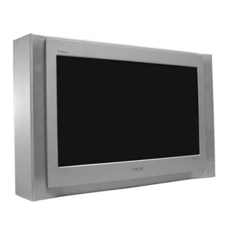
KD-34XBR2
TABLE OF CONTENTS
SpeciÞcations ................................................................................. 4
Warnings and Cautions .................................................................. 5
Safety Check-out ............................................................................ 6
Self-Diagnostic Function................................................................. 7
1. Disassembly
1-1. Rear Cover Removal.............................................................. 9
1-2. Chassis Assembly Removal................................................... 9
1-3. Picture Tube Removal .......................................................... 10
1-4. Service Position ................................................................... 11
2. Mechanical Pre-Adjustments
2-1. Ring Magnet Adjustments .................................................... 12
2-2. Neck Assembly Positioning .................................................. 12
3. Beam Landing and Raster Center Adjustments
3-1. Beam Landing Adjustment ................................................... 13
3-2. Raster Center Adjustment.................................................... 14
4. Picture Size and Geometry Adjustments
4-1. Full Mode Adjustment .......................................................... 15
4-2. Normal Mode Geometry Adjustment.................................... 20
4-3. Zoom Mode Geometry Adjustment ...................................... 20
4-4. Wide Zoom Mode Geometry Adjustment............................. 21
4-5. Twin Mode Geometry ConÞrmation...................................... 23
4-6. HD 1080i Mode Geometry Adjustment ................................ 23
5. Static Convergence Adjustments .................................................. 24
6. Dynamic Convergence Adjustments ............................................. 26
7. Picture Quality Adjustments
7-1. DTV Sub-Contrast Adjustment ............................................. 28
7-2. DTV Sub-Color and Sub-Hue Adjustment............................ 28
7-3. Analog Video Sub-Contrast Adjustment............................... 29
7-4. Analog Sub-Color and Sub-Hue Adjustment........................ 29
7-5. RF Sub-Contrast Adjustment ............................................... 30
7-6. Analog Video Sub-Color and Sub Hue Adjustment.............. 30
8. White Balance, Sub-Brightness and G2 Adjustments
8-1. White Balance Adjustment ................................................... 31
8-2. Sub-Brightness Adjustment.................................................. 32
8-3. G2 Adjustment ..................................................................... 32
SECTION TITLE PAGE
9. Safety Related Adjustments ........................................................... 33
10. Circuit Adjustments
10-1. Setting the Service Adjustment Mode................................. 34
10-2. Memory Write ConÞrmation Method ................................... 34
10-3. Remote Adjustment Buttons and Indicators........................ 34
10-4. Service Data Lists ............................................................... 35
10-5. Feature ID Map ................................................................... 67
11. Firmware Upgrade
11-1.Overview .............................................................................. 68
11-2.Transferring the New Firmware from
the Memory Stick to the Q-box............................................. 68
12. Diagrams
12-1.Circuit Boards Location ........................................................ 69
12-2.Printed Wiring Board & Schematic Diagram Information ..... 69
12-3.Block Diagram & Schematics
Block Diagram...................................................................... 70
A Board ................................................................................ 71
B Board ................................................................................ 77
C Board ................................................................................ 81
D Board ................................................................................ 83
F Board ................................................................................ 91
HA Board.............................................................................. 92
HB Board.............................................................................. 93
QI Board............................................................................... 94
QM Board............................................................................. 98
S Board .............................................................................. 109
U Board .............................................................................. 111
W Board ............................................................................. 113
12-4.Semiconductors ................................................................. 115
13. Exploded Views
13-1.Picture Tube ....................................................................... 117
13-2. Chassis.............................................................................. 118
13-3.Beznet ............................................................................... 119
14. Electrical Parts List ..................................................................... 120
SECTION TITLE PAGE
