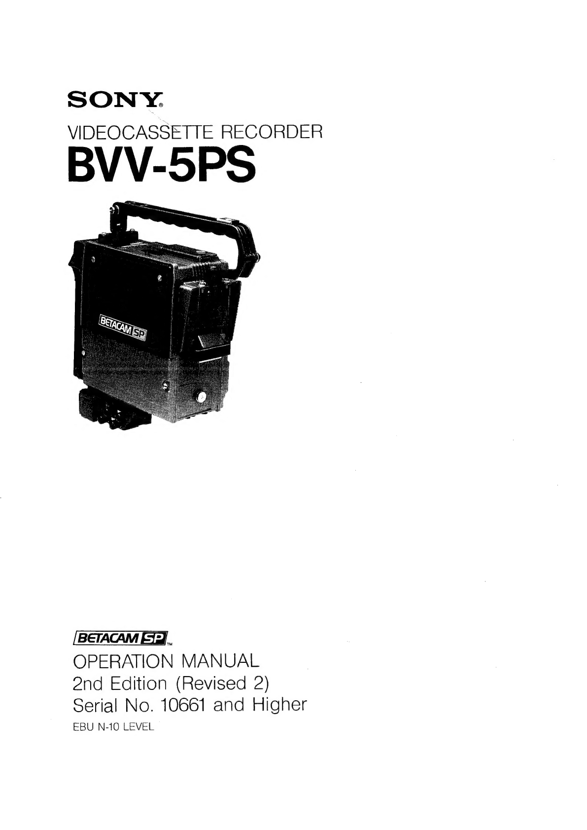
Outline
Location
and
Function
of
Parts
................ccccccceceeccene
eens
eeeeeeeesensaaseeeeneeenaeeneneeaenaeanaeas
4
(E)
Operation
Panel
oe...
eececeececsseeeceecseeeseeeceeeeeceeseaeeeeneeenseteceerseesetattesseereseeseeaeeenengen
4
(E)
GORMECIOR
PANels
i.
.iccsciecsck
ce
eacdecpeh
a
iste
la
ah
aad
was
cadetenveas
capveoeuaneg
piel
isceg
tees:
14
(E)
To
assemble
the
VTR
and
Camera
..................:cccccceesee
cess
seeeeeeeneeeeeneeeeenneeeeeeeeerennigs
16
(E)
To
change
the
Grip
Position...
ccc
eee
e
cee
ene
teeeeeeteese
te
taasennecaeeaeenanences
18
(E)
To
Attach
the
Shoulder
Strap
..........ccceeeeeccceseeseseceseseeseeeeeeeecneasseesseeenseseenneaeeeees
19
(E)
POWEr
SOULCOS
eels
cosesececsesenssecdcbicteacesvevads
sgh
dekisiisea
dace
endssdoceceeecegee
peente
Ai Ms
Salevia
ass
20
(E)
Rechargeable
battery
pack
NP-1,
NP-1A.........cccscsess
settee
ceeeseeteereeenrenaseaeeneee
20
(E)
Rechargeable
battery
pack
BP-90,
BP-90A...........:scusesseeseesressreesereneeeteeneateneees
21
(B)
AG.
POWSL
bs
cctes
sc
dicdeeicbvaec
ox
ugdengeascncestiuetiteascusnestesegueest
secebeaanedeteieeedseeseeehcornerse
retinas
22
(E)
COMMOCHION
ei5.c2tei
eet
de
weet
A
eas
cee
tteeci
ceea
ee
slg
sates
Bacon
aveneda
eas
anne
ue
cncseandaneeecnaben
23
(E)
Audio
recording
from
external
MiICrOPNONES
..........ccceceseesseeseeeteeettieetteeeeseeetens
23
(E)
Audio
recording
using
a
wireleSS
MICTOPNONG
..........:ccccceseeeetecetetnettteenenereraees
23
(E)
Audio
recording
from
external
EQUIPMENT
..........:cceeeseeseesereereettenetteeereeeetenteaeenes
24
(E)
VA-5P
VTR
composite/component
Adapt
..........cceccseesesereesecsteeetetereeeeetnneees
25
(E)
Time
Data
Setting...
cece
ccesseseeeeeeesseeeeeeeesecseseneeseaeeeeseeeeesnersenenanenneaeconsaas
26
(E)
Time
COdE
SEttiNg
..........cceccsccseeteesseeeeseecssseeseaasrssenscasseesteatesseesenseeeseetsentenesesnertes
26
(E)
User's
bit
Setting...
ee
esses
cceesssesenssensenscersusessassnsseseneresseccosssecescoeesseauensesoaes
27
(E)
Time COde
SlAaVE-LOCK.........ccccssceccserecesseeeeecesceeseseesaeeenssceseseaeeeesenaerensasensnasenaeentanee
29
(E)
Operation
Check
and
Adjustment
................cccceceseeseeceeeeeeeenereeeneesereeneereneeseaereees
32
(E)
Preparation
.....ccsccssccescesssscseseccesssnsssssssasseesteceeeseeseecesseeeassnsssseevacsserersaseassessaessaneas
32
(E)
Checking
the
VIR...
ecssessssssessssnsesssessceseseeeseeseeeessseesaeseesseseseetssonerserareoasonsanes
34
(E)
Checking
the
time
data
.........
cece
ccccessceseseeeseeeecssseeaseessereseeeaeeaetaeeeenesnenenen
38
(E)
Audio
recording
level
adjuStMent............cccceesecseseeeeeeeeeeseeneceeeteeereetnenaaeenaeerate
39
(E)
Alarm
sound
fJevel
adjuStment
..........c
ccc
ceeeeceeeesceeeeeeeesseeeseresesaeeesenaeeseseeaeeenenies
41
(E)
Operation
0...
eee
sssssssssessensscessssseesesesessenesessessenseessensassecerecetenessessnsseeenansanannananes
42
(E)
RECOPGING
.icscesecssescasseseeseseaeeoscneeceneostsinesdaensbnesey
saseusJanssusediengedesdnueestadannaneeysreeeestaecee
42
(E)
Playback
:.vtieiivisiewssiiiie
Weaveedcevieebhinnethcntiiows.
sedate
ee
eeniteiri
eevee
45
(E)
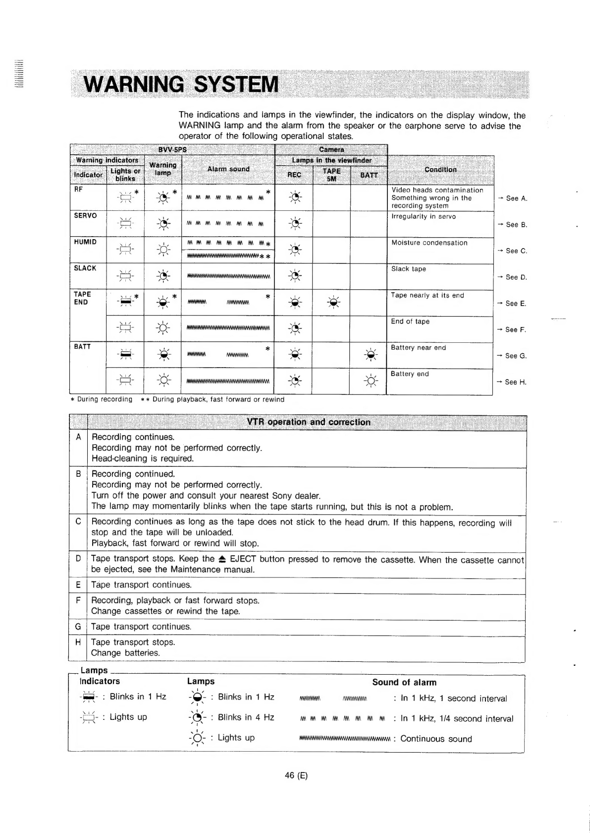
Warning
System...
cceccccccencereneeceneeneeeseeseeeaeeceenerssereceeseereseneeeesseenecieeseanegees
46
(E)
Notes
on
Operation
0...
ccececeeceeseceneeeeeee
cesses
ceeeeeeeseesssenesaussecceeenesseeseeenaeeaeegas
48
(E)
Specifications
«0.0...
csssssessssesessesesessstessensesesarenearesecesseseeeenestsesenseeeseaneaseeaneaeaes
49
(E)
The
operation
of
the
“Betacam”
system
is
described
in
the
operation
and
maintenance
manual
of
the
camera.
Please
refer
to
it
for
details.