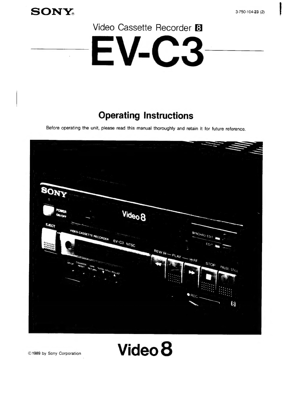
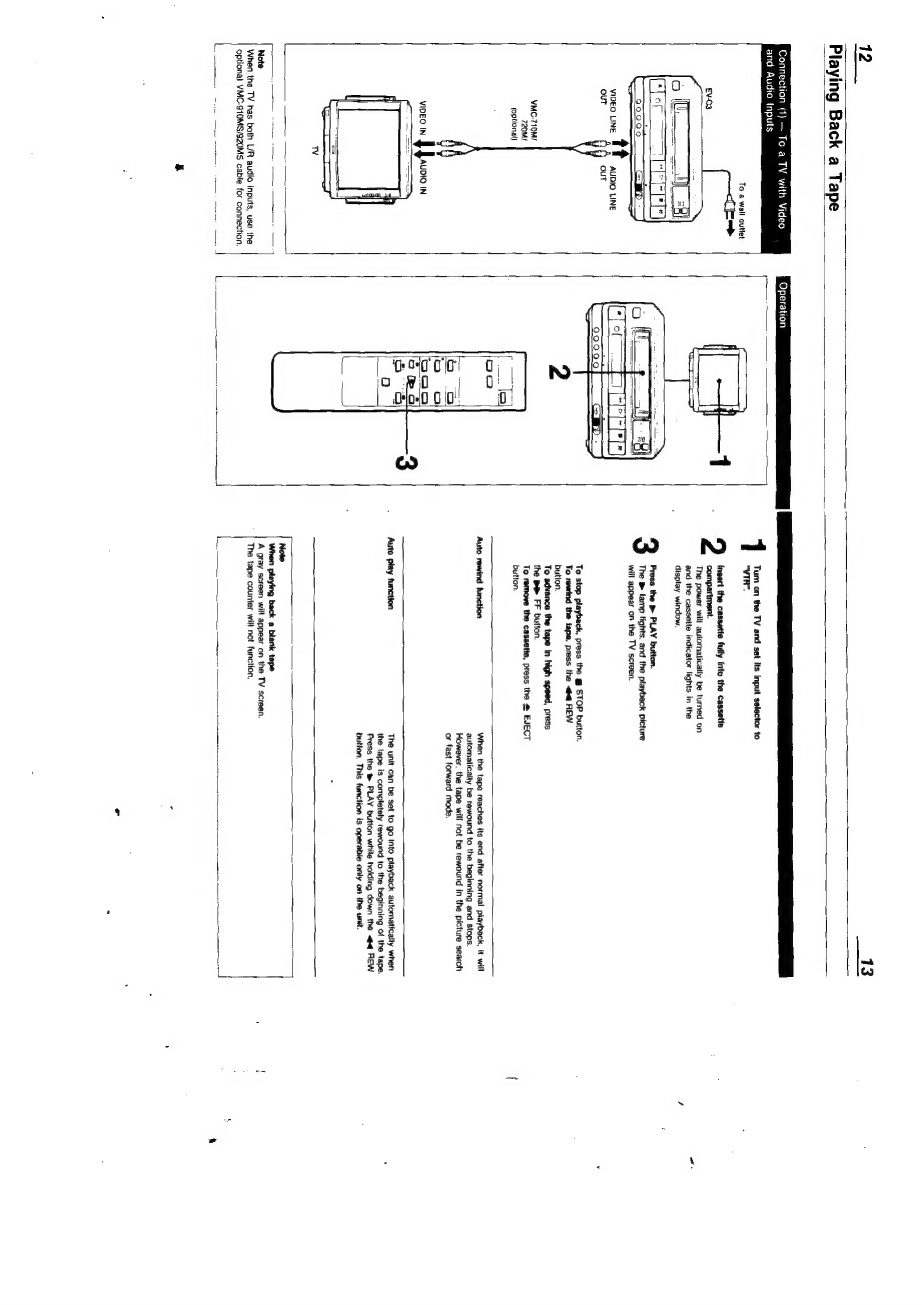
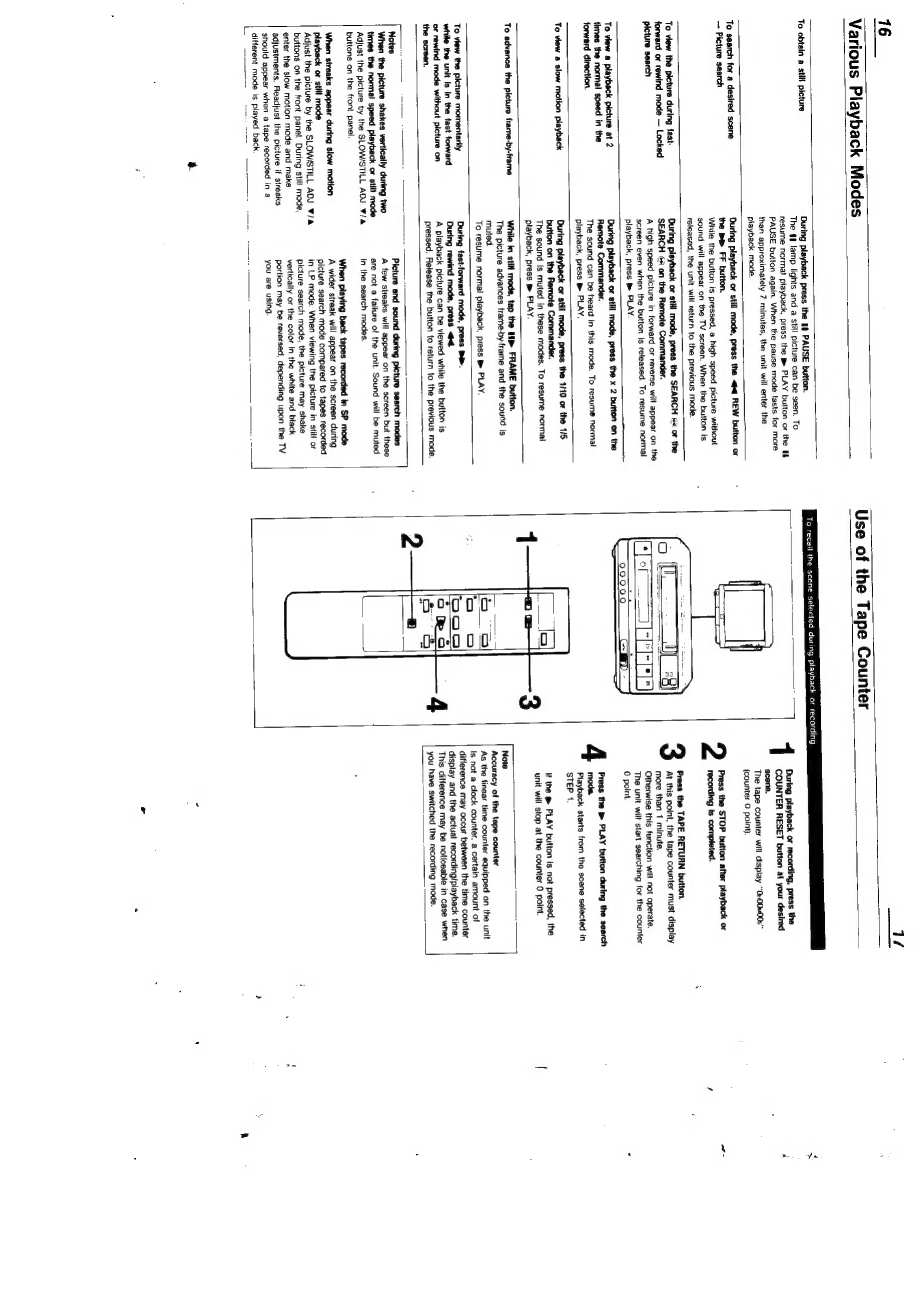
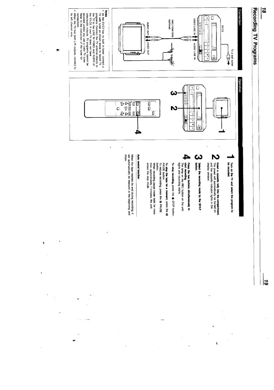
Sony EV-C3 User manual
Other Sony VCR System manuals

Sony
Sony DSR-40/40P User manual

Sony
Sony HANDYCAM HVR-M35U User manual

Sony
Sony SLV-N900 - 4 Head Hi-fi Stereo Vhs Video Cassette... User manual

Sony
Sony Walkman GV-9 User manual

Sony
Sony SLV-373UC - Video Cassette Recorder User manual

Sony
Sony SLV-SE70NP1, SLV-SE70NP2, SLV- User manual

Sony
Sony SRW-5000 User manual

Sony
Sony HDW-1800 User manual

Sony
Sony BVW-55 User manual

Sony
Sony ShowView SLV-SE230D User manual

Sony
Sony Video Walkman GV-F700 User manual

Sony
Sony SVO-5800 User manual

Sony
Sony SLV-798HF User manual

Sony
Sony SLV-662HF Operating Instructions (SLV-662HF / 679HF / 679HF PX... User manual

Sony
Sony Super Beta Hi-Fi SL-HF400 User manual

Sony
Sony HDW-500 User manual

Sony
Sony RDR VXD655 - DVDr/ VCR Combo User manual

Sony
Sony EZ77NZ User manual

Sony
Sony HVR-M10N User manual

Sony
Sony SLV-799HF - Video Cassette Recorder User manual