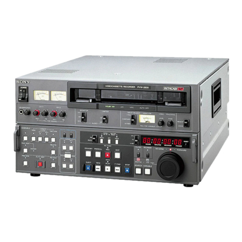
Sony BVW-55 User manual

VIDEOCASSETTE RECORDER
BVW-55
MAINTENANCE MANUAL Part 1
1st Edition
Serial No. 10001 and Higher

!WARNING
This manual is intended for qualified service personnel only.
To reduce the risk of electric shock, fire or injury, do not perform any servicing other than that
contained in the operating instructions unless you are qualified to do so. Refer all servicing to
qualified service personnel.
!WARNUNG
Die Anleitung ist nur für qualifiziertes Fachpersonal bestimmt.
Alle Wartungsarbeiten dürfen nur von qualifiziertem Fachpersonal ausgeführt werden. Um die
Gefahr eines elektrischen Schlages, Feuergefahr und Verletzungen zu vermeiden, sind bei
Wartungsarbeiten strikt die Angaben in der Anleitung zu befolgen.Andere als die angegeben
Wartungsarbeiten dürfen nur von Personen ausgeführt werden, die eine spezielle Befähigung
dazu besitzen.
!AVERTISSEMENT
Ce manual est destiné uniquement aux personnes compétentes en charge de l’entretien.Afin
de réduire les risques de décharge électrique, d’incendie ou de blessure n’effectuer que les
réparations indiquées dans le mode d’emploi à moins d’être qualifié pour en effectuer d’autres.
Pour toute réparation faire appel à une personne compétente uniquement.

CAUTION
Danger of explosion if battery is incorrectly
replaced.
Replace only with the same or equivalent type
recommended by the manufacturer.
Dispose of used batteries according to the
manufacturer’s instructions.
Vorsicht!
Explosionsgefahr bei unsachgemäßem
Austausch der Batterie.
Ersatz nur durch denselben oder einen vom
Hersteller empfohlenen ähnlichen Typ.
Entsorgung gebrauchter Batterien nach Angaben
des Herstellers.
ATTENTION
Il y a danger d’explosion s’il y a remplacement
incorrect de la batterie.
Remplacer uniquement avec une batterie du
même type ou d’un type équivalent recommandé
par le constructeur.
Mettre au rebut les batteries usagées
conformément aux instructions du fabricant.
ADVARSEL!
Lithiumbatteri-Eksplosionsfare ved fejlagtig
håndtering.
Udskiftning må kun ske med batteri
af samme fabrikat og type.
Levér det brugte batteri tilbage til leverandøren.
1 (P)
For the customers in the U.S.A. and Canada
RECYCLING NICKEL-CADMIUM
BATTERIES
Nickel Cadmium batteries are
recyclable. You can help preserve our
environment by returning your unwanted
batteries to your nearest point for
collection, recycling or proper disposal.
Note: In some areas the disposal of
nickel cadmium batteries in household or business trash
may be prohibited.
RBRC (Rechargeable Battery Recycling Corporation)
advises you about spent battery collection by the
following phone number.
Call toll free number: 1-800-822-8837
(United States and Canada only)
Caution: Do not handle damaged or leaking nickel-
cadmium batteries.
Voor de klanten in Nederland
Dit apparaat bevat een MnO2-Li batterij voor memory
back-up.
Raadpleeg uw leverancier over de verwijdering van de
batterij op het moment dat u het apparaat bij einde
levensduur afdankt.
Gooi de batterij niet weg. maar lever hem in als KCA.
Bij dit produkt zijn batterijen geleverd.
Wanneer deze leeg zijn, moet u ze niet
weggooien maar inleveren als KCA.
BVW-55


1
BVW-55
Table of Contents
Manual Structure
Purpose of this manual .............................................................................................. 5
Contents ..................................................................................................................... 5
Related manuals......................................................................................................... 6
1. Service Overview
1-1. Power Supply ..............................................................................................1-1
1-2. Matching Connectors/Cables ......................................................................1-2
1-3. Connector Input/Output signals ..................................................................1-3
1-4. Location of Main Parts and Circuit Functions ............................................1-6
1-4-1. Function and Location of Printed Circuit Boards ......................1-6
1-4-2. Main Mechanical Part Locations ...............................................1-8
1-4-3. Function and Location of Sensors ............................................1-10
1-5. System of Cassette ....................................................................................1-12
1-6. Removing/Reinstalling the Cabinet ..........................................................1-13
1-6-1. Battery Sub Panel .....................................................................1-13
1-6-2. Upper Frame.............................................................................1-14
1-6-3. Connector Panel .......................................................................1-16
1-6-4. Bottom Plate .............................................................................1-17
1-7. Removing/Reinstalling the Cassette Compartment ..................................1-18
1-8. Disconnecting/Reconnecting the Printed Circuit Boards..........................1-19
1-8-1. Plug-in Board ...........................................................................1-19
1-8-2. DM-121 Board .........................................................................1-21
1-9. Settings for Internal Switches/Slit Lands ..................................................1-22
1-10. Description on Internal Indicators.............................................................1-32
1-11. How to Take Out the Cassette When the Tape is Slacked ........................1-36
1-12. Cleaning Clogged Video Heads ................................................................1-37
1-13. Power Protection .......................................................................................1-37
1-13-1. Overcurrent Protection .............................................................1-37
1-13-2. Information on IC Link ............................................................1-37
1-14. Battery for Memory Backup .....................................................................1-38
1-15. Fixtures and Adjustment Equipment List .................................................1-39
1-15-1. Fixtures.....................................................................................1-39
1-15-2. Equipment for Adjustment .......................................................1-41
1-16. Settings for External Editors .....................................................................1-42
1-16-1. Time Code Settings for Recorder.............................................1-42
1-16-2. VTR Constant Settings for External Editors ............................1-42
1-16-3. System Phase Adjustment ........................................................1-43
1-16-4. Setup Menu Setting of ITEM-701............................................1-43
1-17. Setup Menu ...............................................................................................1-44
1-17-1. Menu Operation .......................................................................1-44
1-17-2. F-Series items ...........................................................................1-45
1-18. Threading End and Unthreading End States .............................................1-46
2BVW-55
2. Error Message
2-1. Overview of Error Message ........................................................................2-1
2-2. Details of Error Messages ...........................................................................2-3
3. Maintenance Mode
3-1. Overview of Maintenance Mode.................................................................3-1
3-2. TAPE Maintenance Mode (M0)..................................................................3-6
3-2-1. Overviews ..................................................................................3-6
3-2-2. SERVO CHECK Mode (C0) ...................................................3-10
3-2-3. AUDIO/VIDEO CHECK Mode (C2) ......................................3-22
3-3. Error Logger Display Mode (M2).............................................................3-24
3-3-1. Outline......................................................................................3-24
3-3-2. Display Mode ...........................................................................3-25
3-3-3. Setting Mode ............................................................................3-27
3-4. OTHERS CHECK Mode (M3) .................................................................3-29
3-4-1. Outline......................................................................................3-29
3-4-2. ROM VERSION Display Menu (M30) ...................................3-30
3-4-3. SERIAL NUMBER Display Menu (M31)...............................3-30
3-4-4. HOUR METER RESET Menu (M36) .....................................3-31
3-5. Setup Maintenance Mode (M4) ................................................................3-32
3-5-1. Outline......................................................................................3-32
3-5-2. EXTENDED MENU Display Selection Menu (M40) .............3-32
3-5-3. RESET ALL SETUP Executing Menu (M49) .........................3-33
4. Periodic Maintenance and Inspection
4-1. Periodic Maintenance..................................................................................4-1
4-1-1. Index...........................................................................................4-1
4-1-2. Periodic Replacement and Check Item Table ............................4-2
4-1-3. Hours Meter ...............................................................................4-3
4-2. Cleaning ......................................................................................................4-4
4-2-1. Using Cleaning Tape ..................................................................4-4
4-2-2. General Information for the Use of Cleaning Cloth...................4-4
4-2-3. Cleaning of Video Heads and
Tape Running Surface of Upper Drum ......................................4-5
4-2-4. Cleaning of Lead Surface and
Tape Running Surface of Lower Drum......................................4-6
4-2-5. Stationary Heads and Tape Cleaner Cleaning............................4-7
4-2-6. Tape Running System Cleaning.................................................4-8
4-3. Cares After Outdoor Use.............................................................................4-9

3
BVW-55
5. Spare Parts
5-1. Notes on Repair Parts..................................................................................5-1
5-2. Exploded Views ..........................................................................................5-2
5-3. Plug-in Boards.............................................................................................5-3
5-4. Supplied Accessories List ...........................................................................5-4
5-5. Fixtures List ................................................................................................5-4
6. Circuit Description and Overall Block Diagram
Appendix A Setting Check Sheet


5
BVW-55
Purpose of this manual This manual is the maintenance manual part1 of videocassette recorder BVW-55.
This manual is intended for use by trained system and service engineers, and
provides the setting and maintenance information that is necessary at the time of
primary service.
Contents This manual is organized by following sections.
Section 1 Service Overview
Explains the fundamental information that is required to service, (removal of cabinet
and cassette compartment, the functions of printed circuit board, the locations of
main part, fixture and measuring equipment information, notes, etc.) and the mea-
sures against trouble.
Section 2 Error Message
Explains the error messages.
Section 3 Maintenance Mode
Explains each menu of the maintenance mode.
Section 4 Periodic Maintenance and Inspection
Explains the recommended periodic maintenance, and the cleaning procedure.
Section 5 Spare Parts
Describes the spare parts list and the exploded view for the service parts of this unit,
and the supplied accessories list.
Section 6 Overall Block Diagram and Circuit Description
Describes the overall block diagram and the circuit description.
Appendix A Setting Check Sheet
The sheet is used for checking the setup conditions such as switch, setup menu under
the application.
Manual Structure

6BVW-55
Related manuals Besides this “maintenance manual part 1”, the following manuals are available for
videocassette recorder BVW-55.
• Operation Manual (Supplied with the BVW-55.)
This manual is necessary for application and operation of the BVW-55.
• Maintenance Manual Part 2 (available on request )
This manual describes the information that premises the parts level service
(adjustments, board layouts, schematic diagrams, detailed parts list, etc.) for this
unit.
If this manual is required, please contact your local Sony Sales Office/Service
Center.
• Protocol Manual of Remote (9-pin) Connector (soon-to-be-available)
This manual explains the protocol for controlling the VTR via the RS-422A (9-pin
serial remote).
If this manual is required, please contact your local Sony Sales Office/Service
Center.
• BKNW-225 Maintenance Manual (Supplied with the BKNW-225)
This manual describes the spare parts list and the exploded view for the service
parts of the docking kit BKNW-225, that is used when the two BVWs are coupled.

1-1
BVW-55
DC IN
AC adaptor
AC-DN2A
AC adaptor
AC-550
Lithium-ion battery
BP-L90/L60
Ni-cd battery
BP-90A
+
Battery adaptor
DC-L90
Ni-cd battery
BP-90A
+
Battery adaptor
DC-210
DC OUT
AC adaptor
AC-DN2
BVW-55
Rear View
Battery terminal
(DC cable)
Section 1
Service Overview
1-1. Power Supply
The unit works either on AC current (using the AC adaptor) or battery. When repairing or checking the
unit, AC-operation is recommended.
Power Voltage: DC 11 to 17 V
Power Consumption : 65 W
m
.The AC adaptor AC-DN1 cannot be used to derive power.
.The AC adaptor AC-DN2A can supply power to two VTRs simultaneously. The AC-DN2 with serial
No.11001 or higher can supply, too. If the above adaptor is used, power on the VTRs and load cassettes
in turn allowing for an inrush current.
.While the unit is battery-operated, the remaining battery capacity is displayed on the sub LCD. When
the battery is nearly dead, the WARNING indicator on the side of the LCD monitor will blink. For
details, refer to the operation manual supplied with the unit.
Connection example (when operating two VTRs)

1-2 BVW-55
1-2. Matching Connectors/Cables
Connection made with the connector panels during installation or service, should be made with the
connectors or complete cable assemblies specified in the following list, or equivalent parts.
Panel indication Matching connector (Sony P/N) Matching cable (Sony P/N)
VIDEO REF IN Plug, BNC 75 Z(1-569-370-12) RG-59B/U cable
VIDEO INPUT
VIDEO OUTPUT
TC IN
TC OUT
SDI IN Plug, BNC 75 Z(1-569-370-12) BNC coaxial cable
SDI OUT (1-783-090-11:supplied with BKNW-225) or
BELDEN 8281 cable (Maximum cable length: 200m)
AUDIO INPUT XLR 3P, MALE (1-508-084-00) –––––––
AUDIO OUTPUT XLR 3P, FEMALE (1-508-083-00) –––––––
MONITOR OUTPUT
DC IN XLR 4P, FEMALE (1-508-362-00) DC power cord
(1-551-577-00:supplied with AC-550/550CE)
DC OUT Plug 4P MALE (1-566-425-11) –––––––
REMOTE Plug 9P MALE (1-560-651-00) 9P remote control cable
Shell, Junction 9P (1-561-749-00) (1-783-089-11:supplied with BKNW-225) or
RCC-5G(5 m)/10G(10 m)/30G(30 m)
AUX Plug 6P MALE (1-560-078-00) –––––––
HEADPHONES JM-60 stereo phone plug –––––––
(commercially available)
1-2. Matching Connectors/Cables

1-3
BVW-55
1-3. Connector Input/Output signals
Communications connectors
6REMOTE D-SUB 9P connector x1 (RS-422A interface)
Remote control
![ AUX 6-pin connector x1
Input connectors
1AUDIO INPUT CH-1/CH-2 XLR 3-pin x2
Analog audio 2 channels
_60 dBu, 0 dBu, +4 dBu selectable, high impedance, balanced
2VIDEO REF.IN BNC x2 (In loop through connection, with 75 Ztermination switch)
External reference video signal (Black burst or composite sync)
40 IRE/0.3 Vp-p, 75 Z, negative sync
3VIDEO INPUT BNC x2 (In loop through connection, with 75 Ztermination switch)
Analog composite video 1.0 Vp-p, 75 Z, negative sync
!- SDI IN BNC x1
Component digital (270 Mbit/s) SMPTE 259M/ITU-R BT.656
8TC IN BNC x1
Time code 0.5 to 18.0 Vp-p, 10 kZ, unbalanced
!\ DC IN XLR 4-pin x1
DC +11 to 17 V
BATTERY IN 5-pin terminal x1
(on battery sub panel) Lithium-ion battery interface
1-3. Connector Input/Output signals
REMOTE
TC IN
TC OUTSDI OUT
SDI IN DC OUT
DC-IN
AUX
12
VIDEOAUDIO INPUT
REF.
IN
AUDIO OUTPUT
ONOFF
75Z
ONOFF
CH-1
1/3
+48V +4dBu_60 0
ONOFF
CH-2
+48V +4dBu_60 0
INPUT OUTPUT
ON
1
2(SUPER)
OFF
75Z
2/4
MONITOR OUTPUT
R L
1
9 !/ != ![ !\!]!-
2 3 4 6 875
〈 Connector panel 〉

1-4 BVW-55
Output connectors
4VIDEO OUTPUT 1 BNC x1
Analog composite video 1.0 Vp-p, 75 Z, negative sync
5VIDEO OUTPUT 2 BNC x1 (Character superimpose enabled)
Analog composite video 1.0 Vp-p, 75 Z, negative sync
9AUDIO OUTPUT 1/3, 2/4 XLR 3-pin x2
Analog audio 2 channels (CH-1/CH-2 or CH-3/CH-4 selectable by sub LCD
menu)
+4 dBm (standard) (600 Zload), low impedance, balanced
!/ MONITOR OUTPUT R/L XLR 3-pin x2
Analog audio channel (AUDIO OUTPUT enabled by selecting sub LCD menu)
+4 dBm (standard) (600 Zload), low impedance, balanced
!= SDI OUT BNC x2
Component digital (270 Mbit/s) SMPTE 259M/ITU-R BT.656
!] TC OUT BNCx1
Time code 1.0 Vp-p ±3 dB (75 Zload), unbalanced
7DC OUT 4-pin connector x1 (for BVR-3)
DC +12 V (+11 to 17 V), 0.5 A (max)
HEADPHONES JM-60 stereo phone jack
(at the front) Analog audio
up to _20 dBu adjustable (8 Zload), unbalanced
1-3. Connector Input/Output signals
15
96
(External View)
(External View)
6REMOTE (9P Female)
Pin No. Signal
1 GND
2 RM TX (_)
3 RM RX (_)
4 GND
5 PRIORITY
6 GND
7 RM TX (+)
8 RM RX (+)
9 GND
!\ DC IN (4P Male)
Pin No. Signal
1 GND
2NC
3NC
4 EXT DC

1-5
BVW-55
7DC OUT (4P Female)
Pin No. Signal
1 UNREG GND
2NC
3NC
4 UNREG +12 V
1AUDIO INPUT (3P Female)
9AUDIO OUTPUT (3P Male)
!- MONITOR OUTPUT (3P Male)
Pin No. Signal
1 GND
2X
3Y

1-6 BVW-55
1
2
3
4
5
6
7
8
9
!/
!\
!]
!-
![
@-
@/ @=
@[
!;
!'
@.
#/
@'
@;
@,
@\
@]
!.
!,
!=
1-4. Location of Main Parts and Circuit Functions
1-4-1. Function and Location of Printed Circuit Boards
1-4. Location of Main Parts and Circuit Functions

1-7
BVW-55
System Board Circuit Function Fig.
Digital processing SDI-23 4:2:2 component serial digital interface 4
Video processing DEC-97 Analog composite decoder 3
VPR-59 Video signal processor 2
Video process D-A, Composite encoder
Audio processing AFM-16 AFM REC/PB, PB audio level control 8
APR-42 Audio A-D and D-A, REC audio level control 9
AU-262 Longitudinal audio REC/PB !/
RF processing DM-121 RF demodulator, TBC*![
MD-122 RF modulator 6
RP-107 RF REC/PB head amplifier !-
Timing generator TG-191 Reference timing signal and clock generator 5
System control SY-272 System control 7
Motor driver/sensor SR-65 S tension sensor !;
SV-206 Servo control, Motor driver, Sensors !=
Control panel KY-406 Control panel function !'
display panel CN-1541 Interconnection board @/
(interconnecting between color LCD and DP-300 board)
CN-1657 Interconnection board !.
(interconnecting between sub LCD and DP-264 board)
DP-264 display panel control for sub LCD !,
DP-277 Audio meter LCD @[
DP-300 display panel control for color LCD @-
Inverter Inverter for color LCD @=
Connector panel CP-316 Connector board (AUDIO input/output, MONITOR output) @'
CP-317 Connector board @;
(VIDEO input/output, REF input, TC input/output, REMOTE)
DC-97 DC IN connector board @\
Power RE-174 Switching regulator @]
Others CN-1662 Interconnection board @,
(interconnecting between FL-251 and RE-174/CN-1779 boards)
CN-1779 Interconnection board #/
(mainly interconnecting between upper frame and MB-838 board)
FL-251 Battery terminal board @.
HP-88 Headphones jack !]
MB-838 Mother board 1
PSW-63 Power switch !\
*TBC: Time Base Corrector
1-4. Location of Main Parts and Circuit Functions

1-8 BVW-55
1-4-2. Main Mechanical Part Locations
1-4. Location of Main Parts and Circuit Functions
6
9
!/
7
8
!-
![
!]
!\
!;
!'
!=
34 512
@-
@=
@[
@]
@\
@;
@'
!,!.@/

1-9
BVW-55
Index
1Drum assembly
2Blush
3Slip ring
4Video head cleaner
5Threading motor
6TC erase head
7AT head
8Manual eject knob
9Capstan motor
!/ Pinch roller
!- T drawer arm
!= T slider
![ T tension regulator arm
!] Tension regulator band
!\ Timing belt (reel)
!; T reel table
!' T soft brake
!, Gear
!. S reel motor
@/ S reel table
@- Brake solenoid
@= S main brake
@[ S tension regulator arm
@] S slider
@\ Full erase head
@; Tape cleaner
@' CTL head
1-4. Location of Main Parts and Circuit Functions

1-10 BVW-55
1-4-3. Function and Location of Sensors
1-4. Location of Main Parts and Circuit Functions
!]

Sony
Sony SRW-5000 User manual

Sony
Sony SLV-SE210D User manual

Sony
Sony EV-S550 User manual

Sony
Sony SLV-420 - Video Cassette Recorder User guide

Sony
Sony SLV-EZ717AS User manual

Sony
Sony SLV-ED225 User manual

Sony
Sony SLV-D370P - Dvd/vcr Combo User manual

Sony
Sony SVT-DL224 User manual

Sony
Sony SLV-GA60MJ User manual

Sony
Sony SLV-ED33MJ User manual

Sony
Sony SLV-L6HF PL User manual

Sony
Sony SLV-M11HF - Video Cassette Recorder User guide

Sony
Sony SLV-998HF CS User manual

Sony
Sony SLV-KF295TK User manual

Sony
Sony SLV-E120AE User manual

Sony
Sony SLV-575UC User manual

Sony
Sony SLV-GA35ME User manual

Sony
Sony BKDW-515 Manual

Sony
Sony SLV-SE30EE User manual

Sony
Sony SLV-GA30 User manual