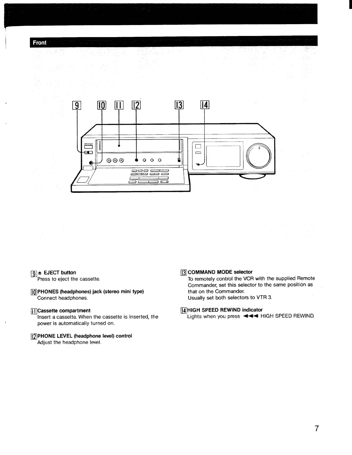
Sony SLV-575UC User manual

S
O
N
Y.
3-751
-783-23
(1)
Video
Cassette
Recorder
Operating
Instructions
VHS
o
fl
1
/
o
VHS!
[lie
lFa
CKING/
SPEED
REWIND
PRO
4
HEAD
DIGITAL
AUTO
TAACKING/HIGH
SPE
DA
©1990
by
Sony
Corporation

To
prevent
fire
or
shock
hazard,
do
not
ex-
For
the
customers
in
the
U.S.A.
pose
the
unit
to
rain
or
moisture.
INFORMATION
This
equipment
generates
and
uses
radio
frequency
energy
and
if
not
installed
and
used
properly,
that
is,
instrict
accordance
with
the
manufacturers
CAUTION
instructions,
may
cause
interference
to
radio
and
RISK
OF
ELECTRIC
SHOCK
television
reception.
It
has
been
type
tested
and
found
to
comply
with
the
limits
for
a
Class
B
computing
device
in
accordance
with
the
specifica-
tions
in
Subpart
J
of
Part
15
of
FCC
Rules,
which
are
designed
to
provide
reasonable
protection
against
such
interference
in
a
residential
installation.
DO
NOT
REMOVE
COVER
(OR
BACK)
_
However,
there
is
no
guarantee
that
inteference
will
;
hot
occur
in
a
particular
installation.
If
this
REESE
HSE
WISE
SOrE
PARIS
INBIDE
|
equipment
does
cause
interference
to
radio
or
REFER
SERVICING
TO
QUALIFIED
SERVICE
PERSONNEL.
[im
|
television
reception,
which
can
be
determined
by
'
turning
the
equipment
off
and
on,
the
user
is
encouraged
to
try
to
correct
the
interference
by
one
or
more
of
the
following
measures:
Reorient
the
receiving
antenna
CAUTION
:
TO
REDUCE
THE
RISK
OF
ELECTRIC
SHOCK,
|
This
symbot
is
intended
to
alert
the
Relocate
the
equipment
with
respect
to
the
user
to
the
presence
of
uninsulated
receiver
“dangerous
voltage”
within
the
prod-
More
the
equipment
away
from
the
receiver
uct's
enclosure
that
may
be
of
suffi-
H
Piug
the
equipment
into
a
different
outlet
so
that
cient
magnitude
to
constitute
a
risk
of
equipment
and
receiver
are
on
different
branch
electric
shock
to
persons.
circuits.
If
necessary,
the
user
should
consult
the
dealer
or
an
This
symbol
is
intended
to
alert
the
experienced
_radio/television
technician
for
user
to
the
presence
of
important
additional
suggestions.
The
user
may
find
the
operating
and
maintenance
(servicing)
following
booklet
prepared
by
the
Federal
instructions
in
the
literature
accompa-
Communications
Commission
helpful:
nying
the
appliance.
“How
to
identify
and
Resolve
Radio-TV
Interference
Problems”.
This
booklet
is
available
from
the
US.
Government
Printing
Office,
Washington,
DC
20402,
Stock
No.
004-000-00345-4.
CAUTION
TO
PREVENT
ELECTRIC
SHOCK,
DO
NOT
USE
THIS
POLARIZED
AC
PLUG
WITH
AN
EXTENSION
CORD,
RECEPTACLE
OR
OTHER
OUTLET UNLESS
THE
BLADES
CAN
BE
FULLY
INSERTED
TO
PREVENT
BLADE
EXPOSURE.
Owner's
Record
The
model
number
is
located
at
the
front.
The
serial
number
is
located
on
the
top
of
the
panel.
Record
the
serial
number
in
the
space
provided
right.
Refer
to
them
whenever
you
call
upon
your
Sony
deater
Serial
No.
regarding
this
product.
Model
No.
SLV-575UC

BE
o)(-We)
M@re)
ni
(cla
rf
PRELIMINARIES
PREPARATION
OPERATION
OTHER
INFORMATION
PIOCautions:
2x32
Poni
ota
OM
WG
Pat
toc
eta
aa
ete
ore
6
oe
hl
4
TATTODUCHION
ast
faces
8!
Soe
eds
che
Sa
adh
Epwaaciialidts
PMA
oud
ates
eile
states
Behe
5
Identifying
the
Operational
Parts
2.2.0.0...
2.
ccc
cc
cect
e
cece
ese
eeees
6
CONMECHONS
lee
So
petiheeed
Lik
se
ek
ack
Seat
Gctscted
aedia-a
seeker
Rasa
atdichyuelieiets
12
rao
(UEsi
(1a
©
pt
bs
|hY
Apeei
say
ant
at
ae
Ree
Sale
ee
On
19
M@nUSYSteMi
simian
he
hig
Satine
otras
came
eg
eck
a0
Des
ee
alloy
Te
ntieaed
aot
Aer
Se
atte
20
Mode
Setting)
cece
ec
doses
oon
taaiean
ete
i
Rad
actin
Prato
deenye
in
dean
Ue
pede
od
dae
22
Datée:and'
Clock
Setting
2
dcccastu
ak
ale
ee
Say
od
Seen
hae
bd
wed
eaee
wah
ele
gies
24
Presetting
Active
Channels
.......0..0.000
0000.
c
ccc
ccc
eect
eee
eneeey
26
Handling
Video
Cassettes...
0.0020.
e
teen
eeneenes
29
PLAYBACK
Playinig'a
Tapes
2.27
ccs
orc
ates
garadtne
bo
a
ks
Bie
tae
tle
ivi
states
aoCatons
BSE
Miehecedttecae!
30
RECORDING
Recording
TV
Programs:
snc
c
se
eet
he
na
Dose
eae
dda
Dutdw
died
dace
due
kc
eb
ela
37
Use.of
the:
Tape
Gount@t
sz
20.c.sthandis
dan
hande
AOS,
wee
tie beg
eh
oA
wa
Pe
hd
naee:
42
MIMEMRECOMING
puree
epee,
Beas
ccheity
tet
os
islne
ached
wanen
hae
Flv
els
acsdcboe
bocateiee
aoe,
one
44
Quick-TimerRecording
|
i...
gis
Son
etter
sleek
ednes
aia
eucijua
ch
@pacel
hud
Senne
he
Seca
52
INGEX
FUNCTION
fod
sucht
Seon
ae
cn
ca
ed
OAs
Men
arenes
eh
A
eA
ta
i
oe
et
54
AUGIOSRECOMING)..
v6.8
cite
oe
tea
eet
eRe
wt
ecnan
Wis
Say
we
edadatee
dada
ek
bans
56
EDITING
Editing
with
Another
VCR
..
0.0...
cece
cece
eee
e
nnn
neeteennnnes
58
Indications
in
the
Display
Window
............0.0
0.00.
cece
cece
e
eens
ccneveeus
61
TROUDIESNOOING
ieee
Bieeistns
Fook
eds
eile
a
RPh
Sg
Gxewabawtdl
Aoki
eetintod
aiked
62
DECITICALIONS
oars
cs
cece
teat
se
diareeha
yee
ue
eband
ater
dle
duos
Remote
ad
Aocwe
back
cover

Preliminaries
Precautions
On
Safety
¢Operate
the
unit
only
on
120V
AC,
60Hz.
eShould
anything
fall
into
the
cabinet,
unplug
the
unit
and
have
it
checked
by
qualified
personnel
before
operating
it
any
further.
eOne
blade
of
the
plug
is
wider
than
the
other
for
the
purpose
of
safety
and
will
fit
into
the
power
outlet
only
one
way.
If
you
are
unable
to
insert
the
plug
fully
into
the
outlet,
contact
your
dealer.
eUnplug
the
unit
from
the
wall
outlet
if
it
will
not
be
used
for
an
extended
period
of
time.
To
disconnect
the
cord,
pull
it
out
by
the
piug.
Never
pull
the
cord
itself.
On
Installation
eAllow
adequate
air
circulation
to
prevent
internal
heat
build-up.
*Do
not
place
the
unit
on
surfaces
(rugs,
blankets,
etc.)
or
near
materials
(curtains,
draperies)
that
may
block
the
ventilation
slots.
©Do
not
install
the
unit
near
heat
sources
such
as
radiators
or
air
ducts,
or
in
a
place
subject
to
direct
sunlight,
excessive
dust,
mechanical
vibration
or
shock.
The
unit
is
designed
for
operation
in
a
horizontal
position.
Do
not
install
it
in
an
inclined
position.
¢Keep
the
unit
and
cassette
tapes
away
from
equipment
with
strong
magnets,
such
as
microwave
ovens
or
large
loudspeakers.
*Do
not
place
any
heavy
object
on
the
unit.
eWhen
the
unit
is
not
in
use,
turn
the
power
off
to
conserve
energy
and
to
extend
the
life
of
the
unit.
eRemove
and
store
video
cassettes
after
recording
or
playback.
eStore
the
cassettes
in
their
cases
and
keep
them
in
an
upright
position
to
prevent
intrusion
of
dust
and
uneven
winding.
On
Cleaning
eClean
the
cabinet,
panel
and
controls
with
a
dry,
soft
cloth,
or
a
soft
cloth
slightly
moistened
with
a
mild
detergent
solution.
¢Do
not
use
any
type
of
solvent,
such
as
alcohol
or
benzine,
which
might
damage
the
finish.
On
Repacking
Do
not
throw
away
the
carton
and
packing
materials.
They
make
an
ideal
container
in
which
to
transport
the
unit.
When
shipping
the
unit
to
another
location,
repack
it
as
illustrated
on
the
carton.
If
you
have
any
questions
about
this
unit,
contact
your
Sony
dealer
or
qualified
technician.
Before
You
Begin
'
(]
Check
that
the
following
accessories
are
in
the
carton
with
your
VCR:
eRemote
Commander
RMT-V575A
(1)
eSize
AA
(R6)
batteries
(2)
eExternal
antenna
connector
(1)
¢75-ohm
coaxial
cable
with
F-type
connectors
(1)
¢Audio/video
connecting
cable
(1)
C1
In
the
text
of
this
manual,
the
buttons
and
switches
are
shown
in
capital
letters.
Example:
Press PLAY.
CJ
The
buttons
on
the
Commander
and
the
VCR
with
the
same
mark
have
the
same
functions.
OC
Notes
are
enclosed
in
boxes.

Falicerel
Coat
(ola)
How
to
Use
This
Manual
This
manual
is
arranged
to
help
you
quickly
find
the
information
you
need
for
the
operation
of
the
SLV-575UC.
This
manual
consists
of
the
following
4
sections.
1
Preliminaries
2
Preparation
3
Operation
4
Other
Information
First,
look
through
the
Table
of
Contents.
If
you
are
already
familiar
with
VCR
operation,
read
starting
from
the
“Preparation”
section.
If
you
are
new
to
VCR
operation,
start
with
“Identifying
the
Operational
Parts”
to
familiarize
yourself
with
this
VCR.
To
have
a
quick
overview
of
the
operation
of
this
VCR,
refer
to
“Playing
a
Tape”
(page
30),
“Recording
TV
Programs”
(page
37),
and
“Timer
Recording”
(page
44).
Overview
of
the
SLV-575UC
.
Tape
editing
Video/audio
input
jacks
on
front
panel
Offer
easy
connection
to
another
VCR.
Control
S
input
Allows
this
VCR
to
be
remotely
controlled
by
other
equipment
connected.
On-screen
display
AUTO
MENU
Displayed
to
set
the
VCR
to
the
desired
automatic
tape
operation.
AUTO
REPEAT
Allows
to
play
back
the
desired
portion
of
the
tape
repeatedly.
Data
screen
Displays
tape
counter,
tape
speed,
remaining
tape
length,
current
date
and
time,
etc.
Timer
title
Just
before
a
timer
recording
starts,
the
date,
time
and
channel
of
the
program
are
recorded.
Other
convenient
functions
=
AUTO
TRACKING
function
Automatically
adjusts
the
tracking
condition
for
optimum
picture.
SWING
SHUTTLE
ring
Allows
quick
access
to
the
desired
scene.
Function
memory
Enables
starting
of
the
desired
tape
operation
with
a
press
of
the
button.
High-quality
picture/sound
High-quality
picture
The
SLV-575UC
provides
sharp,
finely
detailed
pictures
through
High
Quality
picture
technology.
HQ:
The
video
cassette
recorder
(VCR)
with
this
marking
incorporates
VHS
high-quality
picture
technology
and
is
compatible
with
any
video
cassette
recorder
bearing
the
VHS]
mark.
High
quality
sound
This
VCR
automatically
performs
hi-fi
recordings.
Dynamic
range:
More
than
90
dB
Wow
and
flutter:
Less
than
0.005%
Audio
frequency
response:
20
—
20,000
Hz
Reproduces
clear
sound
SOMEUILUNAL
Y

Identifying
the
Operational
Parts
POWER
switch
and
indicator
[5|AUTO
TRACKING
indicator
Press
to
turn
on
the
power
of
the
VCR.
The
indicator
Blinks
while
the
VCR
is
searching
for
the
best
tracking
lights
when
power
is
supplied.
position.
Lights
when
the
best
position
is
obtained.
LINE
IN
2
VIDEO/AUDIO
jacks
(phono
type)
Connect
to
the
video/audio
output
of
other
VCR
or
[6
]Remote
sensor
video
camera.
Point
the
supplied
infrared
Remote
Commander
RMT-V575A
here.
SHARPNESS
control
Adjust
the
sharpness
of
the
playback
picture
if
[7
Display
window
necessary.
Normally
set
this
control
at
the
center
See
“Indications
in
the
Display
Window.”
(page
61)
indented
position.
[8]SWING
SHUTTLE
ring
[4]REC
LEVEL
controls
Turn
to
select
the
playback
speed
during
playback
or
in
Adjust
the
audio
recording
level.
Normally
set
these
recording
pause
mode.
controls
to
the
El
position.
\Oo}

GS
tw
@
(9]*
EJECT
button
([3]
COMMAND
MODE
selector
Press
to
eject
the
cassette.
To
remotely
control
the
VCR
with
the
supplied
Remote
Commander,
set
this
selector
to
the
same
position
as
(IPHONES
(headphones)
jack
(stereo
mini
type)
that
on
the
Commander.
Connect
headphones.
Usually
set
both
selectors
to
VTR
3.
{]
Cassette
compartment
([4]HIGH
SPEED
REWIND
indicator
Insert
a
cassette.
When
the
cassette
is
inserted,
the
Lights
when
you
press
<<<
HIGH
SPEED
REWIND.
power
is
automatically
turned
on.
{[2|PHONE
LEVEL
(headphone
level)
control
Adjust
the
headphone
level.

identifying
the
Operational
Parts
Li} (2)
(3)
14)
[6]
i
tj
[1]
TIMER
REC
ON/OFF
button
(6
|
TRACKING
AUTO/MANUAL
button
Press
to
set
the
VCR
to
timer
recording
standby
Press
to
reactivate
the
automatic
tracking
function
mode.
after
adjusting
tracking
manually.
When
changing
or
canceling
a
timer
recording,
or
operating
the
unit
before
a
timer
recording
starts,
TRACKING
NORMAL/SLOW
and
STILL
ADJUST
press
this
button
to
get
out
of
timer
recording
buttons
standby
mode.
Press
either
of
the
buttons
to
clear
streaks
that
may
appear
on the
screen
during
normal
or
slow
speed
ANT
TV/VTR
button
playback
or
to
reduce
picture
shaking
in
still
mode.
Press
so
that
the
VTR
indicator
lights
to
watch
a
program
selected
on
the
VCR.
To
watch
one
TV
[8]
®
REC
button
program
while
recording
another,
press
this
button
Press
to
start
recording.
again
to
turn
off
the
indicator.
[9]
Tape
transport
buttons
INPUT
SELECT
button
<4<@
REW
(rewind),
>
PLAY,
»
FF
(fast-forward),
Press
so
that
the
desired
input
mode
indicator
@
STOP.
a/ee
PAUSE/STILL,
appears
in
the
display
window
to
select
the
program
~<4<4<@
HIGH
SPEED
REWIND
to
be
recorded.
The
indicator
changes
as
follows.
=
QUICK
TIMER
button
TUNER
2
(channel
number)
-————|_
LINE
L1
Press
to
start
quick
timer
recording
and
to
set
the
‘a
recording
duration.
——-|
LINE
L2
|
({])
EDIT
ON/OFF
button
(4]
REC
MODE
button
Normally
keep
this
button
at
OFF
(ie.
the
EDIT
Press
to
select
the
recording
tape
speed,
SP
or
EP.
indicator
is
off
in
the
display
window).
When
using
this
VCR
for
editing,
press
this
button
to
light
the
CHANNEL
+/-
buttons
EDIT
indicator.
Press
to
select
the
preset
channels.
Press
+
to
advance
and
-
to
reverse.

Rear
Panel
o
im
VHF/UHF
IN
and
OUT
connectors
(F
type)
(5]
MONITOR
OUT
AUDIO
and
VIDEO
jacks
(phono
type)
Connect
to
the
LINE
IN
jacks
on
a
TV.
The
VCR
CONTROL
S§
IN
jack
(mini
type)
displays
on-screen
display
on
the
TV
or
monitor
Connect
to
the
CONTROL
§S
output
jack
of
a
Sony
through
this
connection.
TV
set
or
TV
tuner
to
operate
the
VCR
by
remote
control
through
them.
[6]
AC
power
cord
Also
connect
to
the
CONTROL
S
output
jack
of
another
Sony
VCR
for
synchronized
editing.
RF
UNIT
selector
Use
to
select
the
channel
for
VCR,
3CH
or
4
CH,
LINE
IN
1
AUDIO
and
VIDEO
jacks
(phono
type)
whichever
is
not
active
in
your
area.
Connect
to
the
LINE
OUT
AUDIO
and
VIDEO
jacks
of
other
video
equipments.
LINE
OUT
AUDIO
and
VIDEO
jacks
(phono
type)
Connect
to
the
LINE
IN
AUDIO
and
VIDEO
jacks
of
other
video
equipments.
If
you
connect
the
TV
to
these
jacks,
on-screen
display
does
not
appear.

Identifying
the
Operational
Parts
Remote
Commander
[|]
COMMAND
MODE
selector
To
remotely
control
the
VCR
with
the
Commander,
set
this
selector
to
the
same
position
as
that
on
the
VCR.
Usually
set
both
selectors
to
VTR
3.
Change
the
position
as
shown
below
to
control
other
Sony
VCRs.
VTR
1:
For
Sony
Betamax
VCRs
VTR
2:
For
Sony
8mm
format
VCRs
VTR
3:
For
Sony
VHS
format
VCRs
INPUT
SELECT
button
Press
to
select
the
sources
to
be
recorded.
The
selected
input
mode
indicator
appears
in
the
display
window.
[3]
REC
MODE
button
Press
to
select
the
recording
tape
speed,
SP
or
EP.
[4]
Menu
operation
buttons
Press
MENU
to
display
or
erase
the
main
MENU.
Press
</P»/A/¥
to
move
the
cursor
or
change
the
setting
and
press
EXECUTE
to
store
the
setting.
5|
FUNCTION
MEMORY
button
Press
to
execute
one
of
the
sequential
tape
operations
in
the
FUNCTION
MEMORY
menu
assigned
to
this
button.
10
[6]
ANT
TV/VTR
(Antenna
TV/VTR)
button
Press
to
light
the
VTR
indicator
in
the
display
window
to
watch
the
playback
picture
or
the
TV
program
selected
on
the
VCR.
When
you
want
to
watch
a
TV
program
while
the
VCR
is
in
use,
press
this
button
again
to
turn
off
the
VTR
indicator.
This
button
is
effective
when
your
TV
is
connected
to
the
VCR
via
the
VHF
antenna
terminal
only.
POWER
switch
TVIVTR
selector
Set
to
TV
when
you
use
the
supplied
Commander
to
operate
a
TV
and
to
VTR
to
operate
a
VCR.
DATA
SCREEN
button
Press
to
erase
or
display
the
on-screen
display.
COUNTER
RESET
button
Press
to
reset
the
counter
number
to
OHOOMOOS.
Channel
number
and
ENTER
buttons
Press
the
appropriate
button(s)
and
ENTER
to
select
the
channel
directly.
For
example,
to
select
channel
10,
press
1,
0
and
ENTER
or
to
select
channel
4,
press
4
and
ENTER.

ae
&
TIMER
CLEAR
button
Press
to
clear
the
memory
of
the
timer
settings.
TIMER
REC
ON/OFF
button
Press
to
enter
timer
recording
standby
mode.
Tape
transport
buttons
au
PAUSE
@
REC
(Press
two
buttons
simultaneously.)
SLOW
(+:
for
faster
speed,
—:
for
slower
speed)
<
,
>
DIRECTION
(Press
to
decide
the
direction
of
B®
PLAY,
x2
and
SLOW.
In
playback
still
mode,
frame-by-
frame
picture
is
available
with
this
button.)
x
2
(double
speed)
@)/@43
SEARCH
(reverse/forward)
m
PLAY
~@<@
REW
(rewind)
bP
FF
(fast-forward)
mSTOP
~<4<@
HIGH
SPEED
REWIND
AUDIO
MONITOR
button
Press
to
select
the
monitor
sound.
VOL
(volume)
+/-
buttons
Press
to
adjust
the
volume
of
the
TV.
CHANNEL
+/-
buttons
INDEX
button
Press
to
enter
the
index
function
mode.
INDEX
MARK/ERASE
buttons
Press
to
mark
or
erase
an
index
signal
on
a
tape
during
recording
or
playback.
Battery
insertion
1
Open
the
lid.
i
2
Insert
two
size
AA
(IEC
designation
on
R6)
batteries
|
with
the
polarity
lined
up
correctly.
:
Notes
on
batteries
|
With
normal
operation,
the
batteries
last
for
approximately
6
months.
elf
the
Commander
is
not
to
be
used
for
a
long
period
of
time,
remove
the
batteries
to
avoid
possible
damage
from
battery
leakage.
11

@reyalarzve1
(ce)
ats)
{In
order
to
watch
the
playback
picture
on
the
TV
screen
and
receive
TV
programs
on
this
VCR,
the
VCR
and
the
Before
You
Begin
TV
must
be
connected
properly.
The
connections
vary
depending
upon
the
type
of
TV
and
Turn
off
the
power
of
the
VCR
and
the
TV.
antenna
that
you
have.
¢Do
not
connect
the
AC
power
cords
until
you
complete
We
will
show
you
here
some
typical
ways
you
can
make
all
of
the
connections.
these
connections
with
the
supplied
accessories.
*If
your
TV
does
not
match
the
three
examples
below
Before
operating
the
VCR,
read
through
this
section
and
Consult
your
nearest
Sony
dealer
or
qualified
technician.
make
the
correct
connections.
Basic
connections
c
7]
75-ohm
VHF/UHF
antenna
terminal
©
VHF/UHF
Check
the
antenna
>
-
jana
Read
through
“Connecting
terminals
on
your
TV
VHF
and
UHF
separate
antenna
Examples
1
to
5.”
terminals
uuE
=)
©
VHF
©
Additional
connections
[—
Yellow
VIDEO
You
can
enjoy
better
picture
If
your
TV
has
video
and
quality.
audio
input
jacks
wma
Ae
ja
Read
through
“Connecting
AUDIO
Example
6.”
Red
You
can
enjoy
better
sound
quality
by
connecting
the
VCR
yon
eae
RT
(0
the
audio
system.
Read
audio
system
through
“Connecting
Example
7"
Caution
|
Connections
between
the
recorder
VHF/UHF
OUT
Commission
regarding
the
use
and
operation
of
rf
connector
and
the
antenna
terminals
of
a
TV
receiver
devices.
should
be
made
only
as
shown
in
the
instructions.
Never
connect
the
output
of
the
recorder
to
an
antenna
Failure
to
do
so
may
result
in
operation
that
violates
or
make
simultaneous
(parallel)
antenna
and
recorder
the
regulations
of
the
Federal
Communications
connections
at
the
antenna
terminals
of
your
receiver.
12

Connecting
Example
1
Connecting
Example
2
To
Connect
a
Combination
VHF/UHF
Antenna
To
Connect
a
VHF
Antenna
Only
If
the
antenna
cable
is
a
300-ohm
twin
lead
(flat)
type
Antenna
connector
|
=
(supplied)
if
the
antenna
cable
is
a
75-ohm
coaxial
(round)
type
|
!
F-type
connector
:
i
(not
supplied)
VHF/UHF
*
Use
an
RFC-8
external
cable
(not
supplied),
8m
(25
ft)
long,
if
the
supplied
75-ohm
coaxial
cable
is
not
long
enough.
F-type
connector
(not
supplied)
VHF/UHF
IN
ees
VHF/UHF
iN
VHF/UHF
OUT
75-ohm
coaxial
cable
*
(supplied)
75-ohm
coaxial
cable
EAC-66
U/V
L
(supplied)
band
separator
(mixer)
(not
supplied)
75-ohm
coaxial
cable
(supplied)
VHF/UHF
1
Disconnect
the
TV
antenna
cable
from
the
TV
and
1
Disconnect
the
TV
antenna
cable
from
the
TV
and
connect
it
to
the
VCR.
connect
it
to
the
VCR.
2
Connect
the
VCR
and
the
TV.
If
the
antenna
cable
is
a
75-ohm
coaxial
(round)
type
Use
an
F-type
connector
(not
supplied).
lf
your
TV
has
a
single
terminal
for
the
VHF/UHF
antenna
If
the
antenna
cable
is
a
300-ohm
twin
lead
(flat)
type
Connect
directly
using
the
supplied
75-ohm
coaxial
Use
the
antenna
connector
(supplied).
cable.
2
Connect
VHF/UHF
OUT
on
the
VCR
and
the
VHF
If
your
TV
has
separate
VHF/UHF
antenna
terminais
antenna
terminal
on
the
TV
with
the
75-ohm
coaxial
Use
a
U/V
band
separator.
cable
(supplied).
How
to
attach
the
U/V
band
separator
and
the
F-type
How
to
attach
the
antenna
connector
and
an
F-type
connector
connector
43
See
page
17.
See
page
17.

Connections
Connecting
Example
3
To
Connect
a
UHF
Antenna
Only
A
The
VHF/UHF
antenna
terminal
on
the
TV
is
combined
:
UHF
Antenna
connector
(supplied)
VHF/UHF
IN
75-ohm
coaxial
cable
(supplied)
VHF/UHF
1
Attach
the
supplied
antenna
connector
to
the
cable.
2
Attach
the
antenna
connector
to
VHF/UHF
IN
on
the
VCR.
3
Connect
VHF/UHF
OUT
on
the
VCR
and
the
VHF/UHF
antenna
terminal
on
the
TV.
14
The
VHF/UHF
antenna
terminals
on
the
TV
are
separated
UHF
Antenna
connector
(supplied)
VHF/UHF
IN
EAC-66
U/V
band
_separator
(mixer)
(not
supplied)
75-ohm
coaxial
cable
(supplied)
1
Attach
the
supplied
antenna
connector
to
the
cable.
2
Attach
the
antenna
connector
to
VHF/UHF
IN
on
the
VCR.
3
Attach
the
EAC-66
U/V
band
separator
to
VHF/UHF
OUT
on
the
VCR.
4
Connect
the
separator
to
the
VHF
and
UHF
antenna
terminals
on
the
TV.
How
to
attach
the
antenna
connector
and
the
U/V
band
separator
See
page
17.

Connecting
Example
4
To
Connect
Both
the
VHF
and
UHF
Antennas
A|
if
the
VHF/UHF
antenna
terminal
on
the
TV
is
combined
UHF VHF
EAC-66
U/V
band
separator
(mixer
(not
supplied)
F-type
connector
(not
supplied)
VHF/UHF
IN
75-ohm
coaxial
cable
(supplied)
VHF/UHF
1
Attach
a
U/V
band
separator
(mixer)
with
the
VHF
and
UHF
antennas
to
VHF/UHF
IN
on
the
VCR.
2
Connect
VHF/UHF
OUT
on
the
VCR
and
the
VHF/UHF
antenna
terminal
on
the
TV.
If
the
VHF/UHF
antenna
terminals
on
the
TV
are
separated
UHF
ool
VHF
EAC-66
U/V
band
separator
(mixer)
(not
supplied)
a
F-type
connector
(not
supplied)
VHF/UHF
IN
EAC-66
U/V
band
separator
(mixer)
(not
supplied)
75-ohm
coaxial
cable
(supplied)
1
Attach
an
U/V
band
separator
(mixer)
with
the
VHF
and
UHF
antennas
to
VHF/UHF
IN
on
the
VCR.
2
Attach
an
U/V
band
separator
to
VHF/UHF
OUT
on
the
VCR.
3
Connect
the
separator
to
the
VHF
and
UHF
antenna
terminals
on
the
TV.
How
to
attach
a
U/V
band
separator
and
an
F-type
connector
See
page
17.
15

Connections
Connecting
Example
5
To
Connect
a
Cable
TV
System
A\|
If
your
TV
set
has
a
builtin
CATV
decoder
CATV
75-ohm
coaxial
cable
F-type
connector
not
supplied
VHF/UHF
IN
Se
(not
supplied)
Y
VHF/UHF
OUT
75-ohm
coaxial
cable
(supplied)
EAC-66
U/V
band
separator
(mixer)
(not
supplied)
75-ohm
coaxial
cable
(supplied)
©
VHF/UHF
A
connecting
example
is
given
above,
however
you
should
consult
your
cable
company
to
make
sure
that
the
cable
is
properly
connected.
16
if
your
TV
set
does
not
have
a
built-in
CATV
decoder
CATV
75-ohm
coaxial
cable
F-type
connector
VHFIUHF
(not
supplied)
IN
75-ohm
coaxial
cable
(supplied)
CATV
channel
converter
VHFIUHF
Connect
the
cable
TV
channel
converter
between
the
TV
and
the
VCR.
By
setting
ANT
TV/VTR
to
TV,
you
can
watch
a
cabie
TV
program
while
playing
back
or
recording
video
sources
using
LINE
IN
VIDEO
on
the
VCR.
Note
to
CATV
system
installer
in
the
U.S.A
This
reminder
is
provided
to
call
the
cable
TV
system
installers
attention
to
Article
820-22
of
the
NEC
that
provides
guidelines
for
proper
grounding
and,
in
particular,
specifies
that
the
cable
ground
shall
be
connected
to
the
grounding
system
of
the
building,
as
close
to
the
point
of
cable
entry
as
practical.

Strip
the
cover
of
the
cable
so
that
3/8
inch
of
the
1
center
conductor
is
exposed.
aa
ton
10mm
(3/8
inch)
7mm
(1/4
inch)
Slip
the
crimping
ring
over
the
cable
and
fold
back
2
the
shield.
——
+
Insert
the
inner
conductor
into
the
F-type
3
connector
shaft
and
push
the
end
of
the
cable
into
the
connector
as
far
as
it
will
go.
F-type
connector
Cb
~+off)
Slide
the
crimping
ring
over
this
assembly
and
4
pinch
the
crimping
ring
with
pilars
to
hold
the
connector
in
place.
5
Cut
the
center
conductor.
3mm
(1/8
inch)
Insert
the
F-type
connector
into
VHF/UHF
IN
on
6
the
VCR.
)-
—
Gi)
VHF/UHF
IN
5
Last
e
external
antenna
connector
(supplied)
300-ohm
twin
lead
cable
screws
1
Loosen
the
screws
on
the
antenna
connector.
Fit
the
300-ohm
twin
lead
cable
on
the
UHF
antenna
under
the
screws
on
antenna
connector.
3
Tighten
the
screws
again.
Attaching
an
EAC-66
U/V
band
separator
(mixer)
|
(not
supplied)
VHF/UHF
IN
300-ohm
twin
lead
y
75-ohm
coaxial
cable
Loosen
the
screws
on
the
U/V
band
separator.
Fit
the
300-ohm
twin
lead
cable
on
the
UHF
antenna
under
the
screws.
Connect
the
75-ohm
coaxial
cable
to
the
U/V
band
separator.
Connect
the
U/V
band
separator
to
VHF/UHF
IN
on
the
VCR.
Bm
©
ND
—
17

Connections
Connecting
Example
6
To
Connect
a
TV
Equipped
with
Video/Audio
Input
Jacks
VHF/UHF
IN
el
}
“
“VHF/UHF
.
MONITOR
OUT
OUT.
Hf)
b}viDeo
MONITOR
OUT
AUDIO
Audio/video
connecting
cable
:
(supplied)
eae
AUDIOg
:
NAR
Uy
VIDEO
IN
If
your
TV
has
video/audio
input
jacks,
connect
them
to
the
MONITOR
OUT
jacks
on
the
VCR
to
obtain
a
higher
quality
picture.
1
Make
connections
between
an
antenna
and
VHF/UHF
IN
on
the
VCR,
and
between
VHF/UHF
OUT
on
the
VCR
and
the
antenna
terminal
on
the
TV
following
examples
1
to
5.
2
Connect
MONITOR
OUT
on
the
VCR
and
the
video/
audio
input
jacks
on
the
TV
with
the
supplied
audio/
video
connecting
cable.
18
Connecting
Example
7
To
Connect
an
Audio
System
Audio
system
to
auxiliary
input
’
or
tape
inputs
of
the
amplifier
to
recording
outputs
of
=
the
amplifier
RK-C74
i
LINE
IN
4
(or
2)
(not
supplied)
AUDIO
LINE
OUT
MONITOR
OUT
§3
£3
MONITOR
OUT
AUDIO
¥
VIDEO
Audio/video
connecting
cable
(supplied)
AUDIO
IN
{)
Color
monitor
You
can
enjoy
tapes
recorded
in
hi-fi
stereo
when
the
VCR
is
connected
to
your
audio
system.
Notes
elf
the
VCR
is
installed
near
a
tuner
or
a
radio,
noise
may
be
heard
in
AM
reception.
In
this
case,
move
the
VCR
away
from
the
tuner
or
the
radio,
adjust
the
AM
antenna
for
minimum
noise,
or
connect
an
external
AM
antenna
to
the
tuner.
¢Since
a
hi-fi
recorded
tape
has
a
wide
dynamic
range,
turn
down
the
volume
on
the
amplifier
before
playing
back
the
tape
to
avoid
damaging
the
i
speakers.
|
Before
connecting
or
disconnecting
the
power
cord
of
the
VCR,
be
sure
to
turn
off
the
connected
!
amplifier.

Adjusting
a
TV
ra
RF
UNIT
3CH
4CH
If
you
have
connected
your
VCR
and
TV
via
antenna
terminals
only,
either
channel
3
or
4
must
be
selected
on
your
TV
to
receive
the
signal
from
the
VCR.
To
get
the
proper
RF
signal,
set
the
RF
UNIT
selector
on the
rear
panel
of
the
VCR.
If
the
connection
between
the
VCR
and
TV
has
been
made
via
video/audio
jacks,
skip
this
step.
1
Set
RF
UNIT
to
3.
CH
or
4
CH.
lf
channel
4
is
active
in
your
area,
set
the
selector
to
channel
3,
and
vice
versa.
2
Press
POWER.
The
indicator
lights.
3
Press
ANT
TV/VTR
so
that
the
VTR
indicator
lights.
4
Check
that
the
TUNER
indicator
appears
in
the
display
window,
then
select
an
active
channel
in
your
area
by
pressing
CHANNEL
+/-.
5
turn
on
the
TV
and
select
either
VHF
channel
3o0r4
whichever
was
set
on
RF
UNIT.
The
TV
program
selected
on
the
VCR
appears
on
the
TV
screen.
Your
TV
is
now
tuned
to
receive
the
signal
from
the
VCR.
Whenever
you
use
the
VCR,
select
the
channel
you
choose
above
on
the
TV.
Note
For
details
about
TV
channel
setting,
see
the
instruction
manual
of
the
TV.
19

Menu
System
Many
of
the
operations
on
this
VCR
are
performed
using
First
display
the
main
MENU
and
select
the
item
you
want
amenu
system.
In
this
system
you
select
a
desired
item
to
operate
or
preset.
from
the
items
displayed
on
the
TV
screen.
How
to
Display
the
Main
MENU
Before
you
begin
Operation
eCheck
the
connection
between
the
VCR
and
the
TV.
lf
your
TV
is
equipped
with
video/audio
input
jacks,
be
1
Turn
on
the
TV.
sure
to
connect
them
to
MONITOR
OUT
on
the
VCR
for
If
your
TV
is
equipped
with
video/audio
input
jacks
on-screen
display.
On-screen
display
does
not
appear
if
Select
the
input
for
the
VCR.
the
TV
is
connected
to
LINE
OUT
VIDEO.
If
your
TV
is
not
equipped
with
video/audio
input
jacks
Select
the
channel
for
the
VCR
(3
or
4).
2
Press
POWER.
Press
ANT
TV/VTR
so
that
the
VTR
indicator
lights.
(Only
for
TV
without
video/audio
input
jacks)
4
Press
MENU.
The
main
MENU
appears.
AUTO
REPEAT
TIMER
SET/CHECK
MODE
SET
TUNER
PRESET
FUNCTION
MEMORY
CLOCK
SET
DEMONSTRATION
Cursor
MENU
5
Move
cursor
to
the
desired
menu
with
AUTO MENU
AorY.
AUTO
REPEAT
TIMER
SET/CHECK
MODE
SET
TUNER
PRESET
FUNCTION
MEMORY
»CLOCK
SET
DEMONSTRATION
Example
6
Press
EXECUTE.
The
selected
menu
ClOCh
BET
:
display
appears.
SiG
11990
MON
AM12:00
t
To
erase
the
menu
display
Press
MENU
again.
To
display
another
menu
display
Press
MENU
to
erase
the
present
menu
and
repeat
steps
4
to
6.
|
The
position
of
the
cursor
is
stored
unless
the
|
power
plug
is
disconnected.
20
Other manuals for SLV-575UC
1
Table of contents
Other Sony VCR System manuals

Sony
Sony SLV-765HF User manual

Sony
Sony SLV-ED313MJ User manual

Sony
Sony HDCAM-SR SRW5800 User manual

Sony
Sony SLV-XA127TK User manual

Sony
Sony DSR-20MD User manual

Sony
Sony SLV-SE610G User manual

Sony
Sony SLV-XA17ME User manual

Sony
Sony SE350K User manual

Sony
Sony SLV-GA59ME User manual

Sony
Sony EV-S3000 User manual

Sony
Sony DVCAM DSR-30P User manual

Sony
Sony SLV-SE240G/I User manual

Sony
Sony PVW-2650 User manual

Sony
Sony BVW-75 User manual

Sony
Sony HDW-1800 User manual

Sony
Sony SLV-798HF User manual

Sony
Sony SLV-M20HF - Video Cassette Recorder User guide

Sony
Sony Video Walkman GV-D900E User manual

Sony
Sony Digital Betacam DVW-2000P User manual

Sony
Sony SLV-757UC User manual