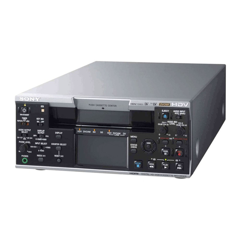
Sony DNW-A25WS User manual

DIGITAL VIDEOCASSETTE RECORDER
DNW-A25WS
DNW-A25WSP
OPERATION MANUAL
1st Edition [English]

WARNING
To prevent fire or shock
hazard, do not expose the
unit to rain or moisture.
To avoid electrical shock, do
not open the cabinet. Refer
servicing to qualified
personnel only.
For the customers in the USA
This equipment has been tested and
found to comply with the limits for a
Class B digital device, pursuant to Part
15 of th e FCC Rules. These limits are
designed to provide reasonable
protection against harmful interference
in a residential installation. This
equipment generates, uses, and can
radiate radio frequency energy and, if
not installed and used in accordance
with the instructions, may cause
harmful interference to radio
communications. However, there is no
guarantee that interference will not
occur in a particular installation. If this
equipment does cause harmful
interference to radio or television
reception, which can be determined by
turning the equipment off and on, the
user is encouraged to try to correct the
interference by one or more of the
following measures:
—Reorient or relocate the receiving
antenna.
—Increase the separation between
the equipment and receiver.
—Connect the equipment into an
outlet on a circuit different from that
to which the receiver is connected.
—Consult the dealer or an
experienced radio/TV technician for
help.
You are cautioned that any changes or
modifications not expressly approved
in this manual could void your authority
to operate this equipment.
The shielded interface cable
recommended in this manual must be
used with this equipment in order to
comply with the limits for a digital
device pursuant to Subpart B of Part
15 of FCC Rules.
For the customers in Europe
This product with the CE marking
complies with the EMC Directive (89/
336/EEC) issued by the Commission
of the European Community.
Compliance with this directive implies
conformity to the following European
standards:
• EN55103-1: Electromagnetic
Interference (Emission)
• EN55103-2: Electromagnetic
Susceptibility (Immunity)
This product is intended for use in the
following Electromagnetic
Environment(s):
E1 (residential), E2 (commercial and
light industrial), E3 (urban outdoors)
and E4 (controlled EMC environment,
ex. TV studio).

For the customers in the USA and
Canada
RECYCLING LITHIUM-ION
BATTERIES
You can help preserve our
environment by returning your used
rechargeable batteries to the collection
and recycling location nearest you.
For more information regarding
recycling of rechargeable batteries,
call toll free 1-800-822-8837, or visit
http://www/rbrc.org/.
Caution: Do not handle damaged or
leaking Lithium-Ion batteries.
RECYCLING NICKEL-CADMIUM
BATTERIES
You can help preserve our
environment by returning your used
rechargeable batteries to the collection
and recycling location nearest you.
Note: In some areas the disposal of
Nickel-Cadmium batteries in
household or business trash may
be prohibited.
For more information regarding
recycling of rechargeable batteries,
call toll free 1-800-822-8837, or visit
http://www/rbrc.org/.
Caution: Do not handle damaged or
leaking Nickel-Cadmium batteries.
Voor de Klanten in Nederland
•Dit apparaat bevat een vast
ingebouwde batterij die niet
vervangen hoeft te worden tijdens de
levensduur van het apparaat.
•Raadpleeg uw leverancier indien de
batterij toch vervangen moet worden.
De batterij mag alleen vervangen
worden door vakbekwaam
servicepersoneel.
•Gooi de batterij niet weg maar lever
deze in als klein chemisch afval
(KCA).
•Lever het apparaat aan het einde van
de levensduur in voor recycling, de
batterij zal dan op correcte wijze
verwerkt worden.


Table of Contents i
Chapter 1
Overview
1-1 Features ............................................................... 1-1
1-2 System Configuration......................................... 1-3
1-3 Locations and Functions of Parts...................... 1-4
1-3-1 Display Panel ...................................... 1-5
1-3-2 Control Panel.......................................1-7
1-3-3 Front Control Section........................1-18
1-3-4 Connector Panel ................................ 1-20
1-3-5 Top Panel .......................................... 1-24
Chapter 2
Preparations
2-1 Power Preparations ............................................ 2-1
2-1-1 Usable Batteries .................................. 2-1
2-1-2 Using the BP-L60A/L90A Battery
Pack.....................................................2-1
2-1-3 Using the BP-90A Battery Pack..........2-2
2-1-4 Using AC Power ................................. 2-4
2-2 Connection........................................................... 2-6
2-3 Handling Cassettes ............................................. 2-7
2-3-1 Loading/Ejecting Cassettes .................2-7
2-3-2 Preventing Accidental Erasures ........ 2-10
2-4 Setting Reference Video Signals...................... 2-11
2-5 Setting Timecode .............................................. 2-13
2-5-1 Setting an Initial Value and Recording
Timecode........................................... 2-14
2-5-2 Synchronizing the Internal Timecode
Generator with an External Signal .... 2-16
2-5-3 Synchronizing the Internal Timecode
Generator with Playback Timecode
– Timecode Recording during Auto
Editing ............................................... 2-17
2-5-4 Recording External Timecode without
Regeneration .....................................2-18
2-5-5 First Edit Function ............................2-18
2-6 Submenu Screen Display ................................. 2-19
2-6-1 Displays on the Home Page of
the Submenu......................................2-19
2-6-2 Submenu Basic Operations ...............2-21
Table of Contents
(Continued)

ii Table of Contents
Table of Contents
Chapter 2
Preparations
(continued)
2-7 Input and Output Settings for Video and
Audio Signals (Submenu)................................. 2-24
2-7-1 Making Settings in the Audio Settings
Pages .................................................2-24
2-7-2 Making Settings in the Audio Settings
Subpages ...........................................2-26
2-7-3 Making Settings in the Video Settings
Pages .................................................2-29
2-8 General Settings Pages of the Submenu ......... 2-32
Chapter 3
Editing
3-1 Selecting an Edit Mode ...................................... 3-1
3-1-1 Assemble Editing ................................ 3-1
3-1-2 Insert Editing....................................... 3-2
3-2 Finding Edit Points — Search ........................... 3-3
3-3 Setting Edit Points .............................................. 3-5
3-3-1 Setting Edit Points............................... 3-5
3-3-2 Checking Edit Points........................... 3-6
3-3-3 Cueing Up Edit Points.........................3-6
3-3-4 Previewing Edit Results ......................3-7
3-3-5 Modifying Edit Points......................... 3-8
3-3-6 Setting Edit Points Using the Recorder
Unit Only.............................................3-9
3-4 Executing an Edit ............................................. 3-10
3-4-1 Outline of Editing Operations ...........3-10
3-4-2 Starting an Edit..................................3-11
3-4-3 Redoing an Edit................................. 3-12
3-4-4 Displaying the Results of Editing ..... 3-12
3-5 DMC Editing ..................................................... 3-14
3-5-1 Overview of DMC Editing................ 3-14
3-5-2 Setting Edit Points and Playback
Speeds ...............................................3-15
3-5-3 Executing DMC editing ....................3-16
3-6 Preread Editing................................................. 3-17
3-7 Special Editing .................................................. 3-19
3-7-1 Quick Editing ....................................3-19
3-7-2 Continuous Editing ...........................3-20
3-7-3 Manual Editing.................................. 3-21

Table of Contents iii
Chapter 4
Recording
and
Playback
4-1 Recording ............................................................ 4-1
4-1-1 Preparations for Recording ................. 4-1
4-1-2 Recording Operation ...........................4-1
4-2 Sequential Recording ......................................... 4-2
4-3 Playback .............................................................. 4-4
4-3-1 Preparations for Playback ................... 4-4
4-3-2 Playback Operation ............................. 4-5
4-3-3 Capstan Override Playback.................4-6
Chapter 5
Shot Mark/
Shot Data
5-1 Overview of Shot Mark/Shot Data Function ... 5-1
5-1-1 Shot Mark Function Features.............. 5-1
5-1-2 Shot Mark Operation Menu ................ 5-2
5-1-3 Reading Shot Data ..............................5-3
5-2 Shot Mark Operations ....................................... 5-4
5-2-1 Reading Shot Marks............................ 5-4
5-2-2 Writing Shot Marks.............................5-4
5-2-3 Creating a Virtual Shot Mark.............. 5-5
5-2-4 Displaying Shot Mark List.................. 5-5
5-2-5 Deleting Shot Marks ........................... 5-8
5-2-6 Sorting Shot Marks ............................. 5-8
5-2-7 Cueing up a Mark................................ 5-9
Chapter 6
Setup
Menu
6-1 Menu System Configuration.............................. 6-1
6-2 Basic Menu .......................................................... 6-1
6-2-1 Items in the Basic Menu......................6-1
6-2-2 Basic Menu Operations.......................6-6
6-3 Extended Menu ................................................. 6-11
6-3-1 Items in the Extended Menu .............6-11
6-3-2 Extended Menu Operations............... 6-36

iv Table of Contents
Table of Contents
Appendixes Removing a Cassette When Tape Slack Occurs ..... A-1
Head Cleaning............................................................ A-1
Moisture Condensation ............................................. A-2
Digital Hours Meter .................................................. A-3
Specifications.............................................................. A-5
Information Displayed on the LCD Monitor ........ A-11
Combining Two VTRs ............................................ A-16
Using the Shoulder Belt........................................... A-18
Using the Carrying Case ......................................... A-19
Using the Soft Carrying Case ................................. A-20
Glossary .................................................................... A-22
Index .............................................................................I-1

Overview 1-1
Chapter 1 Overview
1-1 Features
Chapter 1 Overview
The DNW-A25WS/A25WSP is a
digital portable editing recorder for the
Betacam SX format. It is equipped
with a color LCD monitor and speaker
to enable editing of news material in
the field.
The features of this unit include the
following.
Betacam SX format
This unit supports the Betacam SX
format, developed by Sony as the
digital version of the Betacam SP
format. No format conversion is
needed for use with nonlinear editing
systems and server systems.
Playback compatibility with
Betacam SP
It can play tapes recorded in the
Betacam and Betacam SP formats,
allowing you to make effective use of
Betacam and Betacam SP cassettes
recorded in the past. You can
assemble news gathering systems that
combine this unit with conventional
Betacam SP camcorders.
Digital signal processing
This unit processes 4:2:2 component
digital signals in the D-1 format.
Inter-frame data compression
Inter-frame data compression by
MPEG2 4:2:2 Profile @ Main Level
(1 GOP = 2 frames) reduces the
volume of data to about 1/10.
Rich variety of input and
output signals
The following input and output signals
are supported.
• SDI (serial digital interface) video
and audio
• Analog composite video
• Analog audio
• Timecode
Powerful editing functions
Combining two DNW-A25WS/
A25WSP units allows you to perform
assemble editing, insert editing, and
audio split editing. DMC (dynamic
motion control) is possible when both
the source and recording sides use the
Betacam SX format.
This unit can also be connected to a
BVE series or other editor for remote
editing.
Sequential recording
Combining two DNW-A25WS/
A25WSP units allows you to perform
sequential recording from one unit to
another.
When you perform overwrite
recording using only two cassettes, the
last two hours recording can be
obtained at any time. When you
renew the cassette about every 1 hour,
endless recording is possible.

1-1 Features
1-2 Overview
Chapter 1 Overview
525 or 625 versatility
When using the Betacam SX format,
525 or 625 mode recording and
playback can be selected from a menu.
When using the Betacam and Betacam
SP formats, only simple viewing is
possible for tapes recorded in different
mode.
Combination of two units
Using the BKNW-225 to combine two
DNW-A25WS/A25WSP units gives
you a portable editor.
Economical
• Betacam SP cassettes and
inexpensive UVW cassettes can be
used in addition to Betacam SX
cassettes.
• Special high-durability heads and
components contribute to reduced
maintenance costs.
Compact and lightweight
Even though it is a standalone editing
recorder equipped with an LCD
monitor and a speaker, thanks to its
compact design and light weight, you
can carry it easily.
Switchable aspect ratio
You can switch the aspect ratio of
video signals displayed on the LCD
monitor between 16: 9 (edge crop
mode), 16: 9 (letter box mode) and
4: 3.
Good Shot marks/Shot Data
During tape rewinds, this unit reads
the REC Start (RS) and Good Shot
(GS) marks recorded by Betacam SX
camcorders, and builds an index. The
index facilitates quick cue-ups of
desired marks (index search function),
for greater editing efficiency.
When shot marks are recorded on the
tape, you can display and sort lists of
the shot marks.
Preread editing
You can execute preread editing,
using video or audio signals recorded
on the tape as the edit source for insert
editing. Using this function, the
previously read signals ca be sent to
mixers for mixing and returned to the
original channels.
AC and DC power
This unit is equipped with V-shoe
attachment, on which BP-L60A/L90A
or BP-90A battery or an AC adaptor
can be mounted. The unit can operate
for about 80 minutes with BP-L90A
battery mounted. For AC operation,
you can connect an AC-550/550CE or
AC-DN2B adaptor.

Overview 1-3
Chapter 1 Overview
1-2 System Configuration
The figure below shows an example of
an editing system configured around
the DNW-A25WS/A25WSP.
Betacam SX camcorder
Digital
cassette
Betacam SP
camcorder
Analog
cassette
Microphone
Video monitor
Audio monitor
Digital
modulator
Microwave
transmission system
Digital
demodulator
Protocol
converter Protocol
converter
DNW-A75 series
BVE series
editor
BVR-3
PLAYER
REMOTE
REMOTE/DC OUT
BATTERY/
DC IN
DC-L90 BP-90A
DC-210
BP-L90A
BP-L60A
AC-DN2B
AC-550/
550CE
VIDEO
OUT
DNW-A25WS/A25WSP
MONITOR OUT/
AUDIO OUT
DSM-M1
SDI
DSM-D1
SDI
SDI
SDI Network
Digital
cassette Headphones

1-3 Locations and Functions of Parts
1-4 Overview
Chapter 1 Overview
1-3 Locations and Functions of
Parts
This unit is comprised of the parts
shown in the figure below.
How to open the
display panel
Slide the lock release switch
and raise the display panel.
Display panel
(see page 1-5)
Control panel
(see page 1-7)
Front control section
(see page 1-18)
Connector panel
(see page 1-20)
Top panel (see page 1-24)

Overview 1-5
Chapter 1 Overview
1-3-1 Display Panel
1LCD monitor
Displays the playback or E-E pictures.
Time data, status information, and
setup menus, etc are superimposed on
the LCD monitor.
2BRIGHT (brightness)/
CONTRAST knob
Adjusts the brightness and contrast of
the LCD monitor 1. Adjustments
have no effect on the recorded or
output video.
3WARNING indicator
Lights when the battery is exhausted
or an error occurs.
It flashes in the following cases.
•When the end of battery power is
near
•When the number of memorized shot
marks reaches to 200 during shot
mark reading or when you start
reading shot marks after 200 marks
have been read.
•When the tape’s recording mode
does not agree with the playback
mode set on the unit (SP TAPE
switch position) during playback of a
Betacam SP tape if setup menu item
127 is set to ON (page 6-13).
4Timecode operation buttons
HOLD button: Stops the progress
of the timecode generator. Press
this button before setting
timecode or user bits to hold
those values.
RESET button: Resets the CTL,
TC, and U-BIT values displayed
in the submenu screen 9to 0.
Resetting the CTL value erase all
edit points that have been set.
For more information, see section 2-5
“Setting Timecode” (page 2-13).
1LCD monitor
2BRIGHT (brightness)/
CONTRAST knob
3WARNING indicator
4Timecode operation
buttons
5CTL/TC/U-BIT button
6WIDE/AU.MON switch
7METER switch
8Audio level meter
9Submenu screen
0UP and DOWN buttons
qa Audio monitor speaker
qs Submenu operation buttons F1 to F4
qd PAGE button

1-3 Locations and Functions of Parts
1-6 Overview
Chapter 1 Overview
5CTL/TC/U-BIT button
Alternately selects CTL (control), TC
(timecode), and U-BIT (user bits) as
the time data used in editing and
displayed in the submenu screen 9.
6WIDE/AU.MON (aspect ratio/
audio monitor output) switch
Selects audio monitor output channel
assignments or aspect ratios,
depending on whether the WID/MON
item of the submenu is set to
AU.MON or WIDE (see page 2-34).
When the WID/MON item of the
submenu is set to AU.MON, this
switch selects the signals assigned to
audio monitor outputs L and R.
1/2: Assign channel 1 to audio
monitor output L (left), and
assign channel 2 to audio monitor
output R (right).
MIX: Assign mixed signals from
channel 1 and channel 2 to audio
monitor outputs L and R.
2/1: Assign channel 2 to audio
monitor output L, and assign
channel 1 to audio monitor output
R.
When the WID/MON item of the
submenu is set to WIDE, this switch
selects the aspect ratio of playback
video signals or input video signals
displayed on the LCD monitor.
EDGE: Aspect ratio 16:9 (edge crop
mode)
L.BOX: Aspect ratio 16:9 (letter box
mode)
OFF: Aspect ratio 4: 3
7METER switch
Selects the audio channel whose level
is displayed by the audio level meter
8.
CH-1/2: Display the recording,
playback, and E-E levels of audio
channels 1 and 2.
CH-3/4: Display the recording,
playback, and E-E levels of audio
channels 3 and 4.
8Audio level meter
Displays the recording and playback
audio levels of two (CH-1/2 or CH-3/
4) of the four audio channels (CH-1 to
CH-4), as selected with the METER
switch 7.
9Submenu screen
Displays time data, status information,
submenu, setup menu and error
messages.
For more information about the
submenu, see section 2-6-1 “Displays
on the Home Page of the Submenu”
(page 2-19).
0UP and DOWN buttons
Press to make settings in the submenu.
Settings made by submenu include
video and audio input and output
settings, and reference video signal
settings. For details, see section 2-6-1
“Displays on the Home Page of the
Submenu” (page 2-19).

Overview 1-7
Chapter 1 Overview
1-3-2 Control Panel
Tape transport section (see page 1-8)
Audio control section (see page 1-16)
Editing section (see page 1-14)
Timecode and setup menu sections (see page 1-12)
REC INHI switch (tape transport section)
qa Audio monitor speaker
Plays the mixed audio signal of L and
R selected with the MONITOR L/R in
the submenu. Ajust the volume with
the LEVEL knob on the front control
panel. You cannot monitor sound from
the speaker when headphones are
connected to the HEADPHONES
jack.
For more information about the
MONITOR L/R, see page 2-26.
qs Submenu operation buttons F1
to F4
Select items in the submenu.
For more information about the
submenu, see section 2-6-1 “Displays
on the Home Page of the Submenu”
(page 2-19).
qd PAGE button
Switches between pages in the
submenu.
For more information about the
submenu, see section 2-6-1 “Displays
on the Home Page of the Submenu”
(page 2-19).

1-3 Locations and Functions of Parts
1-8 Overview
Chapter 1 Overview
Tape transport section
1PREROLL button
Press to run the tape up to the preroll
point (located in advance of the IN
point by the amount of the preroll
time). You can set the preroll time
using setup menu item 001. You can
set the state of the unit at the end of
preroll by using setup menu item 401.
By pressing this button at the same
time as the IN/OUT or AUDIO IN
buttons in the editing section, you can
search for a timecode set in advance
and stop at that position. (The tape is
cued up to the preset timecode
position.)
2REC INHI (recording inhibit)
indicator
Lights under the following situations.
• Set the REC INHI switch qh to ON.
• Press in the erasure prevention plug.
•Insert the Betacam SP cassette and
set the SP TAPE switch 5to SP PB
ONLY.
•Insert the Betacam cassette (oxide
tape).
qd PLAYER/DMC and RECORDER
buttons/indicators
qa Jog and shuttle dials
5SP TAPE switch
2REC INHI indicator
qs SERVO indicator
qf EJECT button
qh REC INHI switch
3REC/SEQ button
4EDIT button
qj Cassette compartment 7Search button and indicators
8STANDBY indicator
0PLAY button
9F FWD button
6STOP button
1PREROLL button
qg REW button

Overview 1-9
Chapter 1 Overview
When the REC INHI switch qh is set
to OFF, it is possible to set this
indicator flashing instead of lighting
under the latter three situations. For
details, see setup menu item 107 on
page 6-12.
3REC/SEQ (recording/sequence)
button
Press together with the PLAY button
0to start recording.
When two DNW-A25WS/A25WSP
units are combined, this button allows
you to perform sequential recording
from one unit to another.
For details, see 4-2 “Sequential
Recording” (page 4-2).
To monitor E-E mode
You can monitor input signals in E-E
mode by pressing this button from
stop mode. The button lights when
pressed. To return to the original
picture, press the STOP button 6.
You can view E-E video during
playback, search, fast forward, and
rewind by pressing this button. The E-
E video continues for as long as the
button is kept pressed.
4EDIT button
Press together with the PLAY button
0to perform manual editing.
To monitor E-E mode
You can monitor input signals in E-E
mode by pressing this button from
stop mode. The button lights when
pressed, and the input signals selected
with the ASSEMBLE or INSERT
buttons appear in E-E mode. To return
to the original picture, press the STOP
button 6. You can view E-E video
during playback, search, fast forward,
and rewind by pressing this button.
The E-E video continues for as long as
the button is kept pressed.
5SP TAPE switch
Selects the recording/playback format
when a Betacam SP cassette
(including UVW cassette) is loaded.
SX: Record or play back in Betacam
SX format.
SP PB ONLY: Play back in
Betacam SP format. (Recording
to a Betacam SP cassette is
impossible.)
Note
This switch does not function for
Betacam (oxide) and Betacam SX
cassettes. These cassettes are
distinguished automatically from the
Cassette ID hole when the cassette is
loaded.

1-3 Locations and Functions of Parts
1-10 Overview
Chapter 1 Overview
6STOP button
Press this button, lighting it, to stop
playback or recording. When you stop
playback, the LCD monitor displays
E-E or still picture playback,
depending on the settings of the
monitor output switches in the
timecode and setup menu section.
When setup menu item 105 is set to
ON (page 6-11), this button flashes if
the reference video signal specified in
the OUT REF item of the submenu
(page 2-29) and item 309 in the setup
menu (page 6-16) is not being input.
For more information about reference
video signal settings, see page 2-11.
7Search button and indicators
Press to enter search mode. (The JOG
or SHUTTLE indicator lights.)
When the unit is in jog or shuttle
mode, keep this button depressed for
about 1 second to enter variable mode.
(The both indicators light.) To return
to shuttle mode, keep this button
depressed again for about 1 second.
In shuttle or variable mode, you can
start playback at preset speed by
rotating the shuttle dial to the desired
position and pressing this button.
8STANDBY indicator
Lights when the tape drum is rotating
with tension applied (standby on). It
goes out when the drum stops rotating
and tension is released (standby off).
To protect the tape, the unit normally
changes to standby off when stop
mode continues for longer than eight
minutes. If you operate a dial or any of
the tape transport buttons except
STOP while the unit is in this state,
the unit changes to standby on and
enters the mode of the button or dial
that you pressed.
Press the ENTRY and STOP buttons
at the same time to switch between
standby on and standby off manually.
For more information about tape
protection, see the setup menu items in
the 500s on page 6-20.
9F FWD (fast forward) button
Press this button, lighting it, to fast
forward the tape.
When using a tape on which shot
marks have been recorded, you can
press this button together with the
TRIM –/LIST button to read shot
marks from the tape, and press this
button together with the TRIM +/
MARK button to cue up shot mark
positions.
For details, see Chapter 5 “Shot
Mark/Shot Data”.

Overview 1-11
Chapter 1 Overview
0PLAY button
Press this button, lighting it, to start
playback. Recording starts when you
press this button together with the
REC/SEQ button, and manual editing
starts when you press this button
together with the EDIT button. If you
press this button only during recording
or manual editing, recording or
manual editing stops and the unit
returns to playback mode.
This button is also used to display the
shot data if it is recorded on the tape.
For details, see 5-1-3 “Reading Shot
Data” (page 5-3).
qa Jog and shuttle dials
To search in shuttle or variable mode,
rotate the outer ring (shuttle dial). To
search in jog mode, press the inner
ring (jog dial) until it clicks and then
rotate. Rotate in the clockwise
direction to search in the forward
direction (the FORWARD indicator
lights), and rotate in the
counterclockwise direction to search
in the reverse direction (the
REVERSE indicator lights).
For more information about search,
see page 3-3.
qs SERVO indicator
Lights when the drum servo and
capstan servo are locked.
qd PLAYER/DMC and
RECORDER buttons/indicators
When two DNW-A25WS/A25WSP
units are combined and connected via
the REMOTE (9-pin) connectors,
press to control one unit from another.
PLAYER/DMC button: The
buttons of the editing and tape
transport sections on the recorder
side of the control panel work to
control the player unit.
You can also press this button
together with the ENTRY/SHIFT
button to put the combined units
into DMC edit mode.
For details, see 3-5 “DMC Editing”
(page 3-14).
RECORDER button: The buttons
of the editing and tape transport
sections on the recorder side of
the control panel work to control
the recorder itself.
qf EJECT button
Press to eject the cassette or open the
cassette compartment qj. The button
lights while the cassette is being
ejected. If you insert a cassette which
cannot be used on this unit, the button
flashes. Press the button to eject the
cassette.
qg REW (rewind) button
Press this button, lighting it, to rewind
the tape.
When using a tape on which shot
marks have been recorded, you can
press this button together with the
TRIM –/LIST button to read shot
marks from the tape, and press this
button together with the TRIM +/
MARK button to cue up shot mark
positions.
For details, see Chapter 5 “Shot
Mark/Shot Data”.

1-3 Locations and Functions of Parts
1-12 Overview
Chapter 1 Overview
2INT/EXT switch
3PRESET/REGEN switch
4F-RUN/R-RUN switch
5Monitor output switch
6MENU button
7SET button
1REMOTE/LOCAL switch
Selects the source for control of this
unit. When two DNW-A25WS/
A25WSP units are connected, set this
switch on the player unit to REMOTE.
REMOTE: This unit is controlled
from the device connected to the
REMOTE connector. In this case,
all VTR operations using this
unit’s control panel are disabled
except the STOP and EJECT
buttons.
LOCAL: This unit is controlled
from the control panel. Normally
set the switch to this position.
When the REMOTE is selected, you
can determine which tape transport
control buttons on the control panel
are enabled. See setup menu item 006
on page 6-3.
qh REC INHI switch
When on, recording to the tape is
inhibited, regardless of the state of the
cassette’s erasure prevention plug.
(The REC INHI indicator 2lights.)
qj Cassette compartment
Insert a cassette here. Press the EJECT
button qf to open the compartment.
Timecode and setup menu sections
Other manuals for DNW-A25WS
2
This manual suits for next models
1
Table of contents
Other Sony VCR System manuals

Sony
Sony SLV-SE10 User manual

Sony
Sony SL-HF550 User manual

Sony
Sony Video Walkman GV-D200 User manual

Sony
Sony SLV-E780EE User manual

Sony
Sony DCR-PC350 - Digital Handycam Camcorder User manual

Sony
Sony SLV-ED225 User manual

Sony
Sony SLV-740HF User manual

Sony
Sony SLV-SE240G/I User manual

Sony
Sony SLV-380 User manual

Sony
Sony SLV-E120AE User manual