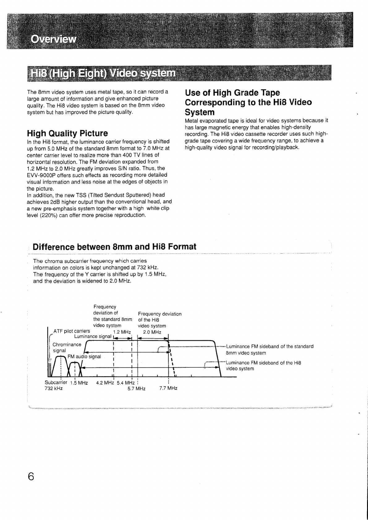
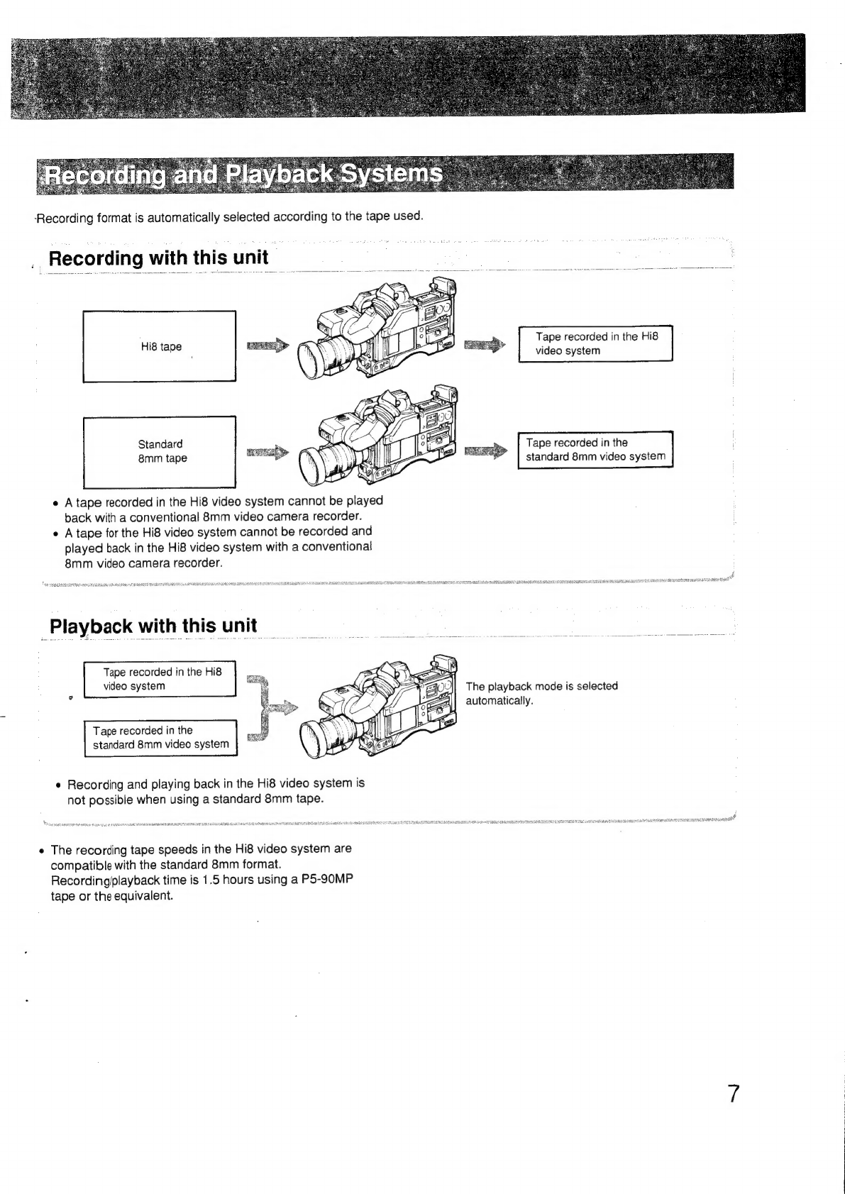
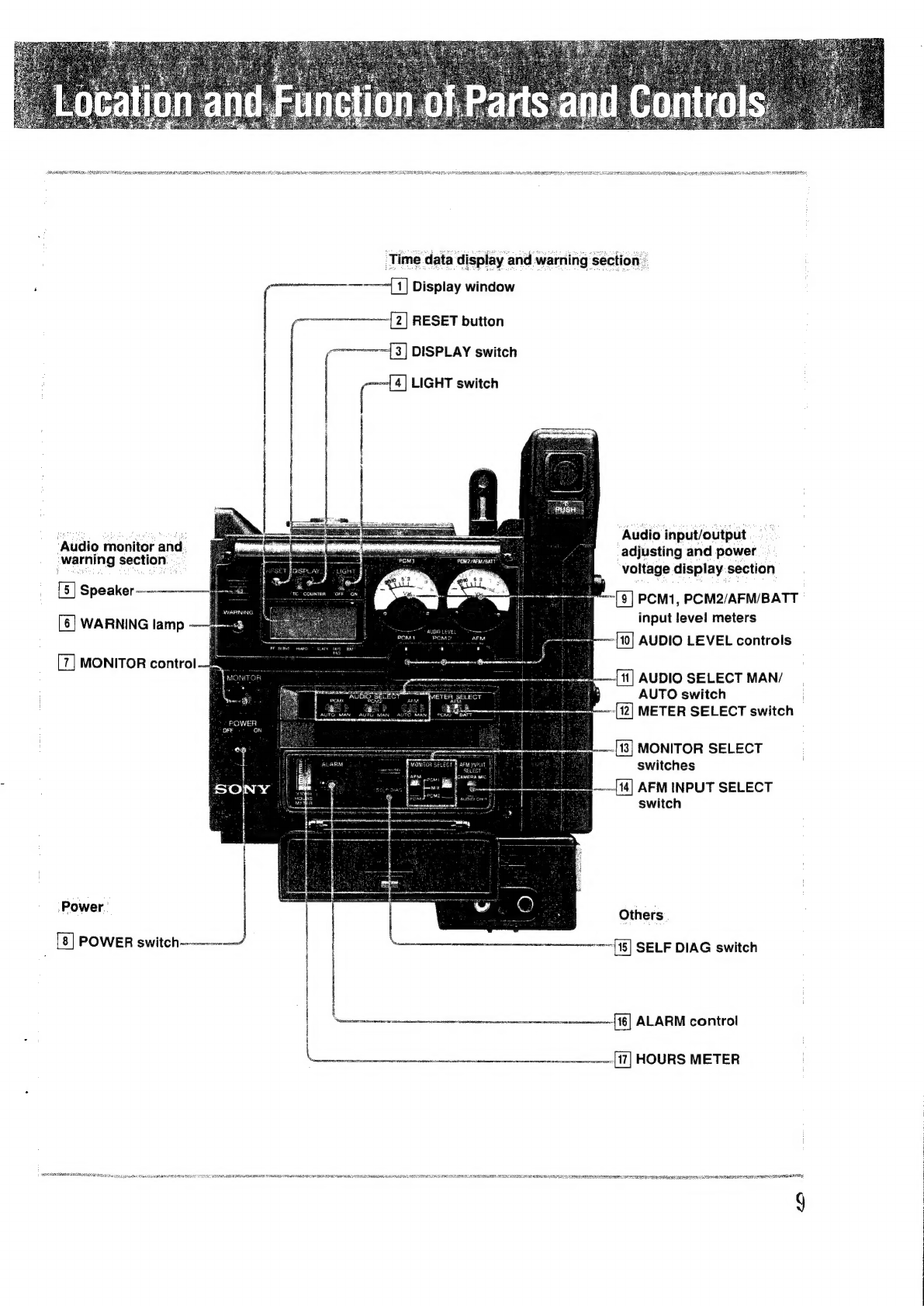
Sony Hi8 EVV-9000P User manual

Video
Cassette
Recor
EV
V-9000P
Istruzioni
per
Puso
pagina
104
Prima
diusare
l’'apparecchio,
leggere
con
attenzione
questo
manuale
e
conservarlo
per
riferimenti
futuri.
PLE
©
1990
by
Sony
Corporation

PEnish
To
prevent
fire
or
shock
hazard,
do
not
expose
the
unit
to
rain
or
moisture.
To
avoid
electrical
shock,
do
not
open
the
cabinet.
Refer
servicing
to
qualified
personnel
only.

OVEN
VIO
W
son
2cck.
feces
sesee
becca
ieenssatce
savas
vovedaviascusersavecsauseusuadebevssdea
sare
elageten
Seasetsessee
Features
APPIication
.......ceceeeescseseesesceseceeesenecseneeereseeeenesserarsesaneaaerseersaeraenaeneneeees
Hi8
(High
Eight)
video
system
............
Recording
and
playback
systems
PreCaUtiONS
oo...
cccccccceccsesescssseseseseneseseeeeeeneececssscsenesssesssesenessereasseessenseseseenatienes
Location
and
function
of
parts
and
controls
ASSOMDIY
uon..eceeecceeceecesesseeneseeessesesecneseeneseesesesesneneensaeeesnececaeensssareseaesenens
Assembling
the
VTR
and
the
DXC-325P
Attaching
the
shoulder
strap
Power
SOUICES
occ
settee
eeeeenee
Power
sources
available
with
this UNit
0.0.0...
ccc
ccceeeeeree
ener
settee
etseneeenenes
NP-1A/1B
battery
pack
AC:
POWER
isicidsccescceedteeecceees
Cassette
care
ou...
Cassette
in
use
...........
Cassette
INSErtion
......ccccccccssecccccssssseeceeeeseseaneeesssnsesasesssaeaeeeeeeeeeesesseeenenees
Recording
Playback
..0....cc
eee
Connecting
a
monitor
....
Operation
.......
eee
eee
Warning
SYSTOM
0.00...
ccc
sees
eseeseseeseseenesceeeneeneasaneaseneasseaeeaaneneneseenneneneneeys
Specifications
2...
eee
ceseeseeseeseeneseeneeseeneeneseenneaseecensaseseneseensnscaensety
TroubleShooting
...........
ccc
eetsenetseesneseseseersseeseeeessnnenecnensaaenecsssneseasereneesgens

The
EVV-9000P
is
a
Hi8
video
cassette
recorder
for
a
camcorder
dockable
to
the
DXC-325P
(3-chip
CCD
color
video
camera).
Hi8
format
for
high
quality
picture
The
Hi8
video
system
gives
much
better
picture
quality
than
standard
8
mm
video
system.
For
Hi8
recording,
Hi8
ME
(Metal
Evaporated)
videocassettes
must
be
used.
The
EVV-
9000P
is
provided
with
both
Hi8
and
standard
record/
playback
mode.
The
cassette
type
is
automatically
detected.
And
the
recorded
mode
is
also
automatically
detected
when
playback.
Y/C
separated
video
input
.
Conventionally,
video
equipment
exchanges
the
composite
video
signal
containing
the
luminance
(Y)
signal
and
the
chrominance
(C)
signal
mixed.
The
composite
video
signal
is
liable
to
produce
interference
resulting
in
picture
quality
loss.
The
EVV-9000P,
on
the
contrary,
uses
the
Y/C
separated
video
input,
which
minimizes
flickers
and
color
blur.
Sharpness
is
enhanced
to
such
an
extent
that
hair
and
fine
stripes
are
clearly
visible.
One
AFM
and
two
PCM
audio
channels
The
EVV-9000P
provides
high
quality
audio
with
its
monaural
AFM
and
stereo
PCM
recording
system.
Built-in
8
mm
time
code
generator
The
8
mm
time
code
is
recorded
onto
a
tape
for
precise
editing
reference.
8
mm
tape
format
The
video,
audio
and
time
code
signals
are
recorded
on
the
8
mm
video
tape
as
follows.
sO
a
ESN
HM
eR
SN
_
sO
AIR
SRNR
RT
RRR
RI
EIEN
<@sem:
Tape
travel
8mm
TC
data
y
PCM
audio
track
Tape
width
Lee
"ets
RGM
HSRC
RD
EAN
RN
RU
PSS
a
A
BE
MNP
8mm
time
code
The
8
mm
time
code
has
been
developed
to
record
the
absolute
frame
address
onto
the
tape
for
precise
editing
reference.
The
8
mm
time
code
is
digitally
recorded
by
units
of
hour,
minute,
second
and
frame
by
the
video
heads.
The
8
mm
time
code
is
used
only
for
8
mm
format.
It
is
not
compatible
with
time
codes
recorded
in
other
time
code
format.

-
Example:
To
edit
the
recorded
8mm
tape
with
time
code
to
make
up
the
master
U-matic
SP
tape:
Recording
Recorded
8mm
tape
with
time
code
DXC-325P
3-CCD
color
EVV-9000P
video
camera
Two-VCR
editing
By
using
the
DME-450P
with
the
RM-450CE,
electronic
editing
with
special
effects
can
be
carried
out
using
two
VCRs;
a
player
and
a
recorder.
VO-9850P
U-matic
SP
master
tape
(recorder)
EVO-9800P
f
(player)
9)
pause
errr
RRL
AIS
=
t
q
4
A
|
las
bus
signal
i
PGM
OUT
signal
,
|
DME-450P
|
k
Control
RGD
bus
signal
signal
-
Control
‘Cue
signal
;
signal
en
eae
pia
RM-450CE
2
F
4
:
3

The
8mm
video
system
uses
metal
tape,
so
it
can
record
a
large
amount
of
information
and
give
enhanced
picture
quality.
The
Hi8
video
system
is
based
on
the
8mm
video
system
but
has
improved
the
picture
quality.
High
Quality
Picture
In
the
Hi8
format,
the
luminance
carrier
frequency
is
shifted
up
from
5.0
MHz
of
the
standard
8mm
format
to
7.0
MHz
at
center
carrier
level
to
realize
more
than
400
TV
lines
of
horizontal
resolution.
The
FM
deviation
expanded
from
1.2
MHz
to
2.0
MHz
greatly
improves
S/N
ratio.
Thus,
the
EVV-S9000P
offers
such
effects
as
recording
more
detailed
visual
information
and
less
noise
at
the
edges
of
objects
in
the
picture.
In
addition,
the
new
TSS
(Tilted
Sendust
Sputtered)
head
achieves
2dB
higher
output
than
the
conventional
head,
and
a
new
pre-emphasis
system
together
with
a
high
white
clip
level
(220%)
can
offer
more
precise
reproduction.
Difference
between
8mm
and
Hi8
Format
The
chroma
subcarrier
frequency
which
carries
information
on
colors
is
kept
unchanged
at
732
kHz.
The
frequency
of
the
Y
carrier
is
shifted
up
by
1.5
MHz,
and
the
deviation
is
widened
to
2.0
MHz.
Frequency
deviation
of
the
standard
8mm
__
of
the
Hi8
video
system
video
system
1.2
MHz.
2.0
MHz
ATF
pilot
carriers
Luminance
signal
=
;
Chrominance
signal
oes
S
]
14
1
4.2
MHz
5.4
MHz
!
'
5.7
MHz
'
i
Subcarrier
4.5
MHz
732 kHz
Frequency
deviation
7.7
MHz
Use
of
High
Grade
Tape
Corresponding
to
the
Hi8
Video
System
Metal
evaporated
tape
is
ideal
for
video
systems
because
it
has
large
magnetic
energy
that
enables
high-density
recording.
The
Hi8
video
cassette
recorder
uses
such
high-
grade
tape
covering
a
wide
frequency
range,
to
achieve
a
high-quality
video
signal
for
recording/playback.
ameter
|
urminance
FM
sideband
of
the
standard
8mm
video
system
“+=!
uminance
FM
sideband
of
the Hi8
video
system
LLM
EP
MOAN
Ea
ES
8
BA
BPRS
DCP
SCEARA
EN
ROSES
IEE
MELO
BERIT
BOCES
EE
IRE

‘Recording
format
is
automatically
selected
according
to
the
tape
used.
.
Recording
with
this unit
Tape
recorded
in
the
Hi8
ne
ape
.
video
system
Standard
Tape
recorded
in
the
standard
8mm
video
system
8mm
tape
e
A
tape
recorded
in
the
Hi8
video
system
cannot
be
played
back
with
a
conventional
8mm
video
camera
recorder.
¢
A
tape
for
the
Hi8
video
system
cannot
be
recorded
and
played
back
in
the Hi8
video
system
with
a
conventional
8mm
video
camera
recorder.
SS
en
RSS
A
A
SCHR
"ya
aienigerteaaee
ape
Eh
aR
ear
US
RC
cRNA
NR
RRS
SA
RNAS
Playback
with
this
unit
Tape
recorded
in
the
Hi8
video
system
The
playback
mode
is
selected
automatically.
standard
8mm
video
system
Tape
recorded
in
the
e
Recording
and
playing
back
in
the
Hi8
video
system
is
not
possible
when
using
a
standard
8mm
tape.
ins
ee
RES
On
EAE
SE
EE
REECE
5
a
GaN
EOE
EOD
I
ROO
RECESS
EROS
BE
RY
BETA
I
SUSE
EERE
ARE
EE
TE
ILE
ARETE
ASE
BEBTE
«
The
recording
tape
speeds
in
the
Hi8
video
system
are
compatible
with
the
standard
8mm
format.
Recording/playback
time
is
1.5
hours
using
a
P5-90MP
tape
or
the
equivalent.

Safety
¢
Operate
the
unit
only
on
12
V
DC.
Use
the
accessories
recommended
in
this
manual
for
power
sources.
e
Do
not
disassemble
the
unit,
as
precision
parts
inside
the
unit
may
be
damaged.
e
Allow
adequate
air
circulation
to
prevent
internal
heat
built-up.
e
Should
any
solid
object
or
liquid
fall
into
the
cabinet,
have
the
unit
checked
by
qualified
personnel
before
operating
it
again.
Operation
e
Do
not
operate
the
unit
outside
the
—5°C
to
45°C
(23°F
to
113°F)
temperature
range.
e
Avoid
using
and
storing
the
unit
in
the
following
locations.
~—
Locations
susceptible
to
vibration.
—
Locations
exposed
to
strong
magnetic
fields.
—
Locations
near
TV
or
radio
transmitters
where
strong
radio
waves
are
generated.
e
Remove
and
store
video
cassettes
after
recording
or
playback.
e
Store
cassettes
in
their
cases
and
keep
them
in
an
upright
position
to
prevent
intrusion
of
dust
and
uneven
winding.
Cleaning
Clean
the
cabinet,
panel
and
controls
with
a
dry
soft
cloth
or
soft
cloth
lightly
moistened
with
a
mild
detergent
solution.
Do
not
use
any
type
of
solvent,
such
as
alcohol
or
benzine,
which
might
damage
the
finish.
Repacking
Do
not
discard
the
carton.
It
provides
maximum
protection
whenever
the
unit
is
transported.
Do
not
transport
or
ship
the
unit
only
in
a
carrying
case.
Repack
it
as
it
was
originally
packed.
|

sane
Time
data
display
and
warning
section
—
:
—--—--{1]
Display
window
|
.
wna
2]
RESET
button
Audio
input/output
adjusting
and
power
voltage
display.section
‘Audio
monitor
and
-warning
section.
[5]
Speaker
—--—--—f
PCM1,
PCM2/AFM/BATT
input
level
meters
-{10]
AUDIO
LEVEL
controls
[=]
[6]
WARNING
lamp
_
MONITOR
control
=—
~[11]
AUDIO
SELECT
MAN/
AUTO
switch
-(12]
METER
SELECT
switch
:
[13]
MONITOR
SELECT
switches
—~-[14]
AFM
INPUT
SELECT
switch
Power
Others
_
[8]
POWER
switch--——
SELF
DIAG
switch
etre
nnnnnmteneannerennascnmnenn|1§]
ALARM
control
Lit]
HOURS
METER
geansin
atten
omciae
atest
RA
MEO
AEA
TEE
OR
DA
REDNESS
MRL
A
RR
LOUIE
REISE
GEE
EERE
ES
EEE
AIRES
LEE
PS
ESE
PLETE,
g

display
and
—
warning
10
Display
window
Setting
or
condition
Displayed
content
DISPLAY
switch
[3]:
TC
Time
code
(See
page
4.)
DISPLAY
switch
[3]:
COUNTER
Tape
running
time
When
an
error
occurs,
see
to
“Warning
aa
(warning
cursor)
System”
(page
30)
[2]
RESET
button
Setting
of
DISPLAY
[3]
Indication
to
be
reset
TC
Time
code
on
the
display
window
[1]
”)
COUNTER
Tape
running
time
on the
display
window
[1]
®
1)
See
“Recording
the
8mm
time
code”
(page
26).
2)
The
tape
running
time
indication
can
be
reset
during
recording
or
playback.
[3]
DISPLAY
switch
Selects
indication
on
the
display
window
[1].
[4]
LIGHT
switch
Set
the
switch
to
ON
to
illuminate
the
display
window
[1]
and
PCM1,
PCM2/AFM/
BATT
input
level
meters
[8].
Set
the
switch
to
OFF
to
turn
off
the
illumination.

[5]
Speaker
VTR
mode
Sound
through
the
speaker
")
During
recording
Sound
in
the
E-E
mode?)
Warning
beep
°)
During
playback
Played-back
sound
Other
modes
Sound
in
E-E
mode
?)
Warning
beep
°)
1)
When
you
connect
an
earphone
to
EARPHONE
jack
[28],
the
sound
through
the
speaker
is
automatically
cut.
2)
E-E
(Electric-to-Electric)
mode
The
sound
of
an
input
audio
signal
which
passed
through
the
amplifier
in
the
VTR
without
passing
magnetic
converting
circuits
such
as
a
head
or
tape
is
heard
through
the
speaker.
This
E-E
mode
permits
the
input
signal
to
be
checked.
When
the
safety
tab
on
the
cassette
is
slid
out
to
prevent
accidental
erasure,
or
the
POWER
switch
on
the
video
camera
is
set
to
OFF,
no
sound
will
come
from
the
speaker.
3)
See
“Warning
System”,
page
30.
[6]
WARNING
lamp
Lights
up
or
blinks
when
something
wrong
or
undesirable
has
happened
with
your
VTR.
For
details,
see
“Warning
System”,
page
30.
MONITOR
control
Adjusts
the
audio
playback
level
of
the
sound
through
the
speaker
[5]
or
EARPHONE
jack
[28].
When
turning
it
fully
counterclockwise,
the
monitor
sound
cannot
be
heard.
POWER
switch
Power.
-
et
gs
Turns
the
power
on
and
off.
When
the
power
is
turned
on,
time
code
or
tape
Dee
hee
aie
gts
ee
ees
running
time
is
displayed
on
the
display
window
[1].
11

12
Setting
of
METER
SELECT
[12]
Contens
of
display
[
Level
meter
PCM1
PCM2/AFM/BATT
PCM1
recording
level
|
PCM2
recording
level
AFM
recording
level
Power
voltage
level
[10]
AUDIO
LEVEL
controls
Used
to
manually
adjust
the
audio
recording
level
of
the
following
channels.
PCM1
channel
PCM2
channel
AFM
channel
|
PCM2
AFM
[11]
AUDIO
SELECT
MAN/AUTO
selector
Selects
automatic
or
manual
adjustment
of
the
audio
recording
level.
AUTO
For
automatic
adjustment
(The
automatic
gain
control
circuit
will
be
activated
to
regulate
the
audio
level
to
assure
optimum
recording.)
MAN
For
manual
adjustment
by
using
the
AUDIO LEVEL
controls
(Any
excessive
input,
if
any,
is
blocked
by
a
limiter
to
minimize
distortion
at
the
peaks.)
he
[12]
METER
SELECT
switch
Selects
display
on
the
PCM1,
PCM2/AFM/BATT
input
level
meter
[8].
See
the
description
of
the
PCM1,
PCM2/AFM/BATT
input
level
meters
[9].

Others
[13]
MONITOR
SELECT
switches
The
right
and
left
switches
select
the
audio
signa!
output
from
the
AUDIO
OUT
connector
[32]
and
the
speaker
[5]
or
the
EARPHONE
jack
[29].
Left
switch
Right
switch
AFM
Audio
signal
output
Sound
of
the
AFM
channel
Sound
of
the
PCM1
channel
Mixed
sound
of
the
PCM1
and
PCM2
channels
Sound
of
the
PCM2
channel
AFM
INPUT
SELECT
switch
Selects
the
audio
signal
to
be
recorded
on
the
AFM
and
PCM1
channels.
CAMERA
MIC
AUDIO
CH-1
AFM
channel:
the
signal
from
the
microphone
on
the
video
camera
PCM1
channel:
the
signal
input
to
the
AUDIO
CH-1
connector
[25].
AFM
channel:
the
signal
input
to
the
AUDIO
CH-1
connector
[25].
PCM1
channel:
the
signal
from
the
microphone
on
the
video
camera.
[15]
SELF
DIAG
switch
Provided
for
maintenance
service.
Do
not
operate
this
switch.
ALARM
control
Adjusts
the
level
of
the
warning
beep.
When
turned
fully
counterclockwise,
the
warning
beep
cannot
be
heard.
Minimum
;
Maximum
HOURS
METER
Shows
the
hours
when
the
VTR
has
been
in
service.
(One
division
represents
100
hours.)
When
the
meter
indicates
maximum
1000
hours,
contact
you
authorized
Sony
dealer
to
replace
the
meter
and
video
heads
with
new
ones.
13

EJECT
Dutton
ween
Tape
transport
ee
and
indicators
Power!
[20]
Battery
compartment
[21]
PUSH
button
[22]
DC
IN
12
V
connector
Audio
input
section
Sony
ed
i
[23]
MIC/LINE
selector
Video/audio
output
section:
[27]
VIDEO
OUT
connector
(BNC)
[28]
EARPHONE
jack
VIDEO
OUT
connector
(phono
jack)
[30]
RFU
DC
OUT
connector
earners)
|
[31]
AUDIO
OUT
connector
(phono
jack)
[25]
AUDIO
CH-1
connector
i
Tally,
-(26]
BACK
TALLY
switch
and
lamp
RHE
ec
RARE
CE
EE
AE
SO
IEEE
BOY
BEE
BI
EEE
IEEE
RED
LEI
ERLE
CE
CLO
IE
ELE
OSES
ESE
EEE
EEE
A
EE
EEE
EETEEE
DESS
ELE
BEER
EES
ERE
EERE
REE
OTOL
IE
NE
14

Tape
controls
section
Power
Audio
input
section
_
EJECT
button
”
Press
down
to’open
the
cassette
holder.
The
botton
can
be
pushed
with
the
lid
either
closed
or
open.
Tape
transport
buttons
and
indicators
”
44
REW
(rewind)
button
and
indicator
@
STOP
button
bP
F
FWD
(fast
forward)
button
and
indicator
b&
PLAY
button
and
indicator
1)
These
buttons
are
deactivated
while
the
VTR
is
recording.
See
“Use
of
the
transport
buttons”,
on
page
29.
[20]
Battery
compartment
Insert
a
charged
NP-1A/1B
battery
pack
(not
supplied).
[21]
PUSH
button
Press
down
to
open
the
lid
of
the
battery
compartment.
[22]
DC
IN
12V
connector
(XLR,
4pin)
Connect
a
CMA-8CE
camera
adaptor
(not
supplied)
to
operate
the
VTR
with
an
AC
power
supply.
[23]
MIC/LINE
selector
Set
to
this
position
when
connecting
external
microphones
to
AUDIO
CH-1
[25]
or
AUDIO
CH-2
[24].
Set
to
this
position
when
connecting
the
audio
system
to
AUDIO
CH-1
[25]
or
AUDIO
CH-2
[24].
LINE
[24]
AUDIO
CH-2
connector
(XLR,
3-pin)
[25]
AUDIO
CH-1
connector
(XLR,
3-pin)
15

‘Video/audio
output
section
16
[26]
BACK
TALLY
switch
and
indicator
Set
the
switch
to
ON
to
show
whether
the
VTR
is
recording
or
not
recording
to
people
behind
the
video
camera.
Switch
Indicator
Activated
when
recording
Not
activated
VIDEO
OUT
connector
(BNC)
”
EARPHONE
jack
(minijack)
”
Connect
an
earphone
(not
supplied).
You
hear
the
same
sound
from
the
earphone
as
ones
from
the
speaker
[5].
VIDEO
OUT
connector
(phono
jack)
”
RFU
DC
OUT
connector
Connect
the
RFU-89EA/ASA
RFU
modulator
(not
supplied)
to
this
connector
and
VIDEO
OUT
connector
[23]
and
AUDIO
OUT
connector
[31]
for
connecting
to
the
VHF
antenna
terminal
of
a
TV
receiver.
[31]
AUDIO
OUT
connector
(phono
jack)
*)
1)
When
the
safety
tab
on
the
cassette
is
slid
out
to
prevent
accidental
erasure
or
the
POWER
switch
on
the
video
camera
is
set
to
OFF,
the
input
video
and
audio
signals
which
passed
through
the
amplifier
in
the
VTR
without
passing
magnetic
converting
circuits
such
as
a
head
or
tape
(in
the
E-E
mode)
do
not
appear
at
these
connectors.

Before
assembling,
make
sure
that
the
power
of
the
VTR
and
video
camera
is
turned
off.
The
DXC-325P
color
video
camera
comes
into
two
types:
with
a
guide
hole
and
without
a
guide
hole.
To
connect
the
VTR
to
the
camera,
move
the
VTR
to
the
back
of
the
video
camera
along
the
rail.
Be
careful
not
to
bend
the
pins
of
the
50-pin
connector.
@
Screw
the
supplied
guide
into
the
hole
on
the
VTR.
EVV-9000P
Guide
(supplied)
Tighten
it
firmly.
@
Put
the
VTR
on
the
video
camera
with
the
guide
placed
in
the
guide
hole.

2
Tighten
the
two
screws
(M4x12)
supplied
with
the
video
camera.
Disassembly
Disassemble
the
VTR
and
the
video
camera
in
the
reverse
order
of
“Assembling
the
VTR
and
the
camera”.
When
attaching
a
microphone
to
the
DXC-325P
color
video
camera,
use
a
CAC-12
microphone
holder
(not
supplied).
Do
not
use
CAC-1/11A
microphone
holders.
18

EISEN
4
Remove
the
blind
screw
(@).
Insert
the
metal
mount
supplied
with
the
VTR
into
the
hole
and
.
tighten
the
mount
(
@
).
F
Caution
|
Caution
If
the
mount
comes
loose,
the
camera
will
fall.
Make
sure
the
mount
is
secure.
2
Open
the
stopper.
4
Attach
the
other
side
of
the
shoulder
strap
in
the
same
way.
LIS
OM
SEMA
ED
DEIN

The
following
battery
packs
or
camera
adaptor
can
be
used
with
this
unit.
7
NP-1A/1B
battery
pack
CMA-8CE
Camera
adaptor
for
AC
operation
Power
is
supplied
to
the
video
camera
via
the
50-pin
connector.
renunaansmisnananaionascsevctacmemntee”
Reenersreneys
eaecten
AAR
RI
ARAN
PS
REN
ANDRA
EOD
ERE
RL
RINE
E
SILT
EE
TIE
LT
STE
ORR
TEM
ERR,
IELTS
TNT
LOE
LTTE
RE
OED
EL
ENTE
II
REE
CE
LPT
MIE
TEE
NE
NN
LCE
When
the
power
source
is
disconnected
during
recording
or
playback,
immediately
reconnect
it.
Otherwise,
the
tape
may
be
damaged.
20
Table of contents
Other Sony VCR System manuals

Sony
Sony SLV-400 User manual

Sony
Sony SVT-124 User manual

Sony
Sony SLV-675HF PX User manual

Sony
Sony Super Beta Hi-Fi SL-HF870D User manual

Sony
Sony SLV-KA195TK User manual

Sony
Sony U-matic VO-9850 User manual

Sony
Sony UVW-1800 User manual

Sony
Sony 5500 User manual

Sony
Sony SLV-X717ME User manual

Sony
Sony SLV-760HF User manual

Sony
Sony SVO-5800 User manual

Sony
Sony SLV-N500 - Video Cassette Recorder User manual

Sony
Sony SLV-SE430K User manual

Sony
Sony SLV-SE210G User manual

Sony
Sony DNW-A25WS User manual

Sony
Sony SVT-S3050P User manual

Sony
Sony SLV-ED939ME User manual

Sony
Sony HVR-M10C User manual

Sony
Sony SLV-N99 - Video Cassette Recorder User manual

Sony
Sony DVCAM DSR-60 User manual