Sony SL-HF600 User manual

TABLE OF CONTENTS
1
Warning
.............................................................................
2
........................................................................
Precautions
3
Features
............................................................................
3
Locationandfunctionof controls
......................................
4
X
Antennalcableand
TV
connectior'i?
.................................
16
Connectiontoanaudiosystem
............
:
............................
22
Powerconnection
..............................................................
23
Presettingthe activechannelsin
your
arm
.......................
25
Dateandclocksetting
.......................................................
27
.........................................
Handlingthevideocassettes
,-..i2?lT
Recording
TV
programs
...................................
.........................................................................
Playback..
:
Variousplaybackmodes
....................................................
......................................................
Useof thetapecounter
38
Timesearch
........................................................................
40
....
..........
................................
Timeractivatedrecording
,
...
41
Quicktimer recording
P
45
'*
.........................................................
....................................................................
Indexfunction
46
HANCED
tq
p.i
'$.
...................................................
Betahi-fiaudiorecording
4
PCM recordingandplayback
.............................................
51
p
.................................................................
Camerarecording
#
Titlerecording
....................................................................
53
:++.;
Tape editing
.......................................................................
58
@
*
!
Varioustapeeditingmodes
................................................
59
.
.
Manualinsertediting
.........................................................
.
a
.....................................................
Automaticinsertediting
4;:
Automaticassembleediting
..............................................
68
.
.'&
Prerollediting
....................................................................
73
....................................................................
Simpleediting
74
Tapeeditingtechniques
.....................................................75
UsingtheSonycontrolsystem
..........................................
79
GENEML
1
Specifications
....................................................................
81
Troublechecks
..................................................................
-82

To prevent fire or
shock hazard,
do not
expose the
unit to rain or moisture.
9
CAUTION
RISK OF ELECTRIC SHOCK
1
DO
NOT
OPEN
I
A
CAUTION
:
TO
REDUCE THE
RISK
OF
ELECTRIC
SHOCK,
DO NOT
REMOVE
COVER
(OR
BACK).
NO
USERSERVICEABLE
PARTS
INSIDE.
REFER
SERVICING TO
QUALIFIED
SERVICE
PERSONNEL.
L
This symbol is intended to alert the user
to the presence of uninsulated
"dangerous voltage" within the product's
enclosure that may be of sufficient
magnitudeto constitute a risk of electric
shock to persons.
This symbol is intended to alert the user
to the presence of important operating
and maintenance (servicing) instructions
inthe literature accompanying the
appliance.
CAUTION:
TO PREVENT ELECTRIC SHOCK,
DO
NOT USETHIS
POLARIZEDAC PLUG WITH AN EXTENSION CORD,
RECEPTACLEOR OTHER OUTLET UNLESSTHE BLADES
CAN BE
FULLY
INSERTEDTO PREVENT BLADE
EXPOSURE.
INFORMATlON
This equipment pneratasand uses radio frequency mrgy
and
If
not
Ided
and
wcsd
propefiy, that is, in&rbt
~o~orda~with the mnufaur&~tnstruciionar,
may
causg
Interferenceto radb and
t&wbian
ramptiom. Ithas been
type tested and found to c-y
with
the limits#or a Clam
B
computing
device inaccordancewfththe specMmtfan@in
Subpart
J
of Part
15
of
FCC
Rules,whbh are dmigned to
providereasonableprotection against such interference in
a
rmictentklinstallatbn.However, them fs no guarantee that
interf~mcewill not occur in
a
particular installation.
If
thb
equipment
Uw
came inWhmnm
to
radb
or
ttdWoion reception, which can
tie
determined
by
turningthw
equipment
off
and
on, the user isencouregd
W
try
to
correct the interferemeby
one
of more
of
ttm
fallowrfng
measures:
-reorient this receivingantenna
-relocate this equipment wlth reepwtto
the
receiver
-move this equipment away from the
recelvsr
-plug this equipment intoa different outlet so
Wt
equipment and receiver are on different branchcircufts.
If naeessary, the uaer should consult the dealer
a
an
experienced radioltelevisiontechnician
for
additional
suggwtlons.The user may find the following
booklet
prepared
by
the Federal CommunicatlonsCommission
helpful:
"How to Identifyand Resolve RadieTV Interfmme
FTobbms". This booklet is available
from
the
U.S.
Government PrintingOffice, Washington,
DC
204E2,
Stuck
No.
00Q(XIOQ03454.

PRECAUTIONS FEATURES
Beforeoperating, check that the operating power
voltage and frequency of the unit are identicalwith
those of your local power supply.
Should any solid object or liquid fall into the cabinet,
unplugthe unit and have it checked by qualified
personnel beforeoperating it any further.
One
bladeof the plug iswider than the other for the
purpose of safety and will fit intothe power outlet only
one way.
If
you are unableto insert the plug fully into
the outlet, contact your dealer.
Unplug the unit from the wall outlet if it is not to
be
used
for an extended
period
of time. To disconnect the
cord, pull it out by the plug. Never pullthe cord itself.
I
On
Installation
I
Allow adequate air circulationto prevent internal heat
build-up.
Do
not place
the
unit on surfaces (rugs,blankets, etc.)
or near materials (curtains,draperies) that may block the
ventilation slots.
Do
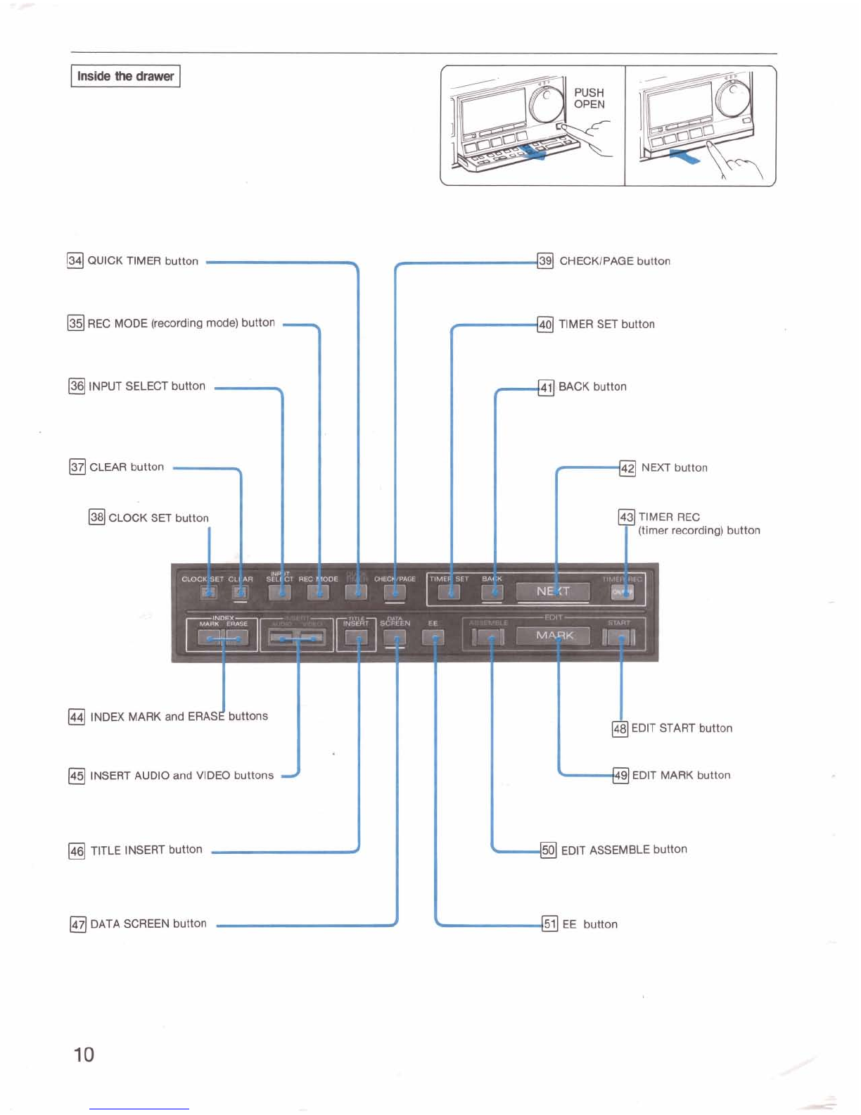
not installthe unit near heat sources such
as
radiatorsor air ducts or in a place subject to direct
sunlight, excessivedust, mechanicalvibration or shock.
The unit isdesigned for operation ina horizontal
position.
Do
not install it inan inclined position.
Keep the unit and cassettetapes away
from
equipment
with strong magnets,
as
for example a microwave
oven
or a large loudspeaker.
Do
not place any heavy object on the unit.
operation
I
When the unit is not in
use,
turn the
power
off to
conserve
energy and to extend its useful life.
Remove and store video cassettes after recordingor
playback.
Store cassettes intheir
cases
and keep them inan
upright positionto prevent intrusion of dust and uneven
winding.
Clean the cabinet, panel and controls with a dry soft cloth,
or a soft cloth lightly moistenedwith a mild detergent
solution.
Do
not use any type of solvent, such as alcohol or benzine,
which might damage the finish.
pmMngI
Do
not throw away the carton and packing materials.
They make
an
ideal container inwhich to transport the
unit. When shippingthe unit to another location, repack it
as illustratedon the carton.
-
-7
PROFESSIONAL-QUALITYEDITING
I
-
The
twin
aylng
erase
heads
eliminatecolor streaks and
blurswhich were conventionally cawed by continuous
recordingsor insert editings.
The
tape
counter
with frame
Wts
displayed on the
monitor screen allows an accurate search of editing
points.
AutomaticassmMeedltlngofupto8~is
possible.
The
CONTROL
T
jack
allows highly accurate preroll
editingby connectinganother SL-HF1000.
OUTSTANDING PICTUREAND SOUND QUALITY
The
6.0
MHz
Super
Heeand
mudng
inlBIsmode
allows recordingof signal information indetail for high
picturequality.
The
DA
(Double
Admuth)
PRO
4
head
reduces noise in
Betascan mode.
Data
smm-The
information of timer programs, editing
points,etc.
are
displayed
on
the monitor
screen
for
easy
presetting
and
checking.
The
rrnnainhg
tape
counter
indicatesthe
length
of
recordingor playback time possible
from
the
actual point
on the
tape
to its
end.
TimeseardrfiAlctknpmvidedtoadvanoeorrewindthe
tape automaticallyto
the
desM
point
by
assignatingthe
time.
Tstle
recordkrg
and
insert
herdkns
provided
to
reoord
or
insert up to
8
titles matedand stored in
memory, as
well
as
the
tape
counter,
date
and
clock dlsplay.
The
mu-
Renlote
Commander
controls dmt
all
functionsof
the
VCR,
and
can
also
be usedwith other
Sony remote
control
VCRs
end TVs.
WHAT
IS
BETA HI-FIRECORDINQ?
Inconventional recording, audio signals
are
recorded
on
the audio track and video signals on the
video
track In
Beta hi-fi recording, audio signals are recordedon the
video track together wlth the video signals using
2
rotary video heads.
The
Beta hi-fiaudio signals
are
frequencymodulated
and recorded on
2
channels,so that you
can
record
a
stereo program with sound quality far superiorto that of
the
conventional audio recording.
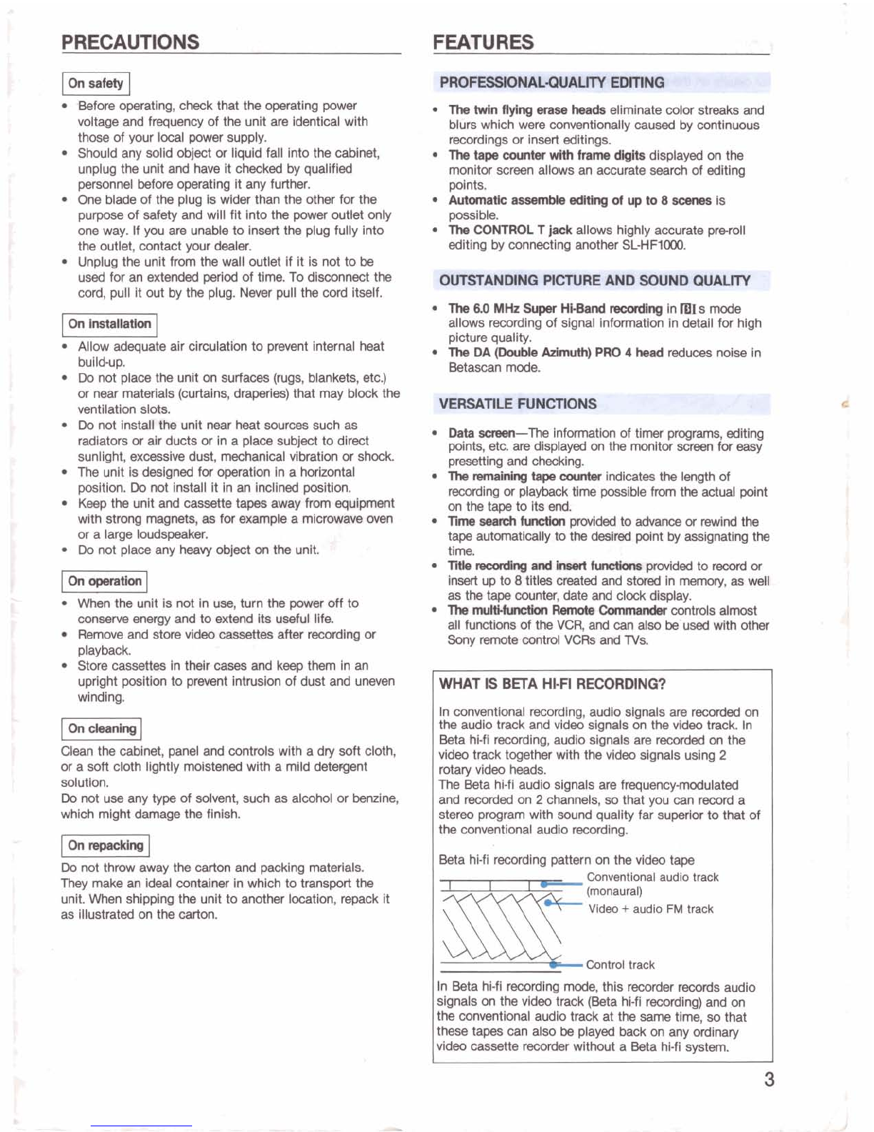
Beta hi-firecording pattern on the video tape
Conventional audio track
-
(monaural)
SllE
Video
+
audio
FM
track
Control track
In Beta hi-firecording
mode,
this
recorder
records audio
signals on the video track (Beta hi-firecording) and on
the conventional audio track at the
same
time, so that
these tapes can also be playedback on any ordinary
video cassette
recorder
without a Beta hl-fi system.

LOCATION AND FUNCTION OF PARTS AND CONTROLS
For details
on
the
use
of each control,
refer
to the pages
indicated in the black circles
(a).
Remotesensor
..-
TVIVTR button and
VTR
indicator
REC LEVEL(recordinglevel) controls
Cassettecompartment
Display
wlndow
(See
page
6.)
Tuning
compartment
f,
Playback indicators
+
EJECT button
-
POWER switch
-
and indicator
I
SuperBeta
indicator
'121
SHUTTLE rina
HEADPHONES
.
jack and LEVEL
control
Beta hi-fl indicator
d
f
a
peak programmeter
#
%
Tape transport buttons
EDIT indicator TAPE RETURN button
COUNTERIREMAIN button COUNTER RESET button

REC LEVEL controls
Q
Adjust the recording level when the BETA HI-FIswitch
isset to ON. Normallykeep these controlsat the center
detent position [5].
&
W
ECT button
Press to eject the cassette.
This buttondoes not function'duringrecording.
SuperBeta indicator
Lightswhen the SUPER BETA switch isset to ON.
When recordingin mIsmode, the indicator lights up to
show mIsrecording, regardless of the position of the
SUPER BETA switch.
HEADPHONESjack and LEVEL control
Connect stereo headphones(witha stereo phone plug)
to the HEADPHONESjack. The volume can be adjusted
with the LEVEL control.
Beta hi-fiindicator
Lightsduring recordingwith the BETA HI-FIswitch at
ON. When playing back a Beta hi-firecorded tape, the
indicator lightsup regardless of the position of the
BETA HI-FIswitch.
Peak program meter
Shows the peak input level of the right and left
channelsduring Beta hi-firecording.
EDIT indicator
Lightswhen the EDIT switch is set to ON.
COUNTERIREMAIN button
0
Press to change the tape counter display to the
approximate recordingor playback time remainingon
the tape.
TVMR buttonand VTR indiator
Press to watch the progam selectedon the recorder so
that the button lights up (VTR mode). To watch a
different
TV
program while recordinganother, press this
buttonagain so that the light goes off.
REC switch
Slide to the right to start recording.
Playback indicators
Indicatethe direction of playback(includingvarious
playback modesand playback pause mode).
4:
Reversedirection
[I
:
Playback pause mode. When this indicator lights,
the JOG dial and SHUlTLE ring can be operated.
b:
Forward direction
SHUTTLE ring
When this ring isturned and held during the playback
pause mode, you can play back the tape at various
speeds, 1110 or 115 normal speed, normalspeed, double
speed, or Betascanspeed. The more it is turned, the
faster the playbackwill be.
JOG dial
Turn to select the channels.
When this dial is turned during the playback pause
mode, the picturewill
be
played back at a speed
according to the speed you are turningthe dial.
This dial is also used for setting date and clock,
presetting timer recordingsand creating titles.
PUSH OPEN button
Press this button to open the drawer. For the controls
insidethe drawer, see page 10.
Channelltimer
+I-
buttons
Press to select the channels, to set the date, clock or
timer program and to create titles. Press
+
to advance
and
-
to reverse.
INDEX button
0
Used for the index scan or index search operation.
ape
transport buttons
44
REW (rewind),
b
PLAY,
w
FF(fast-forward),
STOP,
I
I1H4PAUSEISTILL
P TAPE
RETURN button
In the stop mode, press this button to advance or
rewind the tape to the counter zero point.
COUNTER RESET button
Press to reset the tape counter to "OHOOMOOS'and
"0:00:0090" on the
TV
screen.

0
Automatic editingmode indicator
0
Week
indicator
@
Appears
when the starting time of a timer recordingor
the startlng point of the automatic editing is displayed.
Appears
when
the date isdisplayed.
Q
Indicatesthe editing mode:
ASSEM
(assembly
editing),
A INSERT(audio insert),
V
INSERT
(video
insert),
T
INSERT (titleinsert)
0
Channel number or the
L1
(line
1)/12
(line
2)
input
indicator
O
CATV (cable
TV)
indicator
@
Date, starting time of a timer recording, starting point of
the automaticediting, tape counter
or
remaining time
counter
fj
Appears
during timer setting or checking.
"TIMER REC
will appear when a timer recording is activated.
8
Appears during
recording.
0
Channel of the
stereo
program
0
Input mode indicators
@
EE
mode*
indicator
0
Day-of-the-weekindicator
0
Appears
when the remaining time counter isdisplayed.
49
Timer programnumber for timer-activated recording,
index number for index searchingor scanning, or scene
number for automaticassemble editing
0
Index scan or index search indicator
0
Tape
speed
indicator
Indicatesthat a cassetteis inserted.
0
Appears
when the ending time of a timer recording or
the ending point of the automatic editing
is
displayed.
Q
Appears when the current time is displayed.
0
Dayaf-theweekindicator
Current time, ending time of a timer recording, or ending
point of the automatic editing
0
SAP (Second Audio Program) indicator
*EE
(Electmnic~tcbElectmnics)
mode:
The
input signals (wMch are
not
the signals recorded
on
the
tape)
are
displayed
on
the monitor screen.

Tuning
compartment
WM
AAND
.
M(
IDE
e.
m+w-
rclhblcr
-,z
.
-=L>
a
@
COMMAND MODE decbr
@
To remotely control this
VCR
with the supplied
RemoteCommander, set this
selector
to the
same
positionas that on the Remote Commander.
@m~button@
0
AUTO STEREO
switch
Normally
set
to ON. When the signal is
weak
on
a
particular channel, set to
OFF.
RF UNIT
S&CW
@
@
CAWINOM
(normal)
dectm
@
0
EWE
button
@I
O
STILL
AN
(rmm
picture
adjustnmnt)
control
@

I
~ns~
the
front
panel
1
BETA HI-FI button
MPX FILTER (multiplex filter)/
PCM selector
BLACK SCREEN switch
LINE IN
2
AUDIO jacks LECT(REMAIN) switch
(phone
type)
LlNE IN 2 VIDEO jack OUTLET selector
(Won0 type)
MEjack TRACKING controls
NORMALAUDIO selector
m1
s
SHB
IS
Super Hi-Band) switch
2
k
AUDIO MONITOR
UR
button
l
AUDIO MONITOR BETA
HI-FIIMIXINORMselector

EDlT button
@
Normally keep this buttonat OFF (i.e. the EDlT indicator
is off). When editing a tape onto another recorder, press
the buttonso that the EDlT indicator lights.
SUPER BWA button
@
Normally keep this buttonat ON (i.e. the SuperBeta
indicator lights).
BWA HI-FIbutton
Normally set this buttonto ON for highquality Beta hi-fi
recording (i.e. the Beta hi-fiindicator lights). To record
only inthe conventional system, press the button so
that the indicator goes off.
MPX FlLTERlPCMselector
When making a recording other than regular
TV
recordings, set the selector as follows:
OFF:
For recordingthe sound from a record player or a
compact disc player
ON:
For recording FM radio broadcast programs
(If your FM tuner is provided with an MPX filter, set
this selector to OFF.)
PCM:
For PCM recording and playback
Note
Regardless of the setting of this selector,
TV
programs
are automatically recordedin MPX FILTER ON mode.
BLACK SCREEN switch
@
Normally set to OFF. When recording a title with a
black background, set to ON.
TAPE SELECT (REMAIN) switch
@
Set this switch accordingto the lengthof the tape
being used.
L500:
For L-500cassette tape
L750:
For L-750cassette tape
L830:
For L-830 cassette tape
If this switch is not set appropriately for above listed
tapes, the correct remainingrecordinglplaybacktime
cannot be obtained.
For L-125and L-250cassettes, any positionwill do.
AC
OUTLW
selector
SW (switckll
The AC OUTLET on the rear is
controlled by the front panel POWER switch.
UNSW (unswitched):
The AC OUTLET is not controlled
by the POWER switch and always supplies AC
power.
MICjack
(minitype)
Connect a microphone to record the sound from this
microphoneon the conventional audio track.
SHARPNESScontrol
Use to adjust the sharpness of the picture if necessary.
Normallyset the control at the center detent position.
@
mIs
SHB switch
@
Set to ON to obtain better quality recording in
IBIS
mode.
bEJ
TRACKING
controls
Normally keep these controls at the center detent
position.Turning either of these controls may help clear
possiblestreaks on the screen especially for tapes
recordedon other VCRs.
NORMAL:
For normal and double speed playback.
SLOW:
For slow speed playback by turning the JOG
dial or SHUTTLE ring, x115 and x1110 speed playback,
and freeze picture.
NORMAL
AUDIO
selector
Select the sound to be recordedon the conventional
audio,track. Normally set to MAIN. To record SAP
(Second Audio Program), set to SAP.
AUDIO MONITOR UR button
Select the channel(s) of the Beta hi-fisound to be
monitoredso that the desired indicator appears in the
display window.
STEREO:
To monitor in stereo mode
L:
To monitor the L (left)channel of a stereo program
R:
To monitor the R(right)channel of a stereo program
AUDIO MONITOR BWA HI-FIIMIXINORMselector
Select the sound to be monitored.
BWA HI-FI:
Normallyset to this positionfor Beta hi-fi
sound
MIX:
To monitor the sound recordedon both the video
track in Beta hi-fiand the conventional audio track
NORM:
To monitor the sound recordedon the
conventional audio track only

QUICK TIMER button
3
f
CHECKIPAGE button
REC MODE (recording
mode)
button
-
INPUT SELECT button
*
I-
CLEAR button
-
CLOCK SET button
I
TIMER SET button
1
BACK button
r"
f
NEXT button
(timer recording) button
J
INDEX MARK and ERAS buttons
INSERT AUDIO and VIDEO buttons
TITLE INSERT button
#
DATA SCREEN button
d
9
EDIT MARK button
L
48 EDlT START button
d
50
EDlT ASSEMBLE button
L
button

134)
QLllCK TIMER button
@
Press to start a quick timer recording and then set the
duration of the recording.
REC MODEbutton
@
Press to select the recordingtape speed, mIs,
mII
or
mm.
The playback speed will be set automaticallyregardless
of the setting of this button.
INPUT SELECT button
Pressto select the programto
be
recorded
so
that the
desired input mode indicator appears in the display
window.
TUNER:
For recording
TV
programs
SIMUL:
For recordingthe sound from LlNE IN 1 AUDIO
and the pictureof
TV
program (FM simulcast
recording)
LlNE
L1
(line
1)
For recording signals from LINE
IN
1
VlDEOlPCM and AUDIO
LlNE
L2
(line
2)
For recording signals from LlNE IN
2
VlDEOlAUDlO insidethe front panel
CLEAR button
@
@
Press to clear the timer setting or erase a character
during title creating.
CLOCK SET button
Press to start the setting of the date and current time.
CHECKIPAGEbutton
Press to check the contentsof the preset timer
programsand the starting and ending points of the
automatic assembleediting. This button is also used for
checking the titles created.
TIMER SET button
@
Press to start the setting or resettingof timer programs.
a
BACK button
Press to go back to the item previously set during date,
clock or timer setting, automatic assembleediting or
title creating.
NEXT button
Press to advance to the next itemto be set during date,
clock or timer setting,automatic assemble editing or
title creating.
TIMER REC button
@
Press to activate the timer recording.
INDEX MARK
and
ERASE buttons
@@
Press MARK to mark an index signal at the desired
point on a tape during recording or playback. To erase a
prerecorded index signal, locatethe index signal and
press the ERASE button.
INSERT AUDIO and VIDEO buttons
@
@
Use to "insert" a new recordingonto a portion of a
recorded tape.
AUDIO:
To insert sound on the conventional audio track
VIDEO:
To insert pictureandlor Beta hi-fisound on the
video track
TITLE INSERT button
@@
Use for creating titles and recordingthem. (Title insert
operation)
DATA
SCREEN
button
The channel number,tape operation mode, tape
counter, index function, display for setting and checking
timer recording programsand display for automatic
editing are displayed on the
TV
or monitorscreen
together with a picture.To turn off the display, press
this button. To resumethe display, press it again.
EDlTSTART button
@
@
Press to start the automatic assemble editing or
automatic audiolvideoinsert operation.
EDlT MARK button
@@
Useto mark the starting and ending points for the
automatic assemble editing and automatic audiolvideo
insert operation. Locatethe desired editing point and
press this button.
EDlTASSEMBLE button
@
Press to set the unit to automaticassembleediting
mode.
EE button
Duringtape playback, keep this buttonpressed to
momentarily view and listen to the
TV
program received
by the built-intuner or the program input from the LlNE
IN 1or LlNE
IN
2
jacks. When the button is released,
the playback picturewill returnon the
TV
screen.

I
Rear
1
-
,'-
a
CONTROL T connector
%
f
-@
CONTROL
S
INjack
CONTROL L connector
%
r
pJ
CONTROL
S
OUT
jack
VHFIUHF OUT connector
(F
type)
\
AC OUTLET
VHFlUHF IN connector (F type)
t;,
--
CAMERA REMOTE
J
T
AC
power
cord
IN jack
.
.
h
-
"
'
LlNE OUT VlDEOlPCMjack
(phone
type)
CAMERA REMOTE
d
LINE OUT AUDIO jacks (phono type)
OUT (EDIT) jack
i
:.
LINE IN
1
AUDIO jacks
&
,.
.+.-
>
@
MONITOR OUT VlDEOlPCM jack
(phone
type)
LINE IN
1
VlDEOlPCM jack
J
%
160)
MOlNlTOR OUT AUDIO jacks
(phone
type)
?+
I
La

CONTROL T
jack
(stereomini type)
@@
Connect to the CONTROL T jack of another SLLHF1000
for automatic editing.
CONTROL L
connector
(spin DIN)
@
Connect to the CONTROL L connector of other Sony
productsfor various systematic operations.
Note
Do not connect equipments to the CONTROLT jack
and the CONTROL Ljack simultaneously. This may
cause malfunctionof the equipments.
CONTROL
S
IN
jack
(mini type)
@
Connect to the CONTROL S outputjack of other Sony
productsfor various systematic operations.
CONTROL
S
OUT
jack
(mini type)
@
Connect to the CONTROL S inputjack of other Sony
productsfor automatic assemble editing and other
systematic operations.
AC OUTLET
@
Supplies AC power to video or audio equipment.
CAMERA REMOTE IN
jack
(special mini type)
@
When recording with a video camera, connect the Sony
HVA-220AC adaptor to this jack.
CAMERA REMOTEOUT (EDIT)
jack
(special mini type)
@
Connect to the CAMERA PAUSE or CAMERA PAUSE IN
jack of another Sony VCR for editing.
MONITOR OUT VlDEOlPCM
jack
(phono type)
Connect to the video input of a color monitor,
TV,
another VCR or PCM digital audio processor. The data
for the "Data Screen" display are output from this jack.
MONITOR OUT AUDIO UR
jacks
(phonotype)
Connect to the audio inputsof a color monitor,
TV,
another VCR or stereo system.

I
Remote
Commander
RMT-148
TAPE REMAIN button EE button
COUNTER RESET button m~emotecontrol TVlVTR selector
INDEX MARK and ERASE buttons DATA SCREEN button
Transmitter
1
-
MUTING button
TIME SEARCH button
-
Command mode selector
EJECT button
Number buttons and
ENTER button
INPUT SELECT button
7
411and IIbFRAME
buttons
@variable
speed
playback
-
buttons
TAPE RETURN button
INDEX button
Tape
transport buttons
11
PAUSE, PLAY,
44
REW,
bb
FF, STOP
r
-
VOL (volume)
+I-
buttons
-
POWER
switch
r
TIMERICH (channel)
+I-
buttons
Buttons for timer
mcordlng
QUICK TIMER, TIMER REC ONIOFF,
TIMER SET, CHECKIPAGE, CLEAR
NEXT button
BACK button
REC (record) buttons
2
-
AUDIO, VIDEO and TITLE INSERT
buttons
-
EDIT ASSEMBLE, MARK and
~~,","~~~v~ERfunction button
and indicator
-m
REC MODE (timer recording
mode) button
-SHUTTLE ring
-JOG dial
I
Batterycompartment (rear)
AUTO
PB (autoplay) button JOGSHUTTLE function button
and indicator

Transmitter
Point the transmitter toward the remote sensor on the
VCR.
TIME SEARCH button
0
Press to start setting the time for which you want to
advance or rewindthe tape automatically (time search
operation).
Command mode selector
@
Select the command mode of the equipment you want
to operate with the Commander.To operate this VCR,
set to the same positionas that of the COMMAND
MODE selector insidethe tuning compartment of the
VCR.
Number buttons and ENTER button
@a
Use for selecting channels. After pressingthe digits of
the desired channel one by one, press ENTER.
The number buttonsare also used for settingthe time
for the time search function.
411
and
IIb
FRAME buttons
In freeze picture mode, press
411
to reverse the picture
by one frame, and
IIb
to advancethe picture by one
frame (stop-actionadvance picture). If the button is kept
depressed, the picture moves continuously.These
buttonsare also used to select the direction of
playback. Press
411
for reverse picture, and
IIb
for
forward picture.
Variable speed playback buttons
During playback, press one of these buttons to select
the desired playback speed.
W4
(freeze picture),
~1110,x115, xi,
x2,
SCAN (for
BetaScanpicture)
REC buttons
To start recording, press these buttonssimultaneously.
AUTO
PB
button
Press to play back a tape automatically from the
beginningof the tape after rewinding.
Remote
catrol
TVArrR selector
Normally set to VTR for operating the recorder. To
operate certainSony TVs, set to TV.
REC MODE button
Press to select the recording mode of timer recordings.
This buttononly operates during timer setting.
JOGSHUTTLEfunction button and indicator
Press this buttonwhen using the JOG dial and
SHUTTLE ring for various speed playback.
The other buttonson the Commander have the same
function as the buttonson the VCR with the similar
name or mark.
Some of the buttonson the Commander can be used to
operate certainSony remotecontrol TVs. See page29.
CHANNEUTIMERfunction button and indicator
Press this buttonwhen using the JOG dial for timer
setting, channel selection or title creating.

Before
making
cormections
Turn
off
the
TV.
Do
not
connect
the
AC
power
cord
to a wall outlet until
all the connectionsof the video cassette recorder and
the
TV
have
been completed.
Make connectionsfirmly.
Loose
connections
may
cause
adistorted picture.
ANTENNAICABLE AND
TV
CONNECTION
Disconnect the
TV
antennacables from the
TV
receiver
and connect them to the recorder. Then connect the
recorder and the
TV.
ComMnatlon
VHFlUHF
antenna
Most combination antennas are equippedwith a
UN
band
separator (signal splitter). Take off the separator and
connect the cable directly to the recorder.
Use
the
removed
separator to connect the
recorder
and
the
TV.
VHFlUHF
TV
75ohm
coaxial
cable
*
(supplied)
If you need a separator or acompleteantenna
system,
consult your
Sony
dealer
or
aqualified technician.
*Use
an
optional
RFCB
extension
cable,
8
m
(25
ft)
long, if the
supplied
750hrn
coaxial cable is
not
long
enough.

I
VHF
antenna
I
VHFIUHF
IN
OUT
Antenna
connector
(supplied)
1
Attach
an optional
EAG66
UNband separator to the
VHFIUHF
OUT
connector of the
recorder.
2 Connect the separator to the VHF
and
UHF antenna
terminals of the
TV.

When
both
VHF
and
UHF
antennas
are
connected
1
Attach an optional
EAC66
UN
band
separator (mixer)to
the
VHFIUHF
IN connector of the recorder.
2
Connect the antennasto the
UN
band
separator.
3
Aattach another optional
UN
band
separator tothe
VHFIUHF
OUT
connector of the recorder.
4
Connect itto the
VHF
and
UHF
antenna terminals of
the TV.
When
a
TV
has
a
7-
UHFNHF
ardenna
twnlnal
Easy
connectionof the recorder to the TV can
be
made
with the supplied 75ohm coaxial cable regardlessof the
types
of antenna.
Cau#on
Connections
between
the
recorder
VHFIUHF
OUT
connector and the antenna terminals of a
TV
receiver
should
be
made
only as shown in these Instructions.
Failureto do
so
may result in operation that violates the
regulationsof the
Federal
CommunicationsCommission
regardingthe
use
and operation of
rf
devices.
Never connect the wtput of the
recorder
to an antenna
or make simultaneous (parallel)antenna and recorder
connections at the antenna terminals of your
receiver.
Once the connections explainedabove have
been
made,
the antenna
TV
signals, as well
as
the signal from the
recorder,will
be
fed
to the TV and you can view
TV
programs in the usual way.
Note
Keep
the
VCR
away
from
the TV, if the display or sound
isaffected.

piiiz]
We recommendyou
to
consult your cable company to
make sure that the cable is properly connected.
VHFIUHF
.
IN
OUT
TV
F-typeconnector
CATV
750hm
coaxial cable
750hm
coaxial cable (supplied)
When
a
W
is
not
a
cable
W
compatible
type
Connect the cable
N
channel converter between the
recorderand the
7V
so
that you can watch another cable
N
programwhile recording one cable
TV
program.
VHFIUHF
IN
OUT
CATV
750hm
coaxial cable
75ohm
coaxial cable (supplied)
a
Note
to
CAW
system
installer
in
the
U.U.
This reminder is providedto call the cable
N
system
installer's attentionto Article
8D22
of the
NEC
that
providesquidelines for proper grounding and, in particular,
specifies that the cable ground shall
be
connected to the
grounding system of the building,
as
close to the point of
cable entry as practical.

30Mhrn twin lead
Connect the lead-inwire.
CONNECTING
A
COLOR MONITOR
-
To obtain
a
betterquality picture, connect a color montior,
such as the Sony-ProfeelTrinitron Component
TV.
When a component
TV
is comMned with the speaker
system as Illustrated,you can enjoy tapes recorded with
Beta hi-fistereo.
To usea component
TV
tuner together with the monitor,
makethe same connectionas inthe case
of
the recorder
and the convertional
TV
receiver
described
on pages 16,17
and 18.
For details on the connectionof the
TV
tuner and the
monitor, refer to the instructionmanualof the
TV
tuner.
Component
TV
to MONITOR OUT
Connecting cord(supplied)
Other manuals for SL-HF600
2
Table of contents
Other Sony VCR System manuals

Sony
Sony SLV-SE10 User manual

Sony
Sony Digital Betacam DVW-2000P User manual

Sony
Sony VO-5630 User manual

Sony
Sony SLV-7000KCH User manual

Sony
Sony SVT-S3050P User manual

Sony
Sony HDW-1800 User manual

Sony
Sony MSW-A2000 User manual

Sony
Sony SLV-P58EE User manual

Sony
Sony SLV-L45AR User manual

Sony
Sony SLV-ED10MJ User manual

Sony
Sony SLV-SE70 User manual

Sony
Sony DVCAM DSR-1500 User manual

Sony
Sony SLV-669HF Operator's manual

Sony
Sony SLV-478 User manual

Sony
Sony SL-C6E User manual

Sony
Sony DHR-1000 User manual

Sony
Sony SVX-800 User manual

Sony
Sony SLV-N750 - Video Cassette Recorder Dimensions

Sony
Sony Handycam DCR-TRV320 User manual

Sony
Sony SLV-E180EE User manual