— 3 —
TABLE OF CONTENTS
SERVICE NOTE
1. ERROR CODE INDICATION ··········································· 4
1. GENERAL
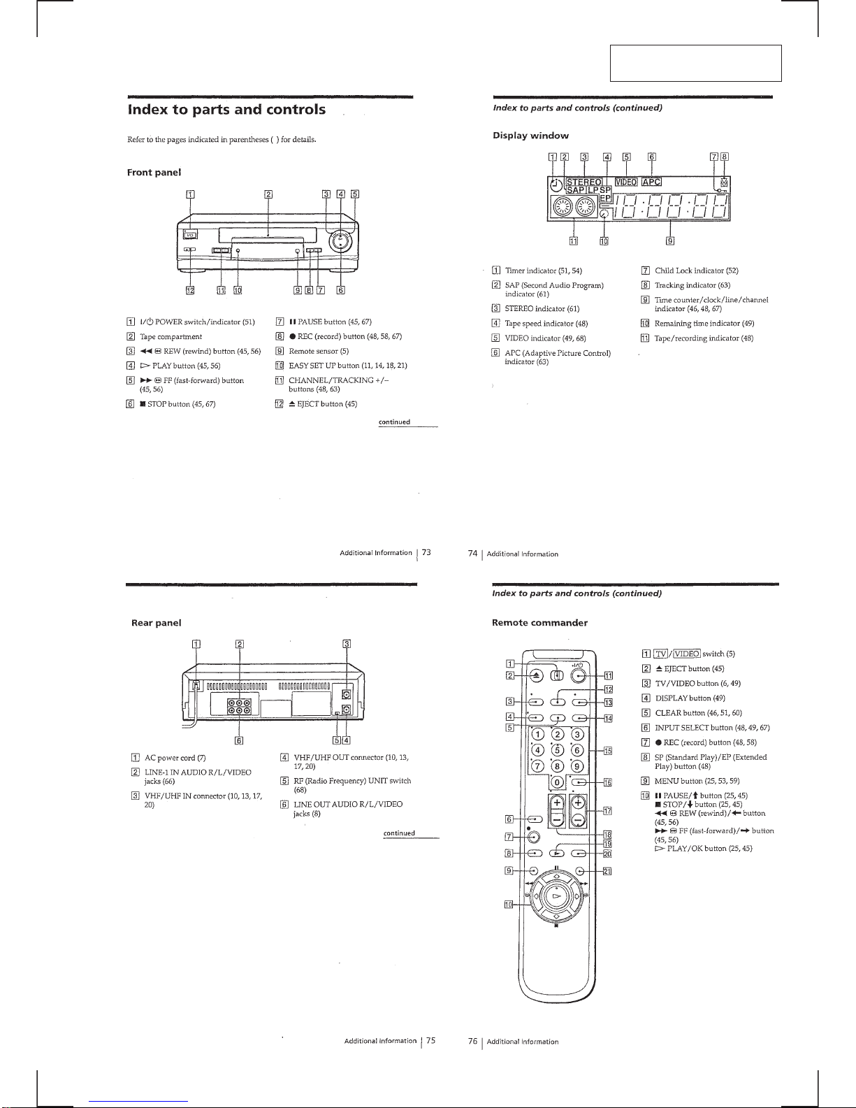
Index to parts and controls ························································1-1
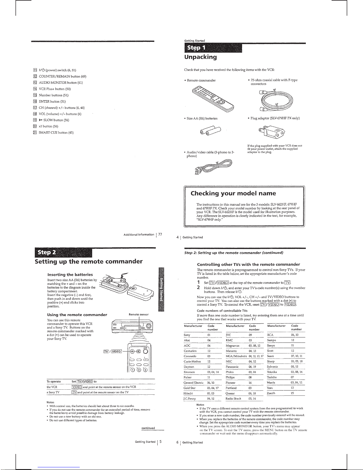
Step 1 Unpacking ······································································1-2
Step 2 Setting up the remote commander··································1-2
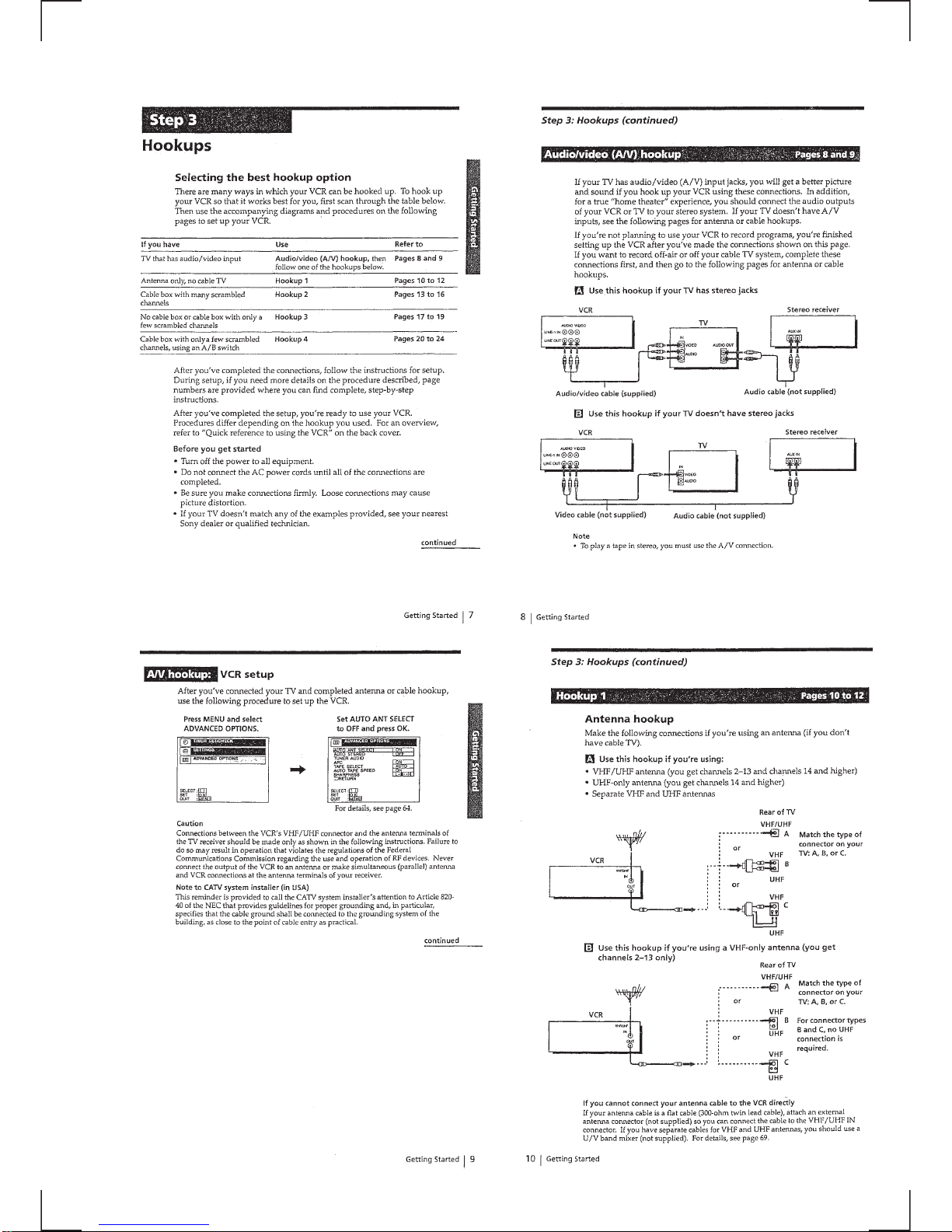
Step 3 Hookups ·········································································1-3
Selecting a language ··································································1-7
Setting the clock ········································································1-7
Presetting channels ····································································1-9
Setting up the VCR Plus+ system············································1-11
Playing a tape ··········································································1-12
Recording TV programs ··························································1-13
Recording TV programs using theVCR Plus+ system ···········1-13
Setting the timer manually ······················································1-14
Playing/searching at various speeds ········································1-15
Setting the recording duration time ·········································1-15
Checking/changing/canceling timer settings ···························1-16
Recording stereo and bilingual programs································1-16
Adjusting the picture ·······························································1-17
Changing menu options ···························································1-17
Editing with another VCR ·······················································1-17
General setup information ·······················································1-18
Troubleshooting·······································································1-18
2. DISASSEMBLY
2-1. UPPER CASE, PANEL BLOCK ASSEMBLY·················· 1
2-2. DS-84 BOARD··································································· 1
2-3. REAR PANEL ···································································· 2
2-4. MA-341 BOARD ······························································· 2
2-5. MECHANISM DECK························································ 3
2-6. INTERNAL VIEWS ··························································· 4
2-7. CIRCUIT BOARDS LOCATION ······································ 5
3. BLOCK DIAGRAMS
3-1. OVERALL BLOCK DIAGRAM ····································3-1
3-2. VIDEO BLOCK DIAGRAM ··········································3-3
3-3. SERVO/SYSTEM CONTROL BLOCK DIAGRAM ·····3-5
3-4. AUDIO/TUNER BLOCK DIAGRAM ···························3-7
3-5. POWER BLOCK DIAGRAM·········································3-9
4. PRINTEDWIRING BOARDS AND
SCHEMATIC DIAGRAMS
4-1. FRAME SCHEMATIC DIAGRAM································4-3
4-2. PRINTED WIRING BOARDS AND SCHEMATIC
DIAGRAMS····································································4-5
• MA-341(1/7) (VIDEO)
SCHEMATIC DIAGRAMS·······················4-5
• MA-341(2/7) (AUDIO)
SCHEMATIC DIAGRAMS·······················4-7
• MA-341(3/7) (SERVO/SYSTEM CONTROL)
SCHEMATIC DIAGRAMS·······················4-9
• MA-341(4/7) (AUDIO PROCESS)
SCHEMATIC DIAGRAMS·····················4-11
• MA-341(5/7) (TUNER)
SCHEMATIC DIAGRAMS·····················4-13
• MA-341(6/7) (MODE CONTROL)
SCHEMATIC DIAGRAMS·····················4-15
• MA-341(7/7) (POWER SUPPLY)
SCHEMATIC DIAGRAMS·····················4-17
• MA-341 (VIDEO, AUDIO, SERVO/SYSTEM
CONTROL, TUNER, POWER SUPPLY)
PRINTED WIRING BOARD ··················4-19
• DS-84 (TAPE OPARATION)
SCHEMATIC DIAGRAMS·····················4-22
• DS-84 (TAPE OPERATION)
PRINTED WIRING BOARD ··················4-22
5. INTERFACE, IC PIN FUNCTION
DESCRIPTION
5-1. SYSTEM CONTROL –
MECHANISM BLOCK INTERFACE
(MA-341 BOARD IC160)···············································5-1
5-2. SYSTEM CONTROL –
SERVO PERIPHERAL CIRCUIT INTERFACE
(MA-341 BOARD IC160)···············································5-1
5-3. SYSTEM CONTROL –
SYSTEM CONTROL PERIPHERAL
CIRCUIT INTERFACE (MA-341 BOARD IC160) ·······5-2
5-4. SYSTEM CONTROL AND RF MODULATOR –
INPUT SELECTION BLOCK INTERFACE
(MA341 BOARD IC160) ················································5-2
5-5. SYSTEM CONTROL – VIDEO/RP BLOCK INTERFACE
(MA-341 BOARD IC160)···············································5-2
5-6. SYSTEM CONTROL – AUDIO BLOCK INTERFACE
(MA-341 BOARD IC160)···············································5-2
5-7. SERVO/SYSTEM CONTROL MICROPROCESSOR
PIN FUNCTIONS (MA-341 BOARD IC160) ················5-3
6. ADJUSTMENTS
6-1 MECHANICAL ADJUSTMENTS ·································6-1
6-2. ELECTRICAL ADJUSTMENTS ···································6-1
1. PREPARATION BEFORE ADJUSTMENT ···················6-1
1-1. Equipment Required························································6-1
1-2. Equipment Connection ····················································6-1
1-3. Set-up of Adjustment ·······················································6-1
1-4. Alignment Tape ·······························································6-1
1-5. Input/Output Levels and Impedance ·······························6-2
1-6. Adjustment Sequence ······················································6-2
2. POWER SUPPLY CHECK ·············································6-2
2-1. Output Voltage Check (MA-341 Board) ·························6-2
3. SERVO SYSTEM CHECK ·············································6-3
3-1. RF Switching Position Adjustment (MA-341 Board) ·····6-3
4. AUDIO SYSTEM ADJUSTMENT·································6-3
4-1. Hi-Fi Audio SystemAdjustment (Hi-Fi model only) ······6-3
4-2. HiFi Switching Position Adjustment (MA-341 Board)···6-4
4-3. Normal Audio System Adjustment ··································6-4
4-3-1.ACE Head Adjustment ····················································6-4
4-3-2.E-E Output Level Check ·················································6-4
4-3-3.Frequency Response Check·············································6-4
5. ADJUSTING PARTS LOCATION DIAGRAM ·············6-6
7. REPAIR PARTS LIST
7-1. EXPLODED VIEWS ······················································7-1
7-1-1.FRONT PANELAND UPPER CASE SECTION ··········7-1
7-1-2.CHASSIS SECTION·······················································7-2
7-1-3.MECHANISM DECK SECTION-1 ·······························7-3
7-1-4.MECHANISM DECK SECTION-2 ·······························7-4
7-1-5.MECHANISM DECK SECTION-3 ·······························7-5
7-2. ELECTRICAL PARTS LIST ··········································7-6