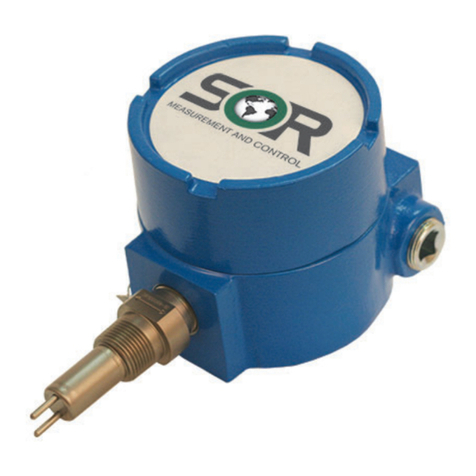
SOR 651 K9 RF Instruction manual

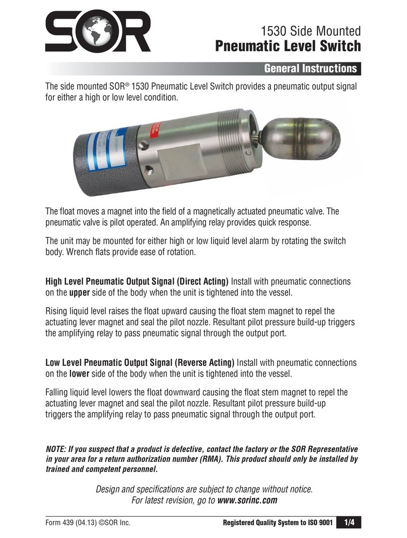
Form 759 (04.16) SOR Inc.
1/16
Remove the housing cover.
Place the instrument on an insulated surface or support
so the sensor does not touch a conductive surface.
Apply 12 to 28VDC, and observe the LED. (See on page 2)
NOTE: When the LED is on, it indicates the output is in the normal state 16-20mA.
Turn the sensitivity adjustment clockwise (up to 25 turns) to increase sensitivity until
the LED goes out.
NOTE: Do not turn the sensitivity adjustment past 25 turns! Damage to the unit could result.
Turn the sensitivity adjustment counterclockwise to decrease sensitivity until the
LED illuminates.
Pre-Installation I/O Test and Calibration
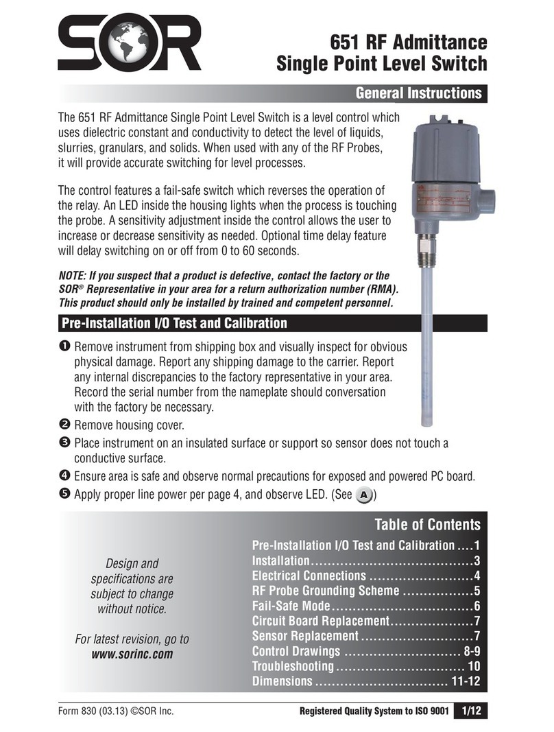
651 K9 RF Admittance
Two Wire Point Level Control
General Instructions
Registered Quality System to ISO 9001
Design and
specifications are
subject to change
without notice.
For latest revision, go to
SORInc.com
Table of Contents
Pre-Installation I/O and Calibration....... 1-2
Installation.......................................3
Electrical Connections .........................4
Post-Installation Calibration ..................4
SOR RF Probe Grounding Screen ............5
Control Drawings ............................ 6-9
Instructions for EMC.......................... 10
Spare Parts .................................... 10
Information for IEC-Listed Product ......... 10
Maintenance and Troubleshooting ......... 11
Dimensions ................................ 12-13
ATEX and IECEx Marking Details ........... 14
Declaration of Conformity ................... 15
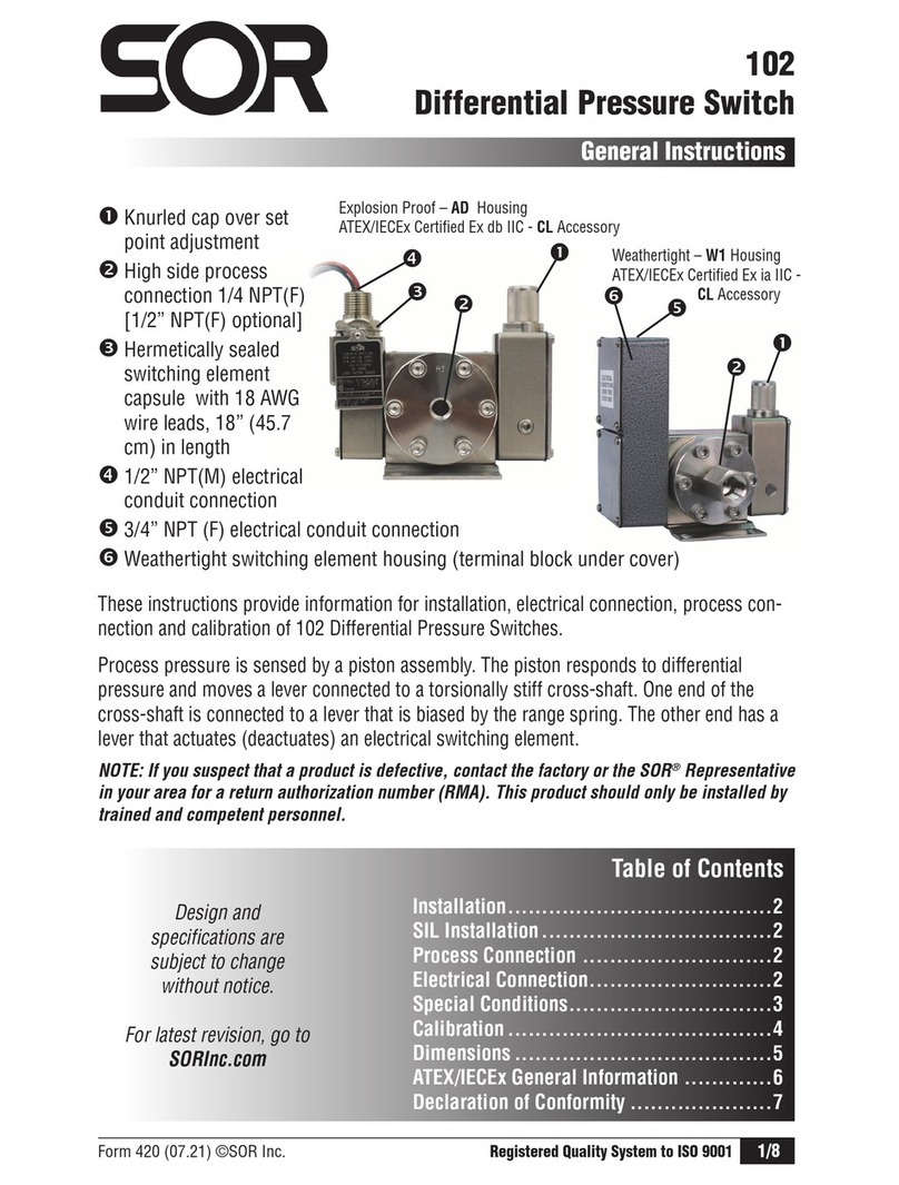
These instructions provide specific information for installation,
electrical connection, calibration and troubleshooting for the
651 K9 RF Admittance Two-Wire Point Level Control.
NOTE: If you suspect that a product is defective, contact the factory
or the SOR®Representative in your area for a return authorization
number.
This product should only be installed by trained and
competent personnel.

2/16
Form 759 (04.16) SOR Inc.
Turn the sensitivity adjustment slowly clockwise until LED goes off, then
counterclockwise until LED goes on to check the null position to verify that the bridge is
balanced. It is desirable to closely bracket the position where the LED came on.
Turn the sensitivity adjustment one turn counterclockwise from the null position. Next,
slowly move a hand toward the probe to touch it. The LED should stay on until the
probe is touched. If it goes out when the hand is near, turn the sensitivity control
counterclockwise so the LED stays on until the hand touches the probe. Usually,
1-2 turns will locate the new null point.
When practical, use a small container of actual process material to calibrate the control.
If the actual process vessel is metal, use a metal container (coffee can, etc.) and ground
it to the instrument housing. If the actual process vessel is an insulator, such as,
fiberglass, use a plastic container.
Immerse the sensor in the process material; the LED should turn off. If not, rotate the
sensitivity adjustment clockwise until the LED goes off.
To detect an interface, such as oil/water or foam/liquid, the lighter material must be in
contact with the sensor, then tuned out. Then adjust the sensitivity to detect the heavier
process material. (See and )
Oil
Water
Terminal Block
(opposite side)
Fail Safe
Switch
Sensitivity
Adjustment
Banana
Plug
LED Ring
Terminal

Form 759 (04.16) SOR Inc.
3/16
Installation
Output Signal
Failsafe Hi Lo
Absence of Process 16-20mA 4-8mA
Presence of Process 4-8mA 16-20mA
Standard conguration is a 3/4” NPT(M) pipe nipple that threads into a 3/4” NPT(F) vessel
nozzle or half coupling. Allow a 4” turn radius (See and ). Sometimes open tanks,
vats, sumps or basins require a locally-made bracket mount similar to that shown in.
(See ).
Optional conguration is a raised face or flat face ANSI flange. See Form 1100 for
selection. (See
g
and )
Orientation. The control can be mounted in any position. Sensitivity is optimized when the
greatest surface area of the sensor is parallel to the process level. (See
p
and )

4/16
Form 759 (04.16) SOR Inc.
Electrical Connections
When the process is adhesive, i.e. it tends to coat the sensor, it may be desirable to mount
it on a 45° angle to reduce product build-up and to increase its effective surface area. (See
and )
Placement and orientation of the sensor in a vessel is frequently determined by available
nozzles. The sensor should be away from fill points to avoid false trips. The insulator
bushing on the sensor should protrude a minimum of 1” from the inner wall of the vessel.
The sensor must not touch any metal, nor should conductive product build-up be allowed
to bridge between the sensor and a grounded metal tank wall.
This product must be installed with an explosion proof breather vent per
Agency requirements and the National Electric Code-Article 501, Section F,
paragraph 3.
Electrical power must be disconnected from explosion proof/intrinsically
safe models before the cover is removed. Failure to do so could result in
severe personal injury or substantial property damage.
Remove the housing cover. Ensure that all wiring conforms to all applicable local and
national electrical codes and install unit(s) according to relevant national and local
safety codes.
Connect the positive loop power wire to the terminal marked “+”.
Connect the negative loop power wire to the terminal marked “-”.
Replace the cover.
Apply power.
Post-Installation Calibration
Units in Hazardous Locations — Prior to calibration, make certain that the
work area is declassied before removing the explosion proof cover to
calibrate the unit. Failure to do so could result in severe personal injury
and/or substantial property damage.
Turn the set-point adjustment to the full clockwise position. The LED should be off
(in Hi Level Fail-safe mode).
Turn the adjustment slowly counter-clockwise until the LED just changes state (on).
Raise the material level until it is above the sensing element. The LED should be off.
Turn the adjustment slowly counter-clockwise until the LED illuminates. Then turn the
adjustment 1/2 turn clockwise (LED off) to complete the calibration.

Form 759 (04.16) SOR Inc.
5/16
SOR RF Probe Grounding Scheme
Critical Grounding Path =
Circuit
Board
Line
Neutral
Ground
Electronics
Housing
Power Supply
Line
Neutral
Ground
Process
Connection
SOR Supplied
Stilling Well
(optional)
Probe Center
Conductive Element
IMPORTANT! Do not
provide separate earth
grounding for the process
connection. This can create
a parallel grounding circuit
that will impair operation
and calibration.
Do not provide separate
earth grounding for the
process connection. This can
create a parallel grounding circuit
that will impair operation and calibration.

6/16
Form 759 (04.16) SOR Inc.
Control Drawing
Drawing 9093008

Form 759 (04.16) SOR Inc.
7/16
Control Drawing
Drawing 9093010

8/16
Form 759 (04.16) SOR Inc.
Control Drawing
Drawing 9093011

Form 759 (04.16) SOR Inc.
9/16
Control Drawing
Drawing 9093009

10/16
Form 759 (04.16) SOR Inc.
Instructions for EMC
651K9
When subjected to an RF Interference, the
651K9 will maintain the +1% accuracy in
all frequency ranges. In order to achieve
the stated accuracy for the 651K9, a
shielded cable, cable gland, shield bead
and the probe should be mounted in a
metallic vessel. SOR recommends using
a shielded cable made of PVC
Insulation around a tinned copper braid
shield (Olflex CY cable or equivalent).
Refer to illustrations for installation of
shield bead onto the probe wire.
Short/Fat Bead
Certificate Number: IECEx BAS 05.0054X, Issue 2
Standards: IEC 60079-0:2011, Ed 6 and IEC 60079-11:2011, Ed 6
Listing: Ex ib IIB Tx Gb (-40°C < Ta < +80°C)
Certificate Number: Baseefa 12ATEX0084X
Standards: IEC 60079-0:2011, Ed 6 and EN60079-11:2012
Condition of Safe Use: This apparatus may not be capable of
withstanding the insulation test required by Clause 6.4.12 of
IEC 60079-11:1999. This must be taken into account when installing the apparatus.
To order a new circuit board assembly, use the following part number:
99-414
Spare Parts
Instructions for IEC-Listed Product
Parameters: Ui = 28V
Ii = 100mA
Pi = 0.75W
Li = 0
Ci = 0
NOTE: Replacement of circuit boards not allowed on agency listed units.

Form 759 (04.16) SOR Inc.
11/16
Sympton/Problem
Possible Cause Corrective Action
LED stays illuminated,
even at maximum
sensitivity setting (full
clockwise 25 turns).
1. Banana plug is loose or
disconnected
2. Probe lead is shorted to
case or ground
3. Faulty sensing circuit
1. Plug banana plug
securely into sensor
jack.
2. Check that the bare end
of the probe is not
touching any metal
part. Clean, repair or
replace the sensor
assembly.
3. Call the factory.
LED stays off, even at
minimum sensitivity
setting (full counter-
clockwise, 25 turns).
No power to the circuit or
excessive loop resistance.
Check the voltage at the
terminal block. It should
be a minimum of 12V.
Device will not detect
process material.
1. Bad circuit switch
2. The oscillator is not
working
Call the factory.
Calibration drifts 1. Sensitivity improperly set
2. Highly conductive
product
3. Heavy conductive
build-up on the sensor
1. Recalibrate according to
Post-Installation
Calibration Instructions
on page 3.
2. Use sheather sensor.
3. Use sheather sensor and
periodically remove
build-up.
Corroded sensor Process material has
chemically attacked sensor
Use sheather sensor to
provide corrosion
resistance.
Eroded or abraded
sensor
Fast flowing or agitated
process has physically
attacked sensor.
Consider other sensor
material or design,
relocating sensor or a
stilling well in liquid
process.
Output current exceeds
23 mA
Bad current switch Call the factory.
Output current is below
3.5 mA
The oscillator is not
working.
Call the factory.
NOTE: Agency certied units, (FM, CSA, IEC) must be returned to SOR for repairs.
Troubleshooting

12/16
Form 759 (04.16) SOR Inc.
Process Connection
Dim B Dim C
Cable Probe All Other
Probes Cable Probe All Other
Probes
3/4” NPT(M) 87.8
3.46
94.1
3.71
256.0
10.08
262.4
10.33
1, 1-1/2, & 2” NPT(M) 99.7
3.92
97.3
3.83
268.0
10.56
265.6
10.46
Flanged 158.5
6.24
158.5
6.24
326.8
12.87
326.8
12.87
Stilling Well N/A 120.0
4.72 N/A 288.3
11.35
Dimensions - K Housing Conguration (Explosion Proof Integral)
B
C
96.0
3.78
116.7
4.59
A LENGTH
(PER MODEL NUMBER)
19.1
0.75
(INACTIVE SHEATH ONLY)
D
INACTIVE SHEATH LENGTH
(PER MODEL NUMBER)
3/4 NPTF
ELECTRICAL CONNECTION
PROCESS
CONNECTION
SEE TABLE
1
1
Linear = mm/inches
Drawing 0390654
Dimensions are for reference only.
Contact the factory for certified drawings
for a particular model number.
SENSOR STYLE D
BARE 12.7
0.50
SHEATH 15.9
0.63
BARE WITH
STILLING WELL
26.7
1.05
SHEATH WITH
STILLING WELL
26.7
1.05
CABLE 7.90
0.31
INACTIVE SHEATH 15.9
0.63
NOTES:
1. DIMENSION APPROXIMATE AND BASED
ON A FIVE THREAD ENGAGEMENT.
1

Form 759 (04.16) SOR Inc.
13/16
54.0
2.13
31.8
1.25
27.0
1.06
SEE DETAIL A
U
AL CABLE PROBE DETAIL
3/4-16 UNF-
Dimensions - K Housing Conguration (Explosion Proof Integral)
Dual Rigid Probe Detail
50.8
2.00
31.8
1.25 28.4
1.12
SEE DETAIL A
DUAL CABLE PROBE DETAIL
DUAL RIGID PROBE DETAIL
MINIMUM CLEARANCE HOLE
FOR INSTALLATION
54.9
2.16
36.5
1.44
22.2
0.88
D
3/4-16 UNF-2B X 11.1
0.44
Linear = mm/inches
Drawing 0390654
Linear = mm/inches
Drawing 0390654
Dual Cable Probe Detail
Dimensions are for
reference only.
Contact the factory
for certified drawings
for a particular model
number.

14/16
Form 759 (04.16) SOR Inc.
Sample Nameplates
Location of Product
Model Identification
Location of
Serial Number
(First Two Numbers
Indicate Year of
Manufacture)
General Information for ATEX Certied Models
Location of ATEX
Listing Information
Drawing 8924119
Drawing 0720527
Manufacturer’s
Registered
Trademark
Manufacturer’s
Registered
Trademark

Form 759 (04.16) SOR Inc.
15/16
Declaration of Conformity
For ATEX Certied Models
Form 1384 (04.16) ©SOR Inc.
Product
Manufacturer
Date of Issue
We declare that the above
products conform to
the following specifications
and directives
Carries the marking
Reference document
ATEX Notified Body
Person responsible
2 Wire RF Admittance Transmitter Model 651
SOR Inc.
14685 West 105
th
Street
Lenexa, Kansas 66215-2003
United States of America
April 20, 2016
ATEX Directive (2014/34/EU) Equipment Intended for
use in Potentially Explosive Atmospheres
IEC 60079-0: 2011 IEC 60079-11: 2011
EN 60079-11: 2012
II 2G Ex ib IIB T4 Gb
(-40°C Ta +80°C)
EC-Type Examination Certificate
Baseefa 12ATEX0084X
IECEx BAS 05.0054X Issued August 16, 2005
Baseefa Ltd. (Notified Body No. 1180)
Rockhead Business Park, Staden Lane,
Buxton, Derbyshire SK17 9RZ
United Kingdom
Baseefa Customer Reference No. 1021
Michael J. Bequette (VP of Engineering)
14685 West 105th Street, Lenexa, KS 66215-2003
s53!s&!8
Engineered to Order with Off-the-Shelf Speed
EC Declaration
of Conformity
Michael J. Bequette

16/16
Form 759 (04.16) SOR Inc.
14685 West 105th Street, Lenexa, KS 66215
913-888-2630
800-676-6794 USA
Fax 913-888-0767
Registered Quality System to ISO 9001
SORInc.com
Table of contents
Other SOR Switch manuals
