SOR 1550 Instruction manual

Form 865 (04.16) ©SOR Inc.
1/8
Do not exceed catalog stated electrical ratings. Improper current input to
switch will cause permanent damage to contacts.
Electrical Connection
The SOR
®
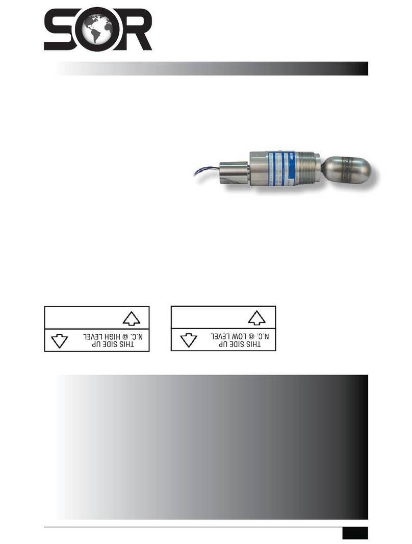
1550 Electric Level Switch mounts into the top of a vessel.
Electric switching action is provided by the float moving a magnet into the
field of a hermetically sealed reed switch.
NOTE: If you suspect that a product is defective, contact the factory or the
SOR Representative in your area for a return authorization number (RMA).
This product should only be installed by trained and competent personnel.
1550 Top Mounted
Level Switch
General Instructions
Registered Quality System to ISO 9001
Design and
specifications are
subject to change
without notice.
For latest revision, go to
www.SORInc.com
Table of Contents
Electrical Connections ........................ 1
SIL Installation ................................. 2
Wiring ........................................... 2
Float Attachment............................... 3
Special Conditions............................. 3
Dimensions ..................................... 4
ATEX and IECEx Marking Details ............ 4
Declaration of Conformity .................... 6
Troubleshooting ................................ 7
Replacement Parts ............................ 7
Before Installing the Level Switch
Inspect the unit for any shipment damage.
Check for mechanical clearance of the float. Float must move freely
without binding throughout its stroke.
Use an acceptable thread compound when installing unit to ensure
a leak-free fit and avoid thread galling.
Electrical connection is free wire leads with a 1/2” NPT(F) conduit
connection. Use two wrenches - one to hold hex conduit connection,
the other to tighten conduit fitting. Switching element is a hermetically
sealed reed switch.
Wiring schematics shown on page 2.
Ensure that all wiring conforms to all applicable local and national electrical
codes and install unit(s) according to relevant national and local safety codes.
al
t
he
.
.
ral
Instructions
rica
al

2/8
Form 865 (04.16) ©SOR Inc.
NC 2
NO 2
NC 1
NO 1
5
6
4
3
7
2
1
8
Switch Capsule
Black Lead
White Lead
C2
C1
Power
Supply Relay Coil
SPST Reed
Switch Capsule
SPDT Reed
Switch Capsule
Common Black Lead
Common Black Lead Normally Open Blue Lead
Normally Closed White Lead
Normally Open White Lead
For Type 1550 Level Switches equipped with DPDT relays, a wiring schematic and pin
position schematic is shown below. When the 1550 is actuated, the coil will energize and
“make” both NO1 and NO2 while it will “break” NC1 and NC2. This provides a DPDT circuit.
Wiring for DPDT Relay
DPDT Relay Schematic
3
NO1
2187
C2C1
4
NC1 5
NC2 6
NO2
Wiring for SPST and SPDT Switch Operation
Safety Integrity Level (SIL) Installation Requirements
The SOR pressure switches have been evaluated as Type-A safety related hardware.
To meet the necessary installation requirements for the SIL system, the following
information must be utilized:
Proof Test Interval shall be one year.
Units may only be installed for use in Low Demand Mode.
Products have a HFT (Hardware Fault Tolerance) of 0, and were evaluated in a
1oo1 (one out of one) configuration. Form 1538 (03.12) ©2012 SOR Inc.

Form 865 (04.16) ©SOR Inc.
3/8
Linear = mm/inches
Drawing 0390747
APPLY TWO DROPS
LOCTITE 271 INSIDE
THREADED HOLE
OF FLOAT
FLOAT
SET SCREW
Place two drops of Loctite 271
inside the threaded hole of the float.
Thread the float onto the set
screw and hand-tighten.
NOTE: Do not remove the set screw as
it secures the pivot arm to the shaft.
NOTE: Do not remove the stem guide
as it may cause damage to the unit.
Float Attachment (Series 1500 with Flange)
Special Conditions for Safe Use
This apparatus may have a combined nameplate which carries multiple approvals
(intrinsically safe and flameproof). The equipment should be marked as to which protection
method it is installed as and shall not be changed or utilized in any other means than was
originally marked by the end user.
When marked and installed as Ex i equipment, the permanently attached leads must be
suitably protected against mechanical damage and terminated in a suitable junction box or
terminal facility having a degree of protection at least IP20.
When marked and installed as Ex d equipment, the permanently attached leads must be
suitably protected against mechanical damage and terminated in a suitable junction box or
terminal facility.

4/8
Form 865 (04.16) ©SOR Inc.
Dimensions
Linear = mm/inches
Drawing 0390428
Linear = mm/inches
Drawing 0390764
With CK Accessory – ATEX and IECEx dual approved:
152.4
6.00
177.8
7.00
177.8
7.00
* L
* L
13.5
0.53
22.2 WRENCH FLATS
0.87
88.9
3.50
P
TITLE
DI
M
LEV
EO
SC
A
*DISTA
N
L : ____
_
STEM GUIDE
STEM
FLOAT
WIRE LEADS 457.2
18.00 MIN LENGTH
COLOR CODED AND MARKED
44.5 WRENCH FLATS
1.75
1-1/2" NPTM PROCESS CONNECTION
1/2" NPTF
ELECTRICAL
CONNECTION
FLANGE PROCESS CONNECTION
_________" ___________# RF FLANGE
AS SPECIFIED ON SALES ORDER
I
L = DISTANCE TO
ACTUATING LEVEL
L = DISTANCE TO
ACTUATING LEVEL
13.5
0.53
44.5
1.75
W
RENCH
FLAT
144.5
5.69
1144.5
5.69
1
P
R
TITLE
DI
M
FLA
N
EO
N
SCA
L
STEM GUIDE
STEM
FLOAT
PROCESS
CONNECTION
1-1/2 NPTM STD
2 NPTM OPT
COLOR CODED
AND MARKED
WIRE LEADS
457.2
18.00 MIN LENGTH
PROCESS
CONNECTION
FLANGE
11
13.5
0.53
44.5
1.75
WRENCH
FLAT
ELECTRICAL
CONNECTION
1/2 NPTF STD
3/4 NPTF OPT
COLOR CODED
AND MARKED
WIRE LEADS
457.2
18 00 MIN LEN
Dimensions are for
reference only. Contact
the factory
for certified drawings
for a particular model
number.

Form 865 (04.16) ©SOR Inc.
5/8
ATEX and IECEx Marking Details
For ATEX and IECEx Certied Models
Standards Assessed To
ATEX Certification: EN 60079-0: 2009 & EN 60079-11: 2007
EN 60079-0: 2012, EN 60079-1: 2007,
EN 60079-11: 2012 & EN 60079-26: 2007
IECEx Certification: IEC 60079-0: 2011, IEC 60079-1: 2007-04,
IEC 60079-11: 2011 & IEC 60079-25: 2010-02
IEC 60079-0: 2004 & IEC 60079-11: 1999
ATEX Listing
Information
Drawing 0720554
Manufacturer’s
Registered Trademark
Product Type
Identification
Product Model Identification

6/8
Form 865 (04.16) ©SOR Inc.
Declaration of Conformity
For ATEX Certied Models
EC Declaration
of Conformity
14685 West 105th Street, Lenexa, KS 66215-2003
s53!s&!8
Engineered to Order with Off-the-Shelf Speed
Form 1385 (04.16) SOR Inc.
Product
Manufacturer
Date of Issue
We declare that the above
products conform to
the following specifications
and directives
Carries the Marking
Reference Documents
ATEX Notified Body
Person Responsible
Type 1500 Electric Switches
SOR Inc., 14685 West 105
th
Street, Lenexa, Kansas 66215-2003
5NITED3TATESOF!MERICA
April 20, 2016
!4%8$IRECTIVE%5%QUIPMENT)NTENDEDFORUSE
IN0OTENTIALLY%XPLOSIVE!TMOSPHERES
%.%.
)%#)%#
%.%.
%.%.
)%#)%#
)%#)%#
!4%8-ARKING )%#%X-ARKING
II 1 G Ex ia IIC Ga Ex ia IIC Ga
4²#d4Ad²#OR 4²#d4Ad²#OR
4²#4A ²# 4²#4A ²#
II 2 G Ex d IIC Ga/Gb Ex d IIC Ga/Gb
4²#d4Ad²#OR 4²#d4Ad²#OR
4²#4A²# 4²#4A ²#
EC-Type Examination Certificate
Baseefa06ATEX0271X, IECEx BAS06.0063X
)SSUED*ANUARY
Baseefa13ATEX0056X, IECEx BAS13.0035X
)SSUED*ULY
SGS Baseefa Ltd..OTIlED"ODY.O
2OCKHEAD"USINESS0ARK3TADEN,ANE
"UXTON$ERBYSHIRE3+2:5NITED+INGDOM
"ASEEFA#USTOMER2EFERENCE.O
-ICHAEL*"EQUETTE60OF%NGINEERING
-ICHAEL*"EQUETTE

Form 865 (04.16) ©SOR Inc.
7/8
Troubleshooting
Symptom Probable Cause
Float in actuated position but no
output signal.
a. No power supply.
b. Switch damaged. (Replace.)
Float in de-actuated positon but
still receiving an output signal.
a. Switch damaged. (Replace.)
Liquid in vessel at the actuation
level but unit does not respond.
a. Leaky or collapsed float. (Replace.)
b. Liquid specific gravity too low.
c. Float stem bound up or dirty. (Clean.)
d. Float travel is obstructed. Verify float
can move freely and is not obstructed
when installed.
Part Number Description
3130-091 W9 - SPST Hermetically Sealed Switch Capsule
3130-245 W1 - SPDT Hermetically Sealed Switch Capsule
3130-259
W1 - SPDT Switch/Conduit Connection Assembly (CK Option Only)
3130-107 L9 - SPST Hermetically Sealed Switch Capsule
3130-244 L1 - SPDT Hermetically Sealed Switch Capsule
3130-260 L1 - SPDT Switch/Conduit Connection Assembly (CK Option Only)
3101-122 316SS Float. (Consult factory for other materials.)
3130-396 Actuator Arm Replacement Kit
Replacement Parts

8/8
Form 865 (04.16) ©SOR Inc.
14685 West 105th Street, Lenexa, KS 66215
913-888-2630
800-676-6794 USA
Fax 913-888-0767
Registered Quality System to ISO 9001
SORInc.com
Table of contents
Other SOR Switch manuals
