SOR 1710 Instruction manual

Form 916 (06.18) ©SOR Inc.
1/8
1710 Side Mounted
Level Switch
General Instructions
Registered Quality System to ISO 9001
Design and
specifications are
subject to change
without notice.
For latest revision, go to
SORInc.com
Table of Contents
Physical Installation............................2
Electrical Installation ..........................3
SIL Installation Requirements ................3
Dimensions ......................................4
Replacement Switch Assemblies ............4
ATEX Information ...............................5
Declaration of Conformity .....................7
Maintenance.....................................8
Troubleshooting .................................8
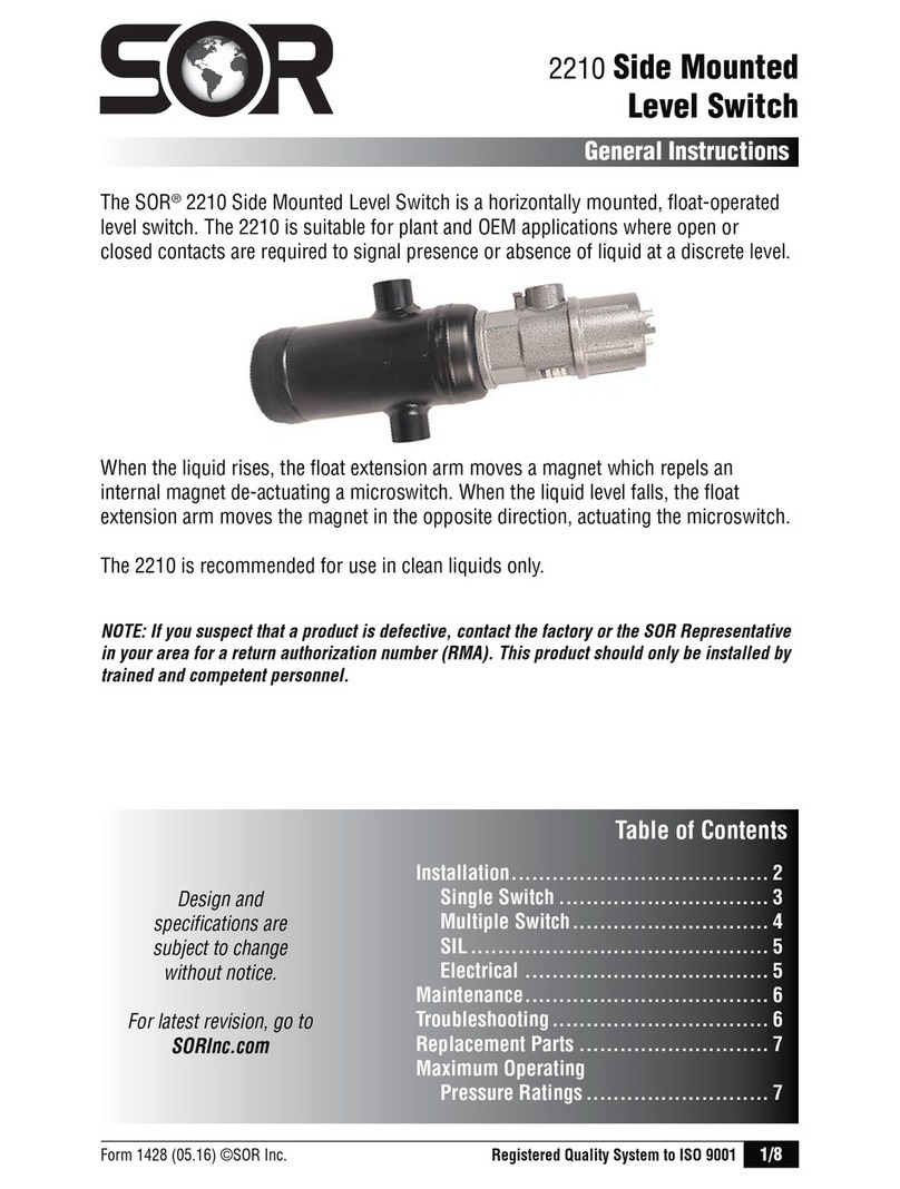
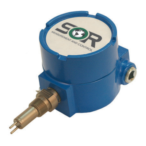
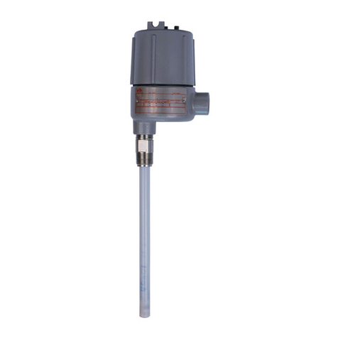
The SOR®1710 Side Mounted Level Switch is a horizontally mounted, float-operated
level switch. The 1710 is suitable for plant and OEM applications where open or closed
contacts are required to signal presence or absence of liquid at a discrete level.
When the liquid rises, the float extension arm moves a magnet which repels an internal
magnet de-actuating a microswitch. When the liquid level falls, the float extension arm
moves the magnet in the opposite direction, actuating the microswitch.
The 1710 is recommended for use in clean liquids only.
NOTE: If you suspect that a product is defective, contact the factory or the SOR Representative
in your area for a return authorization number (RMA). This product should only be installed by
trained and competent personnel.

2/8
Form 916 (06.18) ©SOR Inc.
Physical Installation
The 1710 must be mounted so that the centerline is within 3º of horizontal. The
conduit connection centerline must be within 3° of vertical and the nameplate at 12
o’clock. Switch actuation cannot be reversed by rotating the unit 180°.
Pipe support hangers or stands should be used where necessary.
All isolation valves must be fully open during service, as restricted valves may
cause erroneous level switching.
Remember external chamber piping should be short, straight and unrestricted.
Pipe must be of a diameter equal to or greater than the process connection
diameter.
Valves and other equipment between the chamber and process must be of the same
diameter or larger than the process connection diameter to allow adequate liquid
flow into the chamber.
Installation shall be carried out by suitably-trained personnel in accordance with the
applicable code of practice e.g. EN 60079-14.
Not following these installation instructions, including pipe and valve
diameter and pipe lengths can affect operation of the switch, including
differential.

Form 916 (06.18) ©SOR Inc.
3/8
Electrical Installation
nRemove the end cover to gain acess to the switch mechanism and terminal block.
oFeed the switching wires into the housing through the electrical connection. Wire
to the terminal block(s) as shown in . Select wires which are compatible with
temperature and electrical load required by the application. Keep wire length as
short as possible to prevent damage when cover is installed.
p
Connect the ground wire to the green ground screw located on the outside of the housing.
qReplace the switch cover. Ensure switch cover is screwed on all the way.
rHousing becomes very hot during regular use, high temp. conduit connections are
necessary.
sTest the switch action by varying the liquid level in the chamber or tank.
The cover can become
extremely hot during
operation. Use adequate
protection to prevent
severe personal injury.
LIQUID
LEVEL
LOW
LIQUID
LEVEL
HIGH
SPDT DPDT
WIRING CONTINUITY
1
2
3
4
5
6
SPDT DPDT
Safety Integrity Level (SIL) Installation Requirements
The SOR pressure switches have been evaluated as Type-A safety related hardware.
To meet the necessary installation requirements for the SIL system, the following
information must be utilized:
Proof Test Interval shall be one year.
Units may only be installed for use in Low Demand Mode.
Products have a HFT (Hardware Fault Tolerance) of 0, and were evaluated in a
1oo1 (one out of one) configuration. Form 1538 (03.12) ©2012 SOR Inc.

4/8
Form 916 (06.18) ©SOR Inc.
Dimensions
Linear = mm/inches
Drawing 0390777
Dimensions are for reference only. Contact the factory
for certified drawings for a particular model number.
423.2±14.2
16.66±0.56
423.2±14.2
16.66±0.56
COUNTERBALANCE
FLOAT
Designator
Replacement switch assemblies include: bracket, terminal block, magnet, and
microswitch(es). Choose the appropriate switch mechanism and order it using the
part number shown.
The switch designator is located in the empty position of the sample model number below:
1710A - G2A - C - - H1
Replacement Switch Assemblies
Part Number Description (see back page for specifications)
A 1
380801 SPDT
General Purpose
A 4
380310 DPDT
S 1
380381 SPDT
Hermetically Sealed,
Gold Contacts
S 4
380570 DPDT
NOTES:
112.8
1. ADD MINIMUM CLEARANCE
4.44
REQUIRED TO REMOVE HOUSING COVER
1
Components to be incorporated into or used as replacement parts of the equipment
shall be fitted by suitably-trained personnel in accordance with the manufacturer’s
documentation (or inform of contracting manufacturer or their stockist or specify no
replaceable component parts).
93.7
3.69
10-32 EXTERNAL
GROUND SCREW
ELECTRICAL CONN
1 INCH NPTF
1
112.6
4.43
104.2±11.1
4.10±0.44
79.6
3.13
2 IN NPT(M)
PROCESS CONNECTION

Form 916 (06.18) ©SOR Inc.
5/8
ATEX Information
For ATEX Certied Models
Product Type IdentificationATEX Listing InformationManufacturer’s
Registered Trademark
Location of Product Model
Identification Drawing 0720558
The certification of this equipment relies upon the following material used in its
construction:
ENCLOSURE MATERIAL:
ALUMINUM 356.0-T6 (COVER AND HOUSING, ASTM B 108)
O-RING COMPOUND: SILICONE, PARKED COMPOUND S1224
The equipment may be used with flammable gases and vapours with apparatus groups
IIC or IIB + Hydrogen (see product nameplate) and with temperature class T5 in the
ambient temperature range -40ºC to +80ºC.
The equipment is only certified for use in ambient temperatures in the range -40ºC to
+80ºC and should not be used outside this range.

6/8
Form 916 (06.18) ©SOR Inc.
Special Conditions for Safe Use
To minimize the risk of electrostatic discharge, clean only with a damp cloth.
When the equipment is installed particular precautions must be taken to ensure the
process temperature does not affect the ambient temperature range -40°C to 80°C
of the overall liquid level control switch assembly.
If the equipment is likely to come into contact with aggressive substances, than it
is the responsibility of the end user to take suitable precautions that prevent it from
being adversely affected, thus ensuring that the type of protection provided by the
equipment is not compromised. If in doubt contact the manufacturer.
Flamepath joints are not intended to be repaired.
Process
Connection
Description
Pressure at Listed Temperature in psig (bar)
100°F
(38°C)
200°F
(93°C)
300°F
(149°C)
400°F
(204°C)
500°F
(260°C)
600°F
(316°C)
700°F
(371°C)
G2A 2” NPT(M) 1500
(103)
1500
(103)
1500
(103)
1500
(103)
1500
(103)
1500
(103)
1500
(103)
G3C
3” 150#
RF Flange
(316SS)
275
(19)
235
(16)
215
(15)
195
(13)
170
(12)
140
(10)
110
(8)
G3D
3” 300#
RF Flange
(316SS)
720
(50)
620
(42)
560
(39)
515
(36)
480
(33)
450
(31)
435
(30)
G4C
4” 150#
RF Flange
(316SS)
275
(19)
235
(16)
215
(15)
195
(13)
170
(12)
140
(10)
110
(8)
G4D
4” 300#
RF Flange
(316SS)
720
(50)
620
(42)
560
(39)
515
(36)
480
(33)
450
(31)
430
(30)
Maximum Operating Pressure Ratings
Chamber
Designator
Description
Pressure at Listed Temperature in psig (bar)
100°F
(38°C)
200°F
(93°C)
300°F
(149°C)
400°F
(204°C)
500°F
(260°C)
600°F
(316°C)
700°F
(371°C)
EE 4” S40
Carbon Steel
1500
(103)
1500
(103)
1397
(96)
1282
(88)
1196
(82)
1129
(78)
1081
(75)
EG 4” S40
316/316L SS
1435
(99)
1435
(99)
1435
(99)
1435
(99)
1435
(99)
1435
(99)
1378
(95)
With External Chamber
Electrical and Pressure Paramaters
Switch Rating
A 6A, 125/250 VAC
S 1/2A, 28 VDC

Form 916 (06.18) ©SOR Inc.
7/8
Declaration of Conformity
For ATEX Certied Models
Form 1386 (12.17) ©SOR Inc.
Product
Manufacturer
Date of Issue
We declare that the above
products conform to
the following specifications
and directives
Carries the marking
Reference document
ATEX Notified Body
Person responsible
Michael J. Bequette
14685 West 105th Street, Lenexa, KS 66215-2003
s53!s&!8
Engineered to Order with Off-the-Shelf Speed
EC Declaration
of Conformity
1710 Side Mounted Level Switch
SOR Inc.
14685 West 105th Street
Lenexa, Kansas 66215-2003
5NITED3TATESOF!MERICA
December 4, 2017
!4%8$IRECTIVE%5%QUIPMENT)NTENDEDFORUSEIN
0OTENTIALLY%XPLOSIVE!TMOSPHERES
%.!)%#
%. )%#
%. )%#
Ex db IIC T5 Gb; Ex tb IIIC T90°C Db;
(Nonchambered); Ex d IIB + H2 T5 Gb;
Ex tb IIIC T90°C Db (Chambered)
Ta=-40°C <Tamb <+80°C
EC-Type Examination Certificate
SIRA 13ATEX1306X
IECEx CSA 13.0024X
)SSUED-ARCH
Baseefa Ltd..OTIlED"ODY.O
2OCKHEAD"USINESS0ARK3TADEN,ANE
"UXTON$ERBYSHIRE3+2:
5NITED+INGDOM
"ASEEFA#USTOMER2EFERENCE.O
-ICHAEL*"EQUETTE60OF%NGINEERING

8/8
Form 916 (06.18) ©SOR Inc.
14685 West 105th Street, Lenexa, KS 66215
913-888-2630
800-676-6794 USA
Fax 913-888-0767
Registered Quality System to ISO 9001
Printed in USA SORInc.com
Maintenance
Troubleshooting
Keep the cover tightly secured to the housing.
Prevent moisture or dirt from entering the housing when the cover is off.
Check all screw terminal connections periodically. Vibration may loosen the screw terminals.
Clean the float and counterweight mechanism periodically to assure continued free movement.
Make no adjustments to the switch mechanism. It is factory calibrated for optimum
performance.
Apply petroleum jelly or anti-seize compounds to cover threads periodically to
prevent seizing.
Inspection and maintenance of this equipment shall be carried out by suitibly-trained
personnel in accordance with the applicable code of practice e.g. EN 60079-17.
Repair of this equipment (as applicable) shall be carried out by suitably-trained
personnel in accordance with the applicable code of practice e.g. EN 60079-19.
Do not remove the cover when the unit is energized.
Symptom Probable Cause
The float is in the actuated
position but the switch
does not actuate.
a. The terminal block is wired incorrectly. Check wiring.
b. The unit is installed upside-down. Rotate housing so
that the nameplate faces up.
c. The switch is damaged. Contact the factory.
The float is in the de-actuated position
but the switch remains actuated.
a. The terminal block is wired incorrectly. Check wiring.
b. The switch is damaged. Contact the factory.
The control will not function when
installed but operates when
removed from process connection.
a. Float travel is inadequate. Check for internal
vessel obstructions. See Mounting Requirements.
Liquid is in the vessel at the actuation
level but the unit does not respond.
a. The float pivot pin is bound up or dirty. Clean the
float pivot pin.
b. The unit is installed upside-down. Rotate housing
so that the nameplate faces up.
c. The specific gravity of the liquid is not sufficient
to lift the float.
d.
The float is leaky or collapsed. Contact the factory.
Table of contents
Other SOR Switch manuals
