Sorel HE-Check User manual
Manual
en
Function
Operation
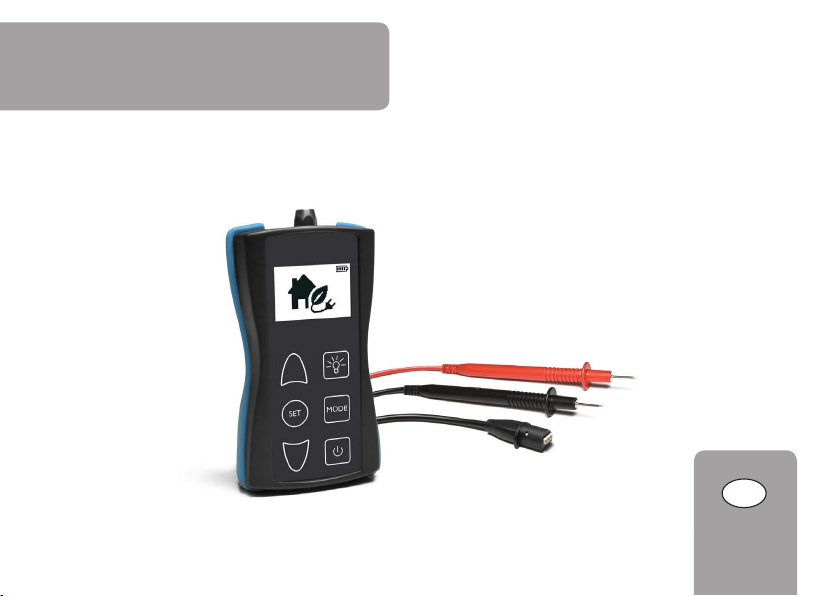
HE-Check
Testing device for PWM and 0-10V signals

en
10
Safety advice
Please pay attention to the following safety advice in order
to avoid danger and damage to people and property.
Description of symbols
ATTENTION! Warnings are indicated with a warning
triangle!
ÎThey contain information on how
to avoid the danger described.
Signal words describe the danger that may occur, when it
is not avoided.
• ATTENTION means that damage to the appliance can
occur.
ÎArrows indicate instruction steps that should be car-
ried out.
Note
Notes are indicated with an information symbol.
Thank you for buying this product.
Please read this manual carefully to get the best perfor-
mance from this unit.
Subject to technical change. Errors excepted.
© 20150327_11208215_Sorel_HE_Check.mon2s.indd
Contents
1 Safety advice..................................................12
2 Technical data ...............................................12
3 Connecting the measuring cables...............13
4 Operation and function................................13
5 Battery ...........................................................16

en
11
Disposal
• Dispose of the packaging in an environmentally sound
manner.
• Batteries and rechargeable batteries contain toxic sub-
stances and must not be disposed of in regular house-
hold waste.
• Dispose of old appliances in an environmentally sound
manner. On request we will take back your old appli-
ances bought from us and guarantee an environmentally
sound disposal of the devices.
Overview
The HE-Check testing device is used for generating and
measuring PWM or 0-10 V signals.This way, high-efficiency
pump functions as well as the controller signals can be
tested quickly and easily.
For testing bidirectional pumps, PWM signals can also be
generated and measured simultaneously.
• Intuitive operating concept
• Ergonomic design
• Easy fault diagnostics
• Including different measuring cables
Target group
Only qualified electricians should carry out electrical
works.
Instructions
Attention must be paid to the valid local standards, regula-
tions and directives!
Information about the product
Proper usage
With the HE-Check, the function of the pump and the sig-
nals of the controller can be checked quickly and easily in
compliance with the technical data specified in this manual.
Improper use excludes all liability claims.
CE Declaration of conformity
The product complies with the relevant directives
and is therefore labelled with the CE mark. The
Declaration of Conformity is available on request,
please contact the manufacturer.

en
12
1 Safety advice
Do not use the device if it is visibly damaged!
ATTENTION! Damage by high voltage!
Measuring voltages higher than 18 V can
lead to damage to the device.
ÎDo not measure voltages higher than
18 V!
The device must only be used in dry interior
locations.
Use original accessories (measurement cables,
adapters, etc.) only.
2 Technical data
Inputs: PWM / 0-10 V
Outputs: PWM / 0-10 V
PWM frequency: 290 … 2000 Hz
Measuring range: 0 … 15 V
Power supply: 3 AAA batteries, included with the device,
typical battery life: 2 years
Functions: measuring and generating a PWM and 0-10 V
signal
Housing: plastic,ABS and TPE
Indication/ Display: full graphic display
Operation: 6 push buttons at the front of the housing
Protection type: IP 54/ DIN EN 60529
Safety: 18V class I /EN 61010
Ambient temperature: 0 … 40 °C
Degree of pollution: 2
Dimensions: 120 x 65 x 27 mm
HE-Check
Made in Germany
18 V CAT I
+
-
3 AAA IEC LR03
SN
en
13
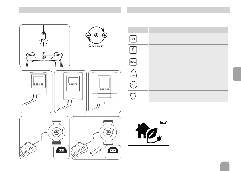
3 Connecting the measuring cables
ÎIn order to switch on the device, press button ⚭.
The home screen will be shown.
ÎIn order to access the menu, press button ☰.
4 Operation and function
The device is operated via the 6 push buttons below the
display.
Button Function
Switching on / off device
Switching on / off display illumination
Scrolling through the menu
Increasing adjustment values
Switching on / off signal
Reducing adjustment values
PWM
/
0-10V
PWM
/
0-10V
R1-R3
R4
R4
VBus
VBus
GND
V40
PWM2
PWM1
S5
S4
S3
GND N
VFS
RPS
Temp. Sensor
Pt1000
S2
S1
R3
R2
R1
L'L
IP20
1(1)A (100 ... 240) V~
2(1)A (100 ... 240) V~
100...240 V~
T4A
50-60Hz
PWM 2
PWM 1
GND
2
PWM / 0-10V
PWM
/
0-10V
PWM
/
0-10V
R1-R3
R4
R4
VBus
VBus
GND
V40
PWM2
PWM1
S5
S4
S3
GND N
VFS
RPS
Temp. Sensor
Pt1000
S2
S1
R3
R2
R1
L'L
IP20
1(1)A (100 ... 240) V~
2(1)A (100 ... 240) V~
100...240 V~
T4A
50-60Hz
PWM 2
PWM 1
GND
2
PWM / 0-10V
If the measuring cable is
connected to the controller
with wrong polarity,an error
message will be indicated.
⚠max. 18V
PR73B PR73B

en
14
1/6 Measuring a PWM input signal
measured PWM signal in %
PWM 60%
IN 1000 Hz
1/6
measured PWM frequency in Hz*
2/6 Generating the PWM output signal
generated PWM signal in %
PWM 100%
OUT 1000 Hz
Signal OFF
2/6
generated PWM frequency in Hz
signal on / off
3/6 Measuring a 0-10V input signal
measured 0-10V signal in %
measured voltage in V
4/6 Generating the 0-10V output signal
generated 0-10 V signal in %
generated voltage inV
signal on / off
* If the PWM signal measured is exactly 0% or 100%, no
PWM frequency can be measured. In this case, -- Hz
will be indicated.
ÎIn order to adjust the duty cycle of the PWM signal,
select the desired value using buttons ♉and ♊.The
adjusted value will be saved automatically.
ÎAdjust the frequency of the PWM signal with the pa-
rameter PWM in the 6/6 menu.
ÎIn order to switch the signal on or off,press button ♟.
ÎIn order to adjust the duty cycle of the 0-10 V signal,
select the desired value using buttons ♉and ♊.The
adjusted value will be saved automatically.
The voltage of the 0-10 V signal generated automatically
adapts to the duty cycle value.
ÎIn order to switch the signal on or off,press button ♟.
0-10V 26%
IN 2,6V
3/6
0-10V 0%
OUT 0,0V
Signal OFF
4/6

en
15
5/6 Measuring and generating a PWM signal
(for bidirectional pumps)
generated PWM signal in %
signal on / off
6/6 Settings
touch-tone on / off
adjust display brightness
adjust PWM frequency
adjust pump type
measured PWM signal in %
pump feedback (if available)**
ÎIn order to adjust the duty cycle of the PWM signal,
select the desired value using buttons ♉and ♊.The
adjusted value will be saved automatically .
ÎIn order to switch the pump on or off,press button ♟.
** Adjust the pump type by means of the parameter Feed-
back in the 6/6 menu, for correct pump feedback.
ÎIn order to scroll through the menu, press button ♟.
The menu line selected is highlighted.
ÎIn order to carry out adjustments, select the menu line
and adjust the values with the buttons ♉and ♊.The
adjusted values will be saved automatically.
Adjustment
channel/ menu
Adjustment range/selection Factory
setting
2/6
PWM 0 … 100 % 100 %
Signal ON, OFF OFF
4/6
0-10 V 0 … 100 % 0 %
Signal ON, OFF OFF
5/6
PWM OUT 0 … 100 % 100 %
Signal ON, OFF OFF
6/6
Beep ON, OFF OFF
LCD 0 … 100 % 50 %
PWM 290 … 2000 Hz 1000 Hz
Feedback Wilo S (solar),Wilo H (heating),
Grundfos, none none
PWM OUT 100%
Signal OFF
PWM IN 60%
5/6
Flow rate: 1000 l/h
SETUP
Beep OFF
LCD 50%
PWM 1000 Hz
Feedback none
6/6

en
16
©All contents of this document are protected by
copyright.
5 Battery
The device is equipped with a battery indicator:
In order to replace the batteries, proceed as follows:
Batteries and rechargeable batteries contain toxic
substances and must not be disposed of in regular
household waste.
Remove the batteries if you do not use the device
for a longer period of time.
SOREL GmbH Mikroelektronik
Reme-Str. 12
58300 Wetter
Important note
The texts and drawings in this manual are correct to the
best of our knowledge. As faults can never be excluded,
please note:
Your own calculations and plans, under consideration of
the current standards and directions should only be basis
for your projects.We do not oer a guarantee for the com -
pleteness of the drawings and texts of this manual - they
only represent some examples.They can only be used at
your own risk.No liability is assumed for incorrect,incom -
plete or false information and/or the resulting damages.
Note
The design and the specifications can be changed without
notice.
The illustrations may dier from the original product.
Table of contents
Popular Test Equipment manuals by other brands

Klein Tools
Klein Tools GL1200 instruction manual

Gossen MetraWatt
Gossen MetraWatt ProFiTEST C-GB int. operating instructions

METREL
METREL OmegaPAT XA MI 3360 instruction manual

Dillon
Dillon Quantrol AFG Series user manual

Tonghui Electronics
Tonghui Electronics TH9201 Series Operation manual

Witschi
Witschi Proofmaster S Service manual


