Tonghui Electronics TH9201 Series User manual

◇1
TH9201 Series
AC/DC Withstanding Voltage/
Insulation resistance Tester
Operation Manual
First Edition
Tonghui Electronic Co.,Ltd.
www.tonghui.com.cn

◇2
Content
CHAPTER 1 SETUP..................................................................................................................... 4
1.1 UNPACKING.......................................................................................................................... 4
1.2 PRECAUTIONS FOR INSTALLATION ....................................................................................... 4
1.2.1 Do not use the tester in a flammable atmosphere. ........................................................ 4
1.2.2 Avoid locations where the tester is exposed to high temperatures or direct sunlight. .. 4
1.2.3 A void humid environments. ........................................................................................ 4
1.2.4 Do not place the tester in a corrosive atmosphere. ....................................................... 5
1.2.5 Do not locate the tester in a dusty environment............................................................ 5
1.2.6 Do not use the tester where ventilation is poor............................................................. 5
1.2.7 Do not place the tester on a tilted surface or in a location subject to vibrations........... 5
1.2.8 Do not use the tester in locations affected by strong magnetic or electric fields.......... 5
1.2.9 Do not use the tester in locations near a sensitive measuring....................................... 5
instrument or receiver............................................................................................................ 5
1.3 PRECAUTIONS FOR MOVING ................................................................................................. 6
1.3.1 Before moving the tester, turn off the power switch..................................................... 6
1.3.2 When moving the tester, Disconnect all wires from it.................................................. 6
1.4 CHECKING AND REPLACING FUSE ......................................................................................... 6
1.5 CONNECTING THE AC POWER CORD.................................................................................... 7
1.6 GROUNDING ......................................................................................................................... 7
1.7 CHECKING OPERATIONS....................................................................................................... 8
1.8 OTHER SPECIFICATIONS........................................................................................................ 9
CHAPTER 2 PRECAUTIONS ON HANDLING....................................................................... 10
2.1 PROHIBITED OPERATIONS .................................................................................................. 10
2.1.1 Do not turn on/off the power repeatedly..................................................................... 10
2.1.2 Do not short the output to the earth ground ................................................................ 10
2.1.3 Do not apply an External Voltage............................................................................... 10
2.2 ACTION WHEN IN EMERGENCY ...........................................................................................11
2.3 PRECAUTIONS ON TESTING..................................................................................................11
2.3.1 Wearing Insulation Gloves ..........................................................................................11
2.3.2 Precautions for Pausing Tests......................................................................................11
2.3.3 Items Charged Up to Dangerous High Voltages..........................................................11
2.3.4 Matters to be Sure of After Turning-OFF Power.........................................................11
2.3.5 Warnings for Remote Control......................................................................................11
2.4 WARNING FOR RESIDUAL HIGH VOLTAGES ....................................................................... 12

◇3
2.5 DANGEROUS STATES OF FAILED TESTER ........................................................................... 12
2.6 TO ENSURE LONG-TERM USE WITHOUT FAILURES ........................................................... 13
2.7 DAILY CHECKING............................................................................................................... 13
CHAPTER 3 PART NAMES AND FUNCTIONS..................................................................... 15
3.1 FRONT PANEL..................................................................................................................... 15
3.2 INSTRUCTION OF REAR PANEL ............................................................................................ 17
3.3 DESCRIPTION...................................................................................................................... 19
CHAPTER 4 BASIC OPERATION ............................................................................................ 24
4.1 TURNING ON THE POWER ................................................................................................... 24
4.1.1 Turning on the power.................................................................................................. 24
4.2 INSTRUCTION OF INTERFACE FUNCTION ............................................................................. 25
4.3 TEST ITEM INTERFACE AND PARAMETER SETUP................................................................. 30
4.4 TEST FUNCTION THEORY AND INSTRUCTION ...................................................................... 32
CHAPTER 5 TH9201 RS232 Commands……………………………………………………... 37

◇4
Chapter 1 Setup
This chapter describes the procedures from unpacking to installation to
operation checking.
1.1 Unpacking
Upon receiving the product, confirm that the necessary accessories are included and
have not been damaged in transit. Should any damage or shortage be found, please
contact TongHui distributor/agent.
Items Quantity
TH9201/S / B/C 1
TH90003R withstanding-voltage test leadwires 1
TH90003B withstanding-voltage ground leadwires 1
3A(220V)/5A(110V)Fuse (TH9201/S)2
2A(220V)/3A(110V)Fuse (TH9201B/C)2
TH90004 withstanding-voltage test stick 1
TH26034 RS232C cable 1
AC Power cord 1
Operation Manual 1
Tes t R e po rt 1
Servicing card 1
Accessories ordered by custom 1
1.2 Precautions for Installation
Be sure to observe the following precautions when installing the tester.
1.2.1 Do not use the tester in a flammable atmosphere.
To prevent explosion or fire, do not use the tester near alcohol, thinner, or other
combustible materials, or in an atmosphere containing such vapors.
1.2.2 Avoid locations where the tester is exposed to high temperatures
or direct sunlight.
Do not locate the tester near a heater or in areas subject to drastic temperature
changes.
Operating temperature range: 5 °C to +35 °C
Storage temperature range: -20 °C to +60 °C
1.2.3 A void humid environments.

◇5
Do not locate the tester in a high-humidity environment—near a boiler, humidifier, or
water supply.
Operating humidity range: 20 % to 80 % RH (no dew condensation permitted)
Storage humidity range: 90 % RH or less (no dew condensation permitted)
Condensation may occur even within the operating humidity range. In that case, do not
start using the tester until the location is completely dry.
1.2.4 Do not place the tester in a corrosive atmosphere.
Do not install the tester in a corrosive atmosphere or one containing sulfuric acid mist or
the like. This may cause corrosion of various conductors and imperfect contact with
connectors, leading to malfunction and failure, or in the worst case, a fire.
1.2.5 Do not locate the tester in a dusty environment.
Dirt and dust in the tester may cause electrical shock or fire.
1.2.6 Do not use the tester where ventilation is poor.
This tester features a forced-air cooling system. Provide sufficient space for the air inlet
on the lateral side and the air outlet on the rear side to allow air to flow.
1.2.7 Do not place the tester on a tilted surface or in a location subject
to vibrations.
If placed on a non-level surface or in a location subject to vibration, the tester may fall,
resulting in damage and injury.
1.2.8 Do not use the tester in locations affected by strong magnetic or
electric fields.
Operation in a location subject to magnetic or electric fields may cause the tester to
malfunction, resulting in electrical shock or fire.
1.2.9 Do not use the tester in locations near a sensitive measuring
instrument or receiver.
Operation in a location subject, may cause such equipment may be affected by noise
generated by the tester.
At a test voltage exceeding 3 kV, corona discharge may be generated to produce
substantial amounts of RF broadband emissions between grips on the test leadwire. To
minimize this effect, secure a sufficient distance between alligator clips. In addition, keep
the alligator clips and test leadwire away from the surfaces of conductors (particularly
sharp metal ends).

◇6
1.3 Precautions for Moving
When moving the tester to the installation site or otherwise transporting it, take the
following precautions:
1.3.1 Before moving the tester, turn off the power switch.
Transporting the tester with its POWER switch on can lead to electric shock and
damage.
1.3.2 When moving the tester, Disconnect all wires from it.
Moving the tester without disconnecting the cables may result in breakage of the wire or
injury due to the tester tipping over.
! WARNING:This instrument is designed to operate from the overvoltage category II.
Do not operate it from the overvoltage category III or IV.
Before turning on the power, make sure of the fuse and the source voltage agree with
the LINE-VOLTAGE RANGE switch on the rear panel.
Nominal voltage range (allowable voltage range):
100 V to 120 V AC (85 V to 132 V AC)
200 V to 240 V AC (170 V to 250 V AC)
Allowable frequency range: 47 Hz to 63 Hz
!WARNING To prevent malfunctions, be sure to operate within the line-voltage range.
1.4 Checking and replacing fuse
!WARNING To prevent electric shock, before checking or replacing the fuse, be sure
to turn off the POWER switch and unplug the AC power cord.
Make sure that the fuse used conforms to the instrument specifications, including shape,
rating, and characteristics. Using a fuse with different rating or short-circuiting, the fuse
holder will damage the instrument.
1. Turn off the POWER switch, and unplug the AC power cord.
2. On the rear panel, remove the fuse holder, by pushing it inward and unscrewing it

◇7
counterclockwise using a screwdriver.
3. In accordance with the fuse rating specified below, check the fuse type and replace
the fuse.
4. Following the above steps in the reverse order, reinstall the fuse holder.
Voltage range Frequency Fuse type Power
100-120V 5A(TH9201/S)
3A(TH9201B/C)
200-240V
47-63Hz 3A(TH9201/S)
2A(TH9201B/C)
500VA
1.5 Connecting the AC Power Cord
The power cord that is provided varies depending on the destination for the product at
the factory-shipment.
Do not use the AC power cord provided with the product as a AC power cord for
other instruments.
Connection procedure:
1. Confirm that the supply voltage is within the line voltage range of the tester.
2. Confirm that the POWER switch on the tester is off.
3. Connect the AC power cord to the AC LINE connector on the rear panel.
Use the provided power code or power code that is selected by qualified personnel.
4. Plug in the AC power cord.
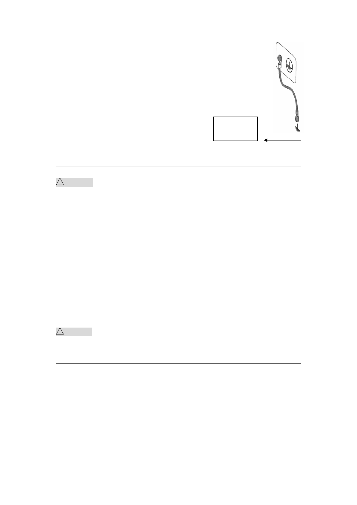
1.6 Grounding
!WARNING Be sure to connect the tester to an electrical ground (safety ground). If the
output to a conveyer or peripheral device that is connected to an earth ground or a
nearby commercial power line is short-circuited without grounding, the tester chassis is
charged to an excessively high voltage, resulting in extreme danger.
This tester is designed as a ClassI equipment (equipment protected against electric
shock with protective grounding in addition to basic insulation). Therefore, electric shock
may occur without proper grounding.
To ensure safety, be sure to ground the tester.
Choose either of the following two available methods of doing so:
◇8
1. Connect the AC power cord to a three-contact grounded electrical outlet.
2. Connect the protective conductor terminal on the rear panel to the earth
ground.
Have specialized engineers select, manufacture, and install cables.
To ensure secure connection, use proper tools.
1.7 Checking Operations
!WARNING Use the interlock jumper only to quickly cancel the protection status.
When using this tester, use the interlock function as much as possible to ensure a safe
operating environment. To use jigs in withstanding voltage or insulation resistance
testing, provide a cover or other means for the DUT to prevent electric shock by cutting
off the output when the cover is opened. It is also recommended that an enclosure be
provided around the
operating area and that output be cut off every time the door is opened.
Before turning on the power, confirm that the allowable voltage range indicated on the
power supply is the same as that indicated on the rear panel of the tester.
When the power is turned on, the tester lights all LEDs on the front panel and
self-diagnosis is started.
Before starting up the tester, confirm that all LEDs are on to ensure safety.
It is particularly dangerous to start a test when the DANGER lamp is broken.
Note that, in self-diagnosis, even when the DANGER lamp is lighting, no output or
voltage is being generated.
!CAUTION After turning off the POWER switch, wait several seconds before turning it
on. Turning the POWER switch on/off repeatedly with insufficient intervals may damage
the tester.
Checking procedure:
1. Confirm that the allowable voltage range indicated on the power supply is the same as
that indicated on the rear panel.
2. Confirm that the AC power cord is properly connected to the AC LINE connector on
Earth
ground

◇9
the rear panel.
3. Plug in the AC power cord.
4. Turn on the POWER switch. Confirm that all LEDs on the front panel are lit.
Following the opening screen, display the ACW screen
5. Turn off the POWER switch.
6. Turn on the POWER switch again.RN
7. Following the opening screen, display the ACW screen and confirm that
the tester is kept in the READY status.
The above steps complete the checking procedure.
Opening screen:
同 惠 电 子
T H 9 2 0 1
VERSION 1.0
1.8 Other specifications
1. Power:≤500VA(TH9201/S)
≤350VA (TH9201B/C)
2.Dimensions:330mm*140mm*385mm;
3.Weight:20kg(TH9201/S)16kg(TH9201B/C).

◇10
Chapter 2 Precautions on Handling
This chapter describes the precautions to be followed in the handling of this tester.
When using the tester, take utmost care to ensure safety.
!WARNING The tester derivers a 5 kV test voltage which can cause human
injury or death. When operating the tester, be extremely careful and observe the cautions,
warnings, and other instructions given in this chapter.
2.1 Prohibited Operations
2.1.1 Do not turn on/off the power repeatedly
After turning OFF the power switch, be sure to allow several seconds or more before turning it
ON again. Do not repeat turning ON/OFF the power switch rapidly. If you do this, the
protectors of the tester may not be able to render their protective functions properly. Do not
turn OFF the power switch when the tester is delivering its test voltage–you may do this only in
case of emergency.
2.1.2 Do not short the output to the earth ground
Pay attention so that the high test voltage line is not shorted to a nearby AC line or nearby
devices (such as conveyors) which are connected to an earth ground. If it is shorted, the tester
chassis can be charged up to the hazardous high voltage. Be sure to connect the protective
grounding terminal of the tester to an earth line. If this has been securely done, even when the
HIGH VOLTAGE terminal is shorted to the LOW terminal, the tester will not be damaged and
its chassis will not be charged up to the high voltage.
Be sure to use a dedicated tool when grounding the protective grounding terminal.
!CAUTION The term "AC line" here means the line on which the tester is operating. That is
the line to whose outlet the AC power cable of the tester is connected. It may be of a
commercial AC power line or of a private-generator AC power line.
2.1.3 Do not apply an External Voltage
Do not apply a voltage from any external device to the output terminals of the tester.
The analog voltmeter on the front panel cannot be used as stand-alone voltmeter.
They may be damaged if their output terminals are subject to an external voltage.

◇11
2.2 Action When in Emergency
In case of an emergency (such as electric shock hazard or burning of DUT), take the
following actions. You may do either (a) or (b) first. But be sure to do both.
1.Turn OFF the power switch of the tester.
2.Disconnect the AC power cord of the tester from the AC line receptacle.
2.3 Precautions on Testing
2.3.1 Wearing Insulation Gloves
When handling the tester, be sure to wear insulation gloves in order to protect yourself
against high voltages. If no insulation gloves are available on your market, please order
Kikusui distributor/agent for them.
2.3.2 Precautions for Pausing Tests
When changing test conditions, press the STOP switch once to take precautions. If you are not
going to resume the test soon or if you are leaving the Test area, be sure to turn-OFF the
POWER switch.
2.3.3 Items Charged Up to Dangerous High Voltages
When in test, the DUT, test leadwires, probes, and output terminals and their vicinities can be
charged up to dangerous high voltages. Never touch them when in test.
!WARNING The vinyl sheaths of the alligator clips of the test leadwires which are supplied
accompanying the tester have no sufficient insulation for the high test voltages. Never touch
them when in test.
2.3.4 Matters to be Sure of After Turning-OFF Power
If you have to touch the DUT, test leadwires, probes, and/or output terminals and their
vicinities for re-connections or other reasons, be sure of the following two matters.
1. The analog voltmeter indicates “zero.”
2. The DANGER lamp has gone out.
2.3.5 Warnings for Remote Control
Be extremely careful when operating the tester in the remote control mode in which
the dangerous high test voltage is ON/OFF-controlled remotely. Provide protective
means as follows:
1. Provide means to assure that the test setup does not become the test voltage is being
delivered by inadvertent operation.
2. Provide means to assure that none can touch the DUT, test leadwires, probes, output
terminals and their vicinities when the test voltage is being delivered.

◇12
2.4 Warning for Residual High Voltages
!WARNING In DC withstanding voltage testing and insulation resistance testing, the test lead
wire, test probe, and DUT are charged to a high voltage. The tester is equipped with a
discharge circuit, but some time is nonetheless required to discharge them after the output is
cut off. There is a danger of electric shock during discharge. To avoid electric shock, take the
utmost care to ensure that the DUT, test lead wire, probe, and highly charged parts around the
output terminal are not touched. If it is necessary to touch them, be sure to confirm both (1)
and (2):
(1) The analog voltmeter indicates “zero.”
(2) The DANGER lamp has gone out.
As soon as the output is cut off, the tester’s discharge circuit starts forced discharging. Do not
disconnect the DUT during a test or prior to completion of discharging.
Discharge time
The length of the discharge time varies according to the properties of the DUT.
Discharge is conducted at a resistance of approximately 2 k in DC withstanding
voltage testing, and at 10 k in insulation resistance testing.
When no DUT is connected, the tester itself requires the following lengths of time
to reduce the internal capacitor voltage to 30 V.
If the DUT is disconnected during a test or before the completion of discharging, assuming that
the DUT has a capacity of 0.01uF and a parallel resistance of 100 M, approximately 5.3
seconds at 5 kV and approximately 3.5 seconds at 1 kV are required for the DUT to discharge
to 30 V.
When the approximate time constant of the DUT is known, the time required for discharging to
30 V after the output is cut off is calculated as the time constant times the value given above.
2.5 Dangerous States of Failed Tester
Typical possible dangerous states of the tester are as shown below and in which cases the
most dangerous situation that “the high test voltage remains delivered and won't be
turned off!” may occur. When this situation has occurred, immediately turn OFF the power
switch and disconnect the AC power cable from the AC line receptacle.
•The DANGER lamp does not go out despite you have pressed the STOP switch.
•The DANGER lamp does not light up despite the pointer of the analog voltmeter is
deflected indicating that the output voltage is being delivered.
Also when the tester is in other malfunctioning states than the above, there is a possibility
that the output voltage is delivered irrespective of your proper operating procedure. Never use

◇13
the tester when it has failed.
!WARNING Keep the tester away of other people until you call our service engineer for help.
Immediately call Tonghui distributor/agent. It is hazardous for an unqualified person to attempt
to troubleshoot any tester problem.
2.6 To Ensure Long-Term Use without Failures
The withstanding voltage-generating block of the tester is designed to release half the rated
amount of heat, in consideration of the size, weight, cost, and other factors of the tester. The
tester must therefore be used within the ranges specified below. If you deviate from these
ranges, the output block may be heated to excess, activating the internal protection circuit.
Should this happen, wait until the temperature returns to the normal level.
Output requirements for withstanding voltage testing
Ambient
temperature Upper current Pause Time Output time
>20mA
(TH9201/S)
>12mA
(TH9201B/C)
At least as long as the
output time
Maximum of 1
minute
AC <10mA
(TH9201/S)
<6mA
(TH9201B/C)
Not necessary Continuous output
possible
>6mA(TH9201/S)
>3m(TH9201B/C)
At least as long as the
output time
Maximum of 1
minute
T≤40℃
DC
<5mA(TH9201/B)
<2mA(TH9201B/C)
At least as long as the
judgment
wait time (WAIT TIME)
Continuous output
possible
(Output time = voltage rise time + test time + voltage fall time)
2.7 Daily Checking
To avoid accidents, confirm at least the following before starting operation:

◇14
1. The tester is connected to an earth ground.
2. The coating of the high-voltage test lead wire is free from cracks, fissures, and breakage.
3. The high-voltage test lead wire is not broken.
4. The tester generates FAIL signal when the ends of the low-voltage test lead wire and
high-voltage test lead wire are short-circuited.
◇15
Chapter 3 Part names and Functions
This chapter describes the names and functions of components such as switches,
displays, and connectors on the front and rear panels.
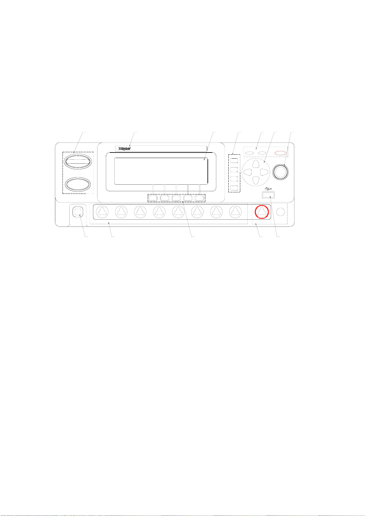
3.1 Front Panel
POWER
TEST
SETUP
SYSTEM
MEMORY
CH1 CH2 CH3 CH4 CH5 CH7CH6 CH8 OUTPUT RTN/LOW
PASS FAIL
ENTRY
AC/DC/IR/SC DANGER
TH9201S HIPOT TESTER
START
STOP
412 356
7
12 11 10 9 8
Figure 3-1
1.START and STOP
Start up the instrument, once test starts, “TEST” will be displayed at the left corner of the
screen, TEST indicator lights.
Stop key, used to cancel the test;Or PASS、FAIL status.
2. Band and model
3. LCD screen
240×64 dot- matrix LCD screen, display setting and test interface .etc.
4. FUNCTION
Select mode, system, interface..
●TEST
Press the key, and the corresponding key lights, the instrument is ready to test.
●SETUP
Press the key, and the corresponding key lights, the instrument enters parameter setting;
●SYSTEM
Press the key, and the corresponding key lights, display system setting interface;

◇16
Including SYSTEM1、SYSTEM2 and INTERFACE.
5. Indicator
●TEST
In the process of testing, it lights in output voltage.
●PASS
Indicate a test result, it lights in PASS;
When time function is off,(TIMER OFF),no PASS judge.
●FAIL
Indicate a test result, it lights in FAIL.
6. Direction key
Move direction key to the required setting test condition;
Press SHIFT and TS to change LCD display contrast.
7. Code switch
When in READY status, set the test condition on LCD.
8. USB interface
Externally connect to USB storage
9. Output voltage HIGH and LOW terminal
High and low voltage terminal in test voltage output.
!Warning:In the process of testing,don’t touch the high terminal
Caution:if external voltage is used in test terminal, it will cause the damage of internal circuit.
10. Shortcut key(F1-F5)
Corresponding with the function operation or shortcut key on LCD.
11. 8 channel sweep interface(only for TH9201S)
Internal 8 channel sweep output interface.
12.POWER

◇17
3.2Instruction of rear panel
WARNING:FOR CONTINUED PROTECTION AGAINST FIRE
HAZARD,REPLACE ONLY WITH THE SAME TYPE AND RATING OF FUSE
AS SPECIFIED FOR THE LI NE VOLTAGE BEING UTI LIZED.
CAUTION:NO OPERATOR SERVICEABLE P ARTS INSIDE
REFER SERVICING TO QUAL ITIFIED PERSONNEL.
90V-110V~
108V-132V~
198V-242V~
216V-250V~
5AT
250V
2.5AT
250V
HIGH VOLTAGE
MAX:5kV AC 30mA/6kV DC 10 mA
HV OUTPUT RTN/
LOW
100V/120V/220V/240V~
50/60Hz 500W MAX
GPIB
CONT.
CHECK
OPTION
1Ω CAL
VOLTAGE SELECTOR
POLLUTION DEGREE 2
INSTALLATION CATEGORY Ⅱ
贴标签
!
!
OUTPUT
FAIL
START
RESET
COM
INTER
LOCK
UNDER
TEST
PASS
15
9
UNDER RESET
TEST START
PASS FAIL
6
SCANNER
RS-232C
12345678
91011121314
Figure 3-2
i. Fan
Power amplifier circuit radiator.
ii. Line voltage range
Switch of input voltage range.
iii. PLC controller interface
Be used to connect programming controller, where:
INTERLOCK:input the connecting locked signal,if off, starting output is not allowed.
TEST:Output synchronized-signal control when high voltage output is started.
START:Input the starting signal for outputting high voltage,corresponding to START
signal on the front panel.
RESET:
PASS:
FAIL:
iv. OUTPUT
TEST outputs control,output 24V level or relay switch signal,it is suggested to use switch
signal to assure signal separation.
v. HANDEL interface
Use 9 core model D jack to output.
vi. Ground break-over test interface
When open ground break-over test function,the terminal has to be connected to the place
where DUT is connected with low terminal.
vii. SCAN interface
Be used to connect TH9121 multi-channel tester.
viii. IEEE488(GPIB)parallel communication interface
Provide the general communication interface for instrument and external device.

◇18
ix. Protective earth terminal
Be used to connect instrument to ground.
x. RS232C serial interface
Serial communication, realize the communication with computer.
xi. Power jack
Be used to input AC power; please use the attached power line with fuse. Change the fuse
according to input power.
xii. Ground break-over calibration
Ground break-over resistance is 1 ohm,use potentiometer to calibrate if there is deviation.
xiii. Mark
This mark describes the instrument’s SN.
xiv. High voltage output interface(optional)
Stand-by high voltage output interface.

◇19
3.3 Description
TH9201 Provide 5kVAC/30mA withstanding voltage, 6kVDC/10mA withstanding voltage and
insulation resistance tester.
TH9201S Provide 5kVAC/30mA withstanding voltage, 6kVDC/10mA withstanding voltage
and insulation resistance with scanning test.
TH9201B Provide 5kVAC/20mA withstanding voltage, 6kVDC/5mA withstanding voltage and
insulation resistance test.
TH9201C Provide 5kVAC/20Ma withstanding voltage test.
In high voltage modular, there is a AB power amplifier power which can assure the
programming of output voltage as well as the isolation of output voltage power and line power.
40~600Hz high voltage transformer can rise voltage, and use high voltage feedback loop to
assure the accuracy of output voltage, then the actual voltage adjustment rate is far smaller
than that of transformer, which can be used to the product whose VA is larger than the actual
power.
In AC output, set the operation in 50 or 60Hz,not being limited by line voltage, the voltage
waveform isn’t affected by line voltage neither. The instrument also has the real current test,
and then the large current generated by distributed capacitance can’t affect the judgment of
real insulation.
To DC and insulation resistance test, TH9201/S/B tester use 600Hz AC to form DC
voltage to be the power, which can assure the DC power ripple is far less than the formal
withstanding voltage tester, thus to assure the stability of 5000V, 10mA test.
Once connecting the load, TH9201 not only can perform the independent AC withstanding
test, DC withstanding voltage test, insulation resistance test, but also multi –item test via the
setting of test programme. When connecting with high voltage scanner TH9121, perform
multi-items and multi-products test via setting the item of test programme. Each scanner can
adopt 8 channels. The tester can be connected to two scanners, reach to 16 channels totally.
TH9201 series all allocate PLC interface, RS-232C、GPIB(optional),thus the instrument
can adapt to the auto test system of different required safety and reliability.
Feature:
■3 test functions—AC withstanding voltage test, AC withstanding voltage test and
insulation resistance test.
TH9201/S/B provides AC withstanding voltage test and insulation resistance test.H9201C
provides AC withstanding voltage test.
Once connected with load, the tester can perform different tests continually.
■ AC withstanding voltage test 5kV/30mA(TH9201/S)5kV/20mA(TH9201B/C)
In TH9201/S high voltage modular, there is a AB power amplifier circuit and a 150VA
transformer, which can realize the Max. output of 5kV/30mA(1 min),while TH9201B/C
power amplifier circuit and a 100VA transformer can realize the Max. output of 5kV/20mA
◇20
(1 min).
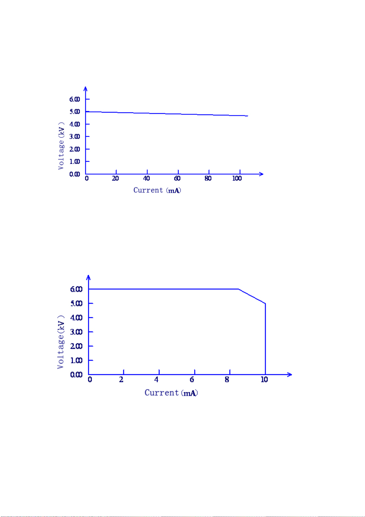
TH9201/S has the highest limit current 30mA,Min. voltage 50V,so instrument generates
the test voltage corresponding with 50Hz/60Hz ,independent power, auto voltage
adjusting rate is smaller than ±3%. It’s not necessary to adjust output voltage after setting
test voltage.
Figure 3-3 AC voltage load adjusting rate
DC withstanding voltage test 6kV(Max. output power is 50W)
TH9201 series can provide DC withstanding voltage test of wide voltage range(Max.
output power is 50W,the max. holding time is 1 min). Instrument allocates a reliable,
low ripple DC/AC switch circuit, voltage load adjusting rate≤1%.
Figure 3-4 DC voltage output range
Table of contents
Other Tonghui Electronics Test Equipment manuals


