Dillon Quantrol AFG Series User manual
Advanced Force Gauge (AFG/AFTI)
User’s Manual
Advanced Force Gauge User’s Manual
2
Risk of electrical shock. Do not remove cover. No user serviceable
parts inside. Refer servicing to qualified service personnel.
Weigh-Tronix reserves the right to change
specifications at any time.
CAUTION
EUROPEAN COUNTRIES
WARNING
This is a Class A product. In a domestic environment this
product may cause radio interference in which the user
may be required to take adequate measures.
07/22/04 AFG2003_U.P65 PN 29814-0013D e2 Printed in USA

Advanced Force Gauge User’s Manual 3
Table of Contents
Table of Contents...........................................................................................3
Introduction ....................................................................................................5
Before Use..............................................................................................5
Operation Overview ................................................................................5
Powering the AFG..........................................................................................5
Inserting and Charging the Batteries......................................................6
Using the AFG ...............................................................................................6
Fitting Accessories .................................................................................6
Mounting to a Test Stand ........................................................................7
Powering up............................................................................................7
Basic Functions ......................................................................................8
Optional Settings ..................................................................................12
Additional Force & Torque Sensors......................................................13
Advanced Menu Options ......................................................................14
ALARM ..........................................................................................15
PLC (Programmable Limit Controller) ...........................................20
STAND...........................................................................................21
FREEZE ........................................................................................23
% DROP ........................................................................................23
AVERAGE/TIME ............................................................................25
RATE .............................................................................................26
FOOTSWITCH 1 ...........................................................................26
FOOTSWITCH 2 ...........................................................................27
COMMS .........................................................................................27
INFORMATION..............................................................................28
CALIBRATION...............................................................................28
x/CONSTANT ................................................................................29
CONTRAST...................................................................................29
AFG Specifications ......................................................................................30
Appendix: Menu Flowcharts ........................................................................33

Advanced Force Gauge User’s Manual
4

Advanced Force Gauge User’s Manual 5
Powering the AFG for the First Time
Introduction
Before Use
Operation
Overview
Thank you for choosing the Quantrol Advanced Force
Gauge (AFG) instrument. With correct use and
regular re-calibration it will give many years of
accurate and reliable service.
The AFG uses the latest integrated circuit technology.
It can measure tensile and compressive forces
accurately, while being simple to use by the operator.
Quantrol offers a full range of force measurement
products to complement your force gauge, including
manual and motorized test stands and a large
assortment of grips and attachments. Ask your
Quantrol distributor for additional information.
Upon receiving the unit please check that no physical
damage has occurred to the packaging material,
plastic case or the instrument itself. If any damage is
evident please notify Quantrol immediately.
The most commonly used features (such as display-
ing force, peak hold, zero and changing of displayed
units) can all be done by pressing a single dedicated
key identified on the front panel with grey text – see
the Basic Functions section. For less frequently used
features, a number of menu “hot keys” are provided
so you can press and hold a menu key to access the
gauge configuration – see the Optional Settings
section.
To configure the advanced features of the gauge a full
menu-driven system is available by using the keys
identified on the front panel with red text – see the
Advanced Menu Options section.
The AFG is supplied with a set of 5 Nickel Metal
Hydride AAA rechargeable batteries. For safety
reasons during transportation the batteries are
shipped discharged. To obtain maximum battery life
we recommend that you charge them with the
charger/adaptor supplied for at least 14 -16 hours
when you first receive the AFG.
Important!
Charge the AFG for 14-
16 hours before use.
Advanced Force Gauge User’s Manual
6
Inserting and
Charging the
Batteries
Low Battery Warning
Installing alkaline
batteries
AC operation
Using the AFG
Fitting
Accessories
To insert the batteries, remove the battery cover on
the upper part of the rear of the gauge by undoing the
3 retaining screws. Fit the five batteries in the battery
holder ensuring that you observe polarity and the
batteries are placed on top of the release tag.
To remove the batteries simply pull the release tag.
Refit the battery cover and tighten the 3 retaining
screws. Connect the AC charger to the AFG charger
socket located at the right hand side of the gauge next
to the display and charge the batteries for 14-16
hours. Only use the adaptor/charger supplied.
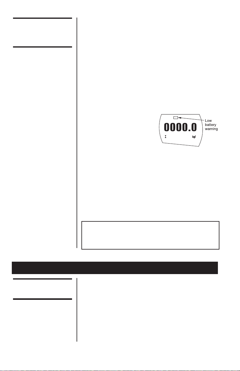
A low battery symbol will
appear in the display
approximately two minutes
before the gauge powers
down automatically.
The AFG can also be powered directly from
the AC adapter/charger. You can use the adapter
without the batteries present. Connect the AC
adapter/charger to your power supply.
If rechargeable batteries are installed, a trickle charge
will be applied to the batteries.
The AFG can also be powered by five AAA 1.5V
alkaline batteries (not supplied).
Warning: When alkaline batteries are installed, the
AC adaptor/charger must NEVER be connected to the
AFG due to the risk of acid leakage which could
damage the instrument.
The Rotary Coupling is supplied with AFG instruments
between capacities of 10N to 1000N. It allows you to
orientate the gripping accessory without the need for
a locking wheel (as on the extension rod).
We do not recommend it to be used for AFG 2.5N and
5N due to its weight, which would need to be tared
from the measuring range.
Affix the Rotary Coupling to the male thread of either
the short extension rod (1 inch long) or the long
Only use the adaptor/
charger supplied.
Note: When fitting a grip
ensure that it is screwed
finger-tight only.
Excessive torque can
damage the load cell.
Advanced Force Gauge User’s Manual 7
Mounting to a
Test Stand
Note: When fitting a grip
ensure that it is screwed
finger-tight only.
Excessive torque can
damage the load cell.
Powering up
Please note that an AFG
measuring very low
forces may not show
zero if it is moved during
the self test routine.
Once it is properly
mounted and zeroed the
reading will be stable.
extension rod (5 inches long). Affix the extension rod
to the load cell probe in the hole at the bottom of the
gauge by tightening it gently with the fingers.
Your chosen grip or accessory may now be connected
to the rotary coupling.
On the rear of the gauge there are two M5 threaded
holes, which can be used for mounting the gauge to a
Quantrol test stand. Each Quantrol test stand is
supplied with a dedicated dovetailed mounting bracket
and screws for this purpose. If you wish to mount to
another type of stand, ensure that the screws used
are threaded into the gauge to a maximum depth of
0.21 inch. The final thread is peaned but if screws are
fitted beyond this depth, damage to the internal PCB
may occur.
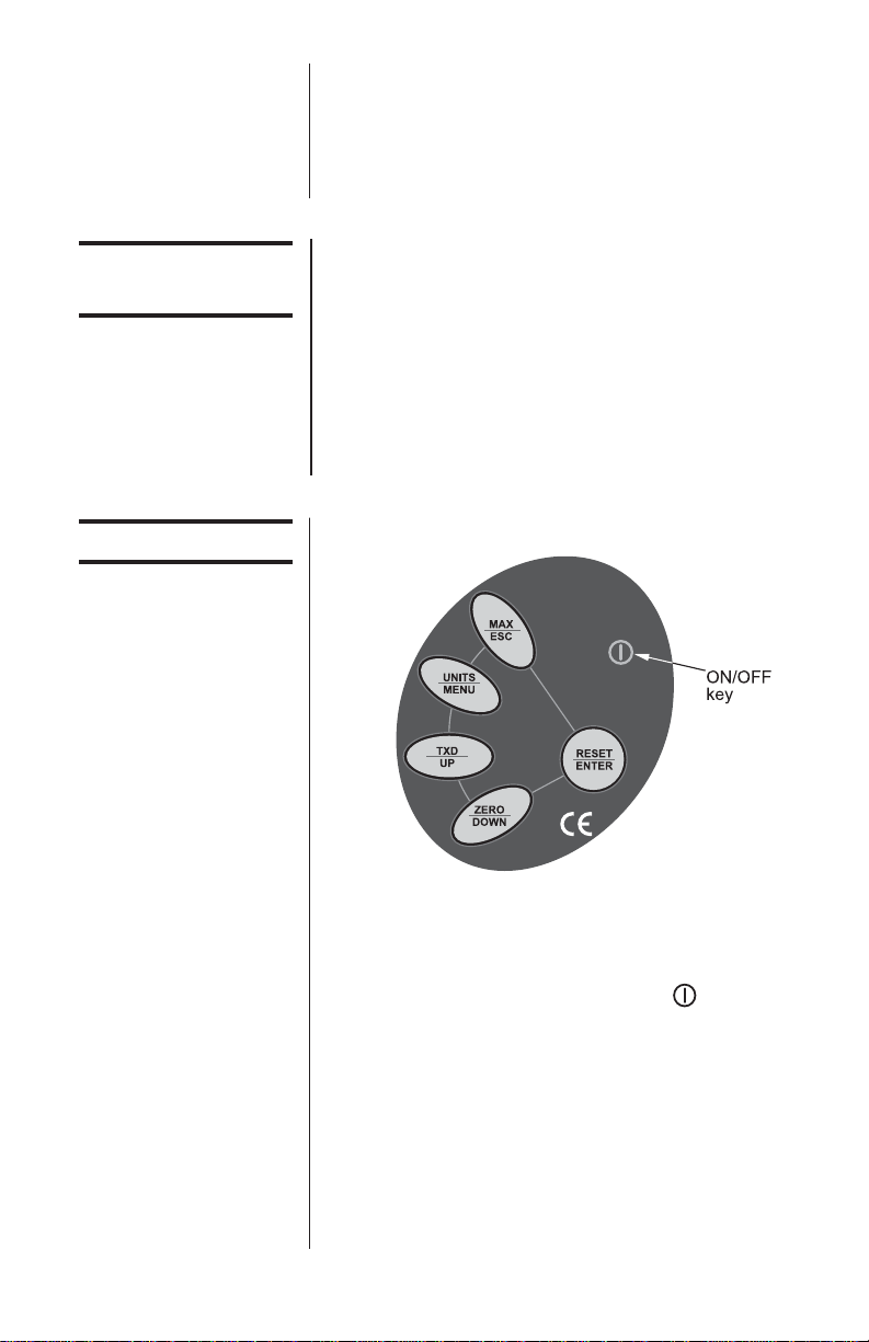
As shown in Figure 1 the control panel has six keys.
Figure 1
AFG control panel
To power up the gauge press the red key. A short
self test runs during which the display will show the
model and capacity in Newtons.
After the self test, providing no load has been applied
to the instrument, the display will show all zeroes.
This is because the gauge rezeroes itself during the
self test routine.
If a force is applied via the load cell probe (hole at
bottom of AFG), the reading on the display will
register the applied force.
Advanced Force Gauge User’s Manual
8
All the current settings
are saved when the
gauge is turned off and
the gauge will function in
the same mode when
powered up again.
Basic Functions
Display of Tension/
Compression
If the AFG has suffered a
serious overload
condition, the load
indicator bar will be
partially displayed even
when no load is present.
This is a warning that the
load cell is damaged and
you should immediately
contact your supplier to
arrange repair.
* Do not overload the load sensor. This will cause
irreparable damage. Forces greater than 120% of full-
scale will produce an audible beep until load is
released and an OL symbol will appear on the display
for 30 seconds.
Forces greater than 150% of full-scale will produce an
audible beep until load is released and an OL symbol
will appear permanently on the display. Consult your
supplier to arrange repair.
To power down the gauge press the red key.
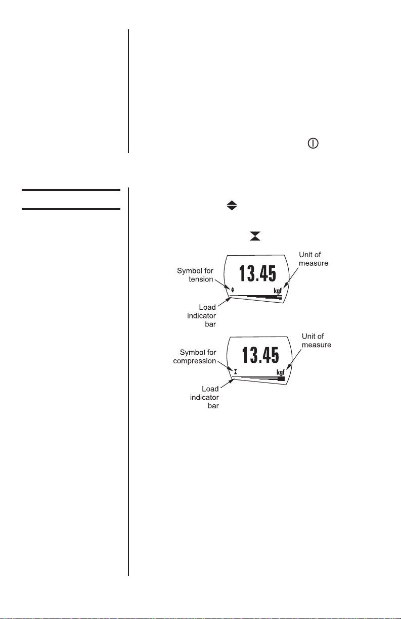
Tensile forces are displayed on the AFG and recog-
nized by the symbol
Compressive forces are displayed on the AFG and
recognised by the symbol
Figure 2
Tension and compression displays
A load indicator bar alerts the operator to how much
load has been applied to the load sensor. As the load
approaches the maximum rating of the load sensor,
the indicator bar changes appearance when above
approx. 80% of the rated capacity. This warns you
that steps should be taken to prevent excessive load
being applied.
For tensile forces the indicator bar is solid then
dotted. For compressive forces the indicator bar is
dotted then solid. See Figure 2.

Advanced Force Gauge User’s Manual 9
Zeroing the Gauge
Changing the Unit
of Measure
Max (peak) Readings
“Max” Mode
During the operation of the gauge it is often necessary
to zero the display – e.g. when you wish to tare out
the weight of a grip, so it does not become part of the
measured reading. Press and release the ZERO key.
The display will blink momentarily as the zero opera-
tion is carried out.
You can choose from the following units of measure
depending on the capacity of your gauge:
milliNewtons, kiloNewtons, Newtons, gram-force,
kilogram-force, ounce-force or pound-force.
To change the display units press and release the
UNITS key. Each successive key press will select the
next available units until the gauge returns to its
original setting. The AFG automatically converts
readings as new units of measure are selected.
The gauge detects and stores maximum (peak) force
in both compressive and tensile directions.
Press the MAX key. The display will show the word
MAX together with the highest tensile force and the
highest compressive force detected during the test.
The current load being applied to the load sensor is
also displayed. See Figure 3a.
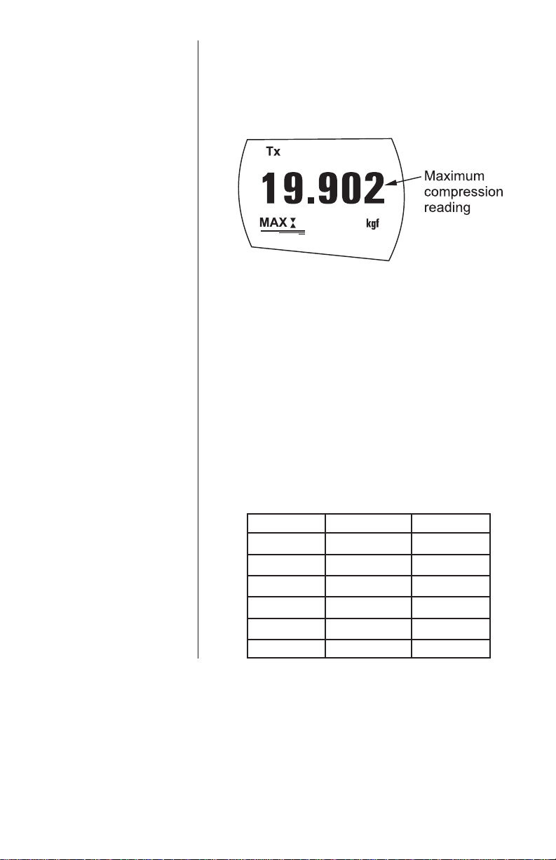
Press the MAX key again and the display will show
the maximum tensile force identified by the symbol
. See Figure 3b. Press the MAX key again and the
display will show the maximum compressive force
identified by the symbol. See Figure 3c.
Figure 3a
Dual Max

Advanced Force Gauge User’s Manual
10
“Normal” mode
Data Output
Analog output
RS232 and Mitutoyo
output signals
Figure 3b
Max Tension
Figure 3c
Max Compression
Press the MAX key again and the word MAX has now
disappeared from the display. The display will now
indicate forces applied in both directions as they are
applied to the load sensor and maintain a live display.
Press the RESET key to clear both maximum regis-
ters and prepare for detecting the next maximum
readings.
(See also COMMS section of Advanced Menu
Options)
A calibrated analog output is available from the top ‘D
type’ connector. See Specifications for details.
It is possible to transmit the displayed reading to
peripheral devices (e.g. PC, printer) by pressing and
releasing the TXD key. Displayed readings can also
be requested individually from a PC via the RS232
interface by sending a”?” (ascii D63 [3fh] character).
Advanced Force Gauge User’s Manual 11
Continuous PC
Communication For sending a continuous data stream to a PC, press
and hold the TXD key for 2 seconds then release. TX
will now appear in the display to indicate that data is
being sent. See Figure 4.To stop sending data, simply
press and release the TXD key, at which point TX will
disappear from the display.
Figure 4
AFG uses 2400, 9600,
57600 or 115200 Baud, 8
data bits, 1 start bit, 1
stop bit and no parity.
(See Advanced Menu
Options for setup details)
A full range of data
cables are available to
connect your gauge to
peripheral devices –
contact your supplier.
Data is output at
approximately 12 Hz.
Only prints large
displayed number in dual
display mode.
Computer Control of
Force Gauge
Key ASCII code Character
TXD 1 <Ctrl> A
UNITS 2 <Ctrl> B
MAX 3 <Ctrl> C
RESET 4 <Ctrl> D
ZERO 5 <Ctrl> E
REQUEST 63 ?
A computer can control the force gauge by sending
RS-232 commands. These commands are interpreted
exactly as if the button on the front of the gauge were
momentarily pressed.
Default baud rate = 9600.

Advanced Force Gauge User’s Manual
12
Factory Default
The AFG has a display backlight that can be turned
on at powerup. Press and hold UNITS while powering
up the AFG with the key. The backlight is now
operating.
Please note that battery consumption is doubled when
using the backlight. For this reason the backlight
setting is not remembered after power down.
An Auto-off feature can be enabled to conserve
battery power where the gauge powers down after 2
minutes since the last key press.
Press and hold ZERO while powering up the AFG with
the key. The symbol Ao will appear in the display
to indicate Auto-off is active. This feature is remem-
bered after power down.
The display may be inverted or “reversed”, so that the
operator can read it more comfortably. Press and hold
the MAX key while powering up the AFG with the
key to invert the display. This feature is remembered
after power down.
The AFG may be returned to its original factory default
settings, shown in the Advanced Menu Options
section of this manual.
Press and hold the RESET key while powering up the
AFG with the key.
Auto-off
Backlit Display
Optional Settings
Invert Display
Advanced Force Gauge User’s Manual 13
Additional Force
& Torque Sensors
Interchangeable
Advanced Loadcell
Cartridges (ALC)’s
Warning! Incorrect
alignment of the ALC
may lead to damage to
the ALC interface pins.
The AFG has an interchangeable loadcell cartridge
(ALC), which allows selection of different capacity
load cells to be fitted to the AFG console.
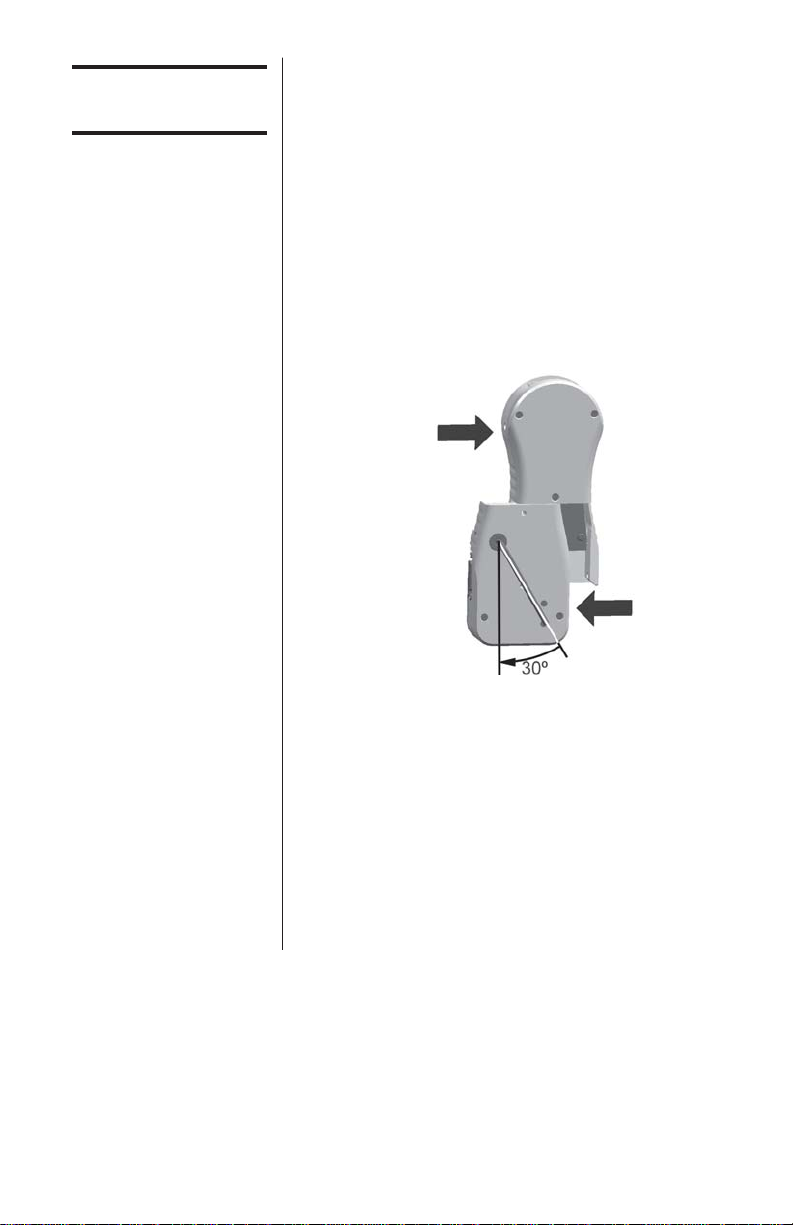
To exchange the cartridge, power down the gauge
and remove it from the test stand if it is fitted to one.
Turn the gauge face down and insert a 3mm Allen key
(supplied) into the boss on the back of the ALC. To
unlock the ALC rotate the boss anti-clockwise with the
Allen key through approximately 30º to release the
spring loaded locking cam. While still holding the
Allen key in position slide the ALC away from the AFG
console to the left. See Figure 5.
Figure 5
Removing ALC
To fit the new ALC, first insert the Allen key into its
boss and rotate the locking cam as above. Slide the
ALC into the AFG console, ensuring that the mating
surfaces are correctly aligned.
Push the ALC firmly home into the AFG console and,
to lock it, tighten the locking cam by rotating the Allen
key clockwise until slight pressure is felt. Take care
not to over tighten the locking cam.
Warning! The AFG must
be powered down when
connecting or discon-
necting smart load
sensors.

Advanced Force Gauge User’s Manual
14
‘Smart’ Sensors
Warning! The AFG must
be powered down when
connecting or discon-
necting smart load
sensors.
Loadcell Diagnostic
Test
Advanced Menu
Options
Navigating the menus
All Advanced Loadcell Cartridges have a 15-pin
‘Smart’ connector port on the right hand side for
interface with Quantrol external ‘Smart’ force and
torque sensors. This allows you to use your existing
AFG console to perform additional tests without the
need for a dedicated instrument.
To connect a ‘Smart’ sensor, power down the gauge
and plug in the ‘Smart’ force or torque sensor to the
15-pin ‘Smart’ port. Power on the AFG. The ‘Smart’
load sensor will be automatically recognized and the
capacity displayed.
If you suspect that your ALC loadcell or ‘Smart’
sensor has sustained an overload it is possible to
check the status of the sensor immediately.
Symptoms of overload may be (a) OL in display (b)
buzzer sound (c) probe not aligned perpendicularly to
gauge (d) load indicator bar present even under zero
load.
See Calibration section of Advanced Menu Options to
check load cell status.
All the features and advanced menu options of the
AFG are also applicable while using the ‘Smart’ range
of peripheral devices.
The AFG Advanced Menus are accessed using the
red text on the keys.
Press and hold the MENU key for approximately 2
seconds to access page 1 of the main menu. To move
between the options listed on the 2 main menu pages,
press UP and DOWN to move the cursor. Press
ENTER to select sub-menus, activate features and
enter values. Within sub-menus UP and DOWN will
also change numerical values. Press ESC to return to
page 1 of the main menu page.
If ALARM is selected in page 1, by pressing ENTER
the status of all the other functions can be seen by
consecutively pressing the MENU key to scroll
through the functions one at a time. Press ESC once
to return to the main menu page and twice to return to
the main display.
An instrument showing
an overload condition
cannot be relied upon to
provide accurate,
repeatable measurement
–consult your Quantrol
distributor.
See the Appendix in the
back of this manual for
flowcharts of all the
menus.
Advanced Force Gauge User’s Manual 15
ALARM
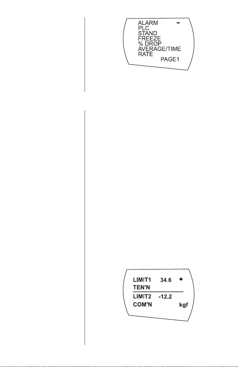
Figure 6
Main Menu
The AFG has an audible and visual alarm feature
which can be set to trigger on pass, fail or sample
break criteria.
To set an alarm, press and hold the MENU key until
page 1 of the main menu appears. The cursor arrow
will point to ALARM. Press the ENTER key.
The display will show ALARM OFF and SET.
Press ENTER to change ALARM OFF to ALARM ON.
Press DOWN to move the arrow cursor to SET and
press ENTER.
The display will now show the two limits LIMIT 1
(lower limit) and LIMIT 2 (upper limit) plus the value
they are set to and whether they are in tension
(TENS’N) or compression (COMP’N). A diamond
cursor will indicate which value is selected. Use UP
and DOWN keys to change the value, press and hold
to scroll values. When the correct value is reached
press ENTER to set LIMIT 1. Repeat procedure for
LIMIT 2.
Figure 7
Menu page 1
ALARM sub-menu 1
ALARM sub-menu 2
The alarm limits are not
active below 1% of the
capacity of the gauge.
Compression limits must
have a negative (-) sign
in front of the number.

Advanced Force Gauge User’s Manual
16
ALARM sub-menu 3 The display shows AUDIBLE, LED and BOTH with the
arrow cursor indicating which feature is selected. This
menu selects how the PASS/FAIL status of a value
will be indicated.
AUDIBLE Only the audible alarm will be activated
when the value is a PASS/FAIL
LED The green and red LED’s will indicate the
PASS /FAIL status.
BOTH Both the LED and the audible alarm will
be activated above.
Use UP and DOWN to move the cursor and press
ENTER to select the desired feature.
The display shows OUT BAND and IN BAND. This
menu selects which values are to be considered.
OUT BAND Any value falling outside the set limits
LIMIT 1 and LIMIT 2
IN BAND Any value falling between the set limits
LIMIT 1 and LIMIT 2
Use UP and DOWN to move the cursor and press
ENTER to select the desired feature.
The display shows PASS and FAIL. This menu sets
the OUT BAND and IN BAND mode.
PASS Values, which fall either OUT BAND (or IN
BAND, if selected), are a PASS
FAIL Values, which fall either OUT BAND (or IN
BAND, if selected), are a FAIL and will
cause an audible beep.
Use UP and DOWN to move the cursor and press
ENTER to select the desired feature.
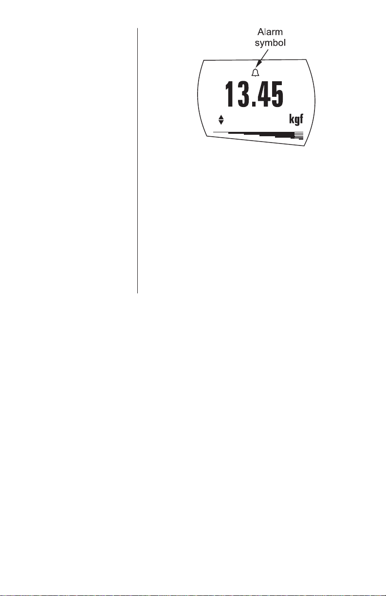
Display is showing sub-menu 1 again (= ALARM ON
and SET). Press ESC to return to main menu and
again to return to main display. The main display will
now show an alarm ‘bell’ symbol indicating the alarm
is turned on. See Figure 8.
ALARM sub-menu 4
ALARM sub-menu 5
Advanced Force Gauge User’s Manual 17
Figure 8
Alarm symbol
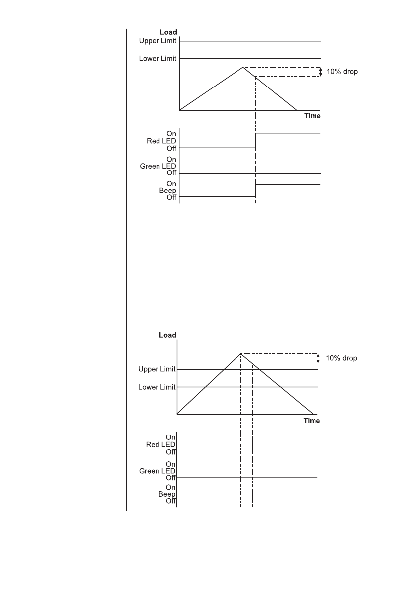
ALARM on break This feature is only activated when the % DROP
feature is used in conjunction with the ALARM
function. The AFG looks for a percentage (of full-
scale) drop from peak load value, set in the % DROP
menu. The alarm can be used to indicate if the break
point falls inside or outside the limits LIMIT 1 and
LIMIT 2 set in the alarm menu (see Examples 1 to 5).
Advanced Force Gauge User’s Manual
18
Example 1
Settings: -
- BOTH LED and audio
alarms are active
- Alarm triggers on OUT
BAND
- Alarm is set to FAIL
- % DROP is 10% of
fullscale (e.g. AFG
100N must register
drop of 10N)
Main display is set to
1st peak tension
screen
Example 2
Settings: -
- BOTH LED and audio
alarms are active
- Alarm triggers on OUT
BAND
- Alarm is set to FAIL
- % DROP is 10% of
fullscale (e.g. AFG
100N must register
drop of 10N)
Main display is set to
1st peak tension
screen
Advanced Force Gauge User’s Manual 19
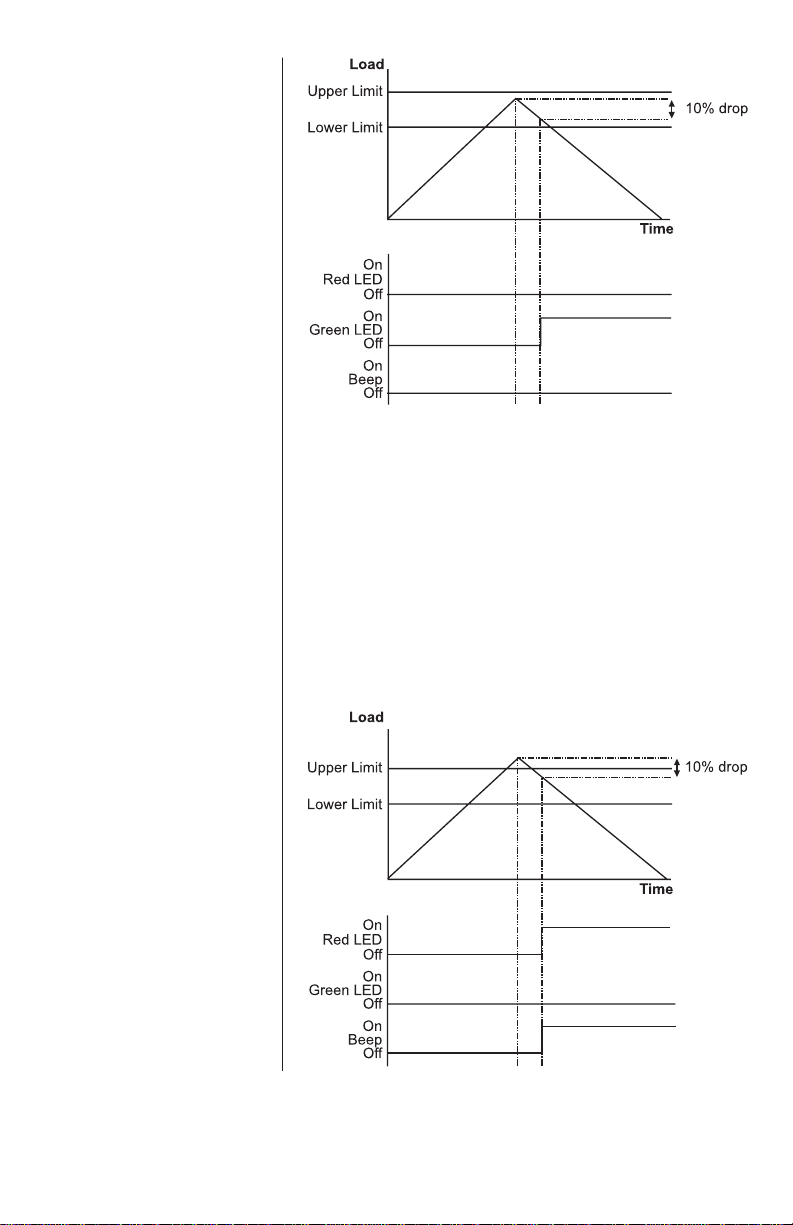
Example 3
Settings: -
- BOTH LED and audio
alarms are active
- Alarm triggers on OUT
BAND
- Alarm is set to FAIL
- % DROP is 10% of
full-scale (e.g. AFG
100N must register
drop of 10N)
Main display is set to
1st peak tension
screen
Example 4
Settings: -
- BOTH LED and audio
alarms are active
- Alarm triggers on OUT
BAND
- Alarm is set to FAIL
- % DROP is 10% of
full-scale (e.g. AFG
100N must register
drop of 10N)
Main display is set to
1st peak tension
screen

Advanced Force Gauge User’s Manual
20
Example 5
Settings: -
- BOTH LED and audio
alarms are active
- Alarm triggers on OUT
BAND
- Alarm is set to FAIL
- % DROP is 10% of
fullscale (e.g. AFG
100N must register
drop of 10N)
Main display is set to
1st peak tension
screen
PLC
(Programmable Limit
Controller)
PLC sub-menu 1
The AFG has a load output signal which may be used
for PLC applications. For PLC applications, this
function requires an external cable with a built-in
solid-state relay – see Specifications for details of the
signal.
To configure the signal output from the AFG, press
and hold the MENU key until page 1 of the main menu
appears. Press DOWN to move the arrow cursor to
PLC and press the ENTER key. The cursor arrow now
points to PLC OFF.
The display will show:
PLC OFF Indicates PLC function status.
RESET When the load limit is reached, the
output signal triggers the relay and
the RESET key must be pressed to
clear the line before starting the next
test.
CONTINUOUS The relay will be activated every time
the load limit is reached and the
output signal will remain on.
PULSE The relay will be activated momen-
tarily when the load limit is reached.
Select the desired function and press the ENTER key.
This manual suits for next models
10
Table of contents
Other Dillon Test Equipment manuals


