HT EQUITEST 5071 User manual

Copyright HT ITALIA 2013 Versione EN 1.00 - 15/01/2013
EQUITEST 5071
User manual


EQUITEST 5071
EN - 1
Table of contents
1.PRECAUTIONS AND SAFETY MEASURES..................................................................2
1.1.Preliminary instructions......................................................................................................... 2
1.2.During use............................................................................................................................. 3
1.3.After use................................................................................................................................ 3
Definition of measurement (overvoltage) category......................................................................... 3
2.GENERAL DESCRIPTION..............................................................................................4
3.PREPARATION FOR USE..............................................................................................4
3.1.Initial checks.......................................................................................................................... 4
3.2.Instrument power supply.......................................................................................................4
3.3.Calibration............................................................................................................................. 4
3.4.Storage.................................................................................................................................. 4
4.INSTRUMENT DESCRIPTION........................................................................................5
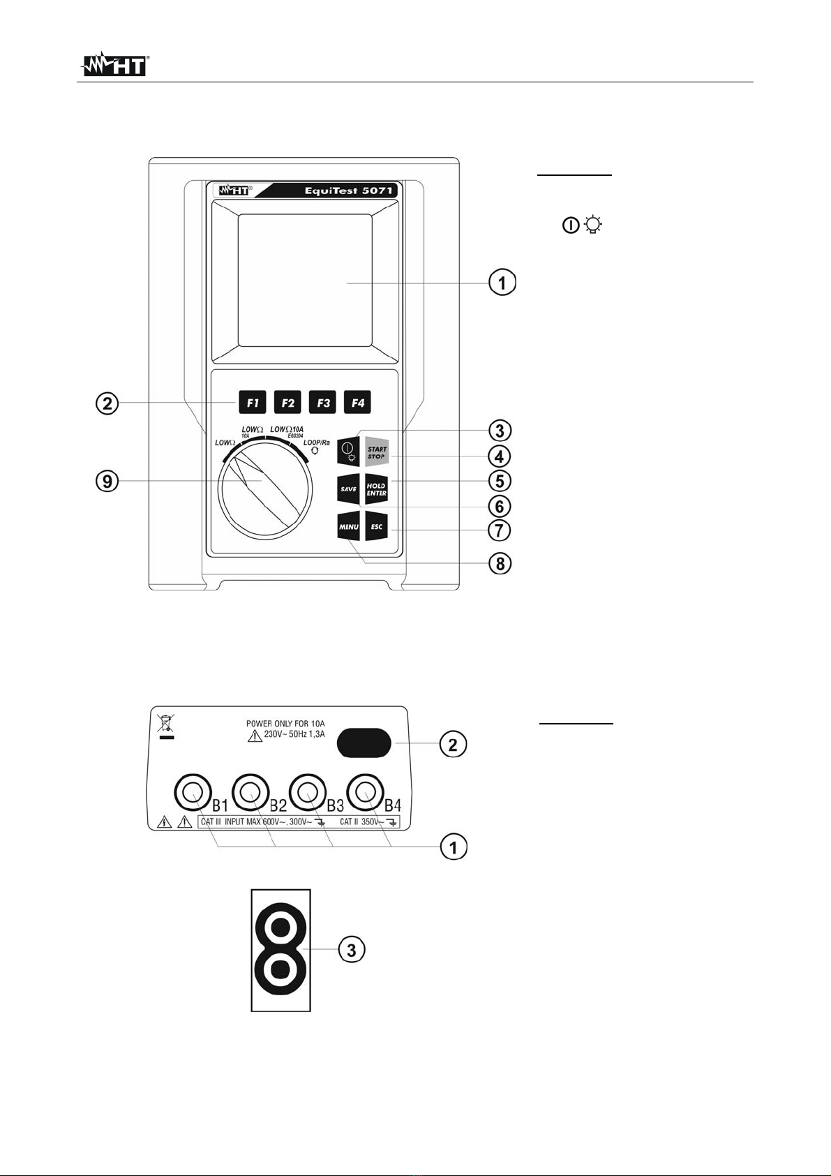
4.1.Front panel............................................................................................................................ 5
4.2.Input and output leads........................................................................................................... 5
4.3.Description of function keys .................................................................................................. 6
4.4.Display description................................................................................................................ 6
4.5.Initial screen.......................................................................................................................... 6
4.6.Backlight................................................................................................................................ 7
5.INITIAL SETTINGS .........................................................................................................7
5.1.Adjusting display contrast...................................................................................................... 7
5.2.Adjusting date and time......................................................................................................... 8
5.3.Language setting................................................................................................................... 8
6.OPERATING INSTRUCTIONS........................................................................................9
6.1.LOW: Continuity of protective conductors with 200mA....................................................... 9
6.1.1.Calibration of measuring cables.................................................................................................. 10
6.1.2.Measuring.................................................................................................................................... 11
6.1.2.1.Anomalous situations in "AUTO", "RT+", "RT-" mode...........................................................................13
6.2.LOW10A: Continuity of protective conductors with 10A................................................... 14
6.2.1.Measuring.................................................................................................................................... 14
6.2.2.Anomalous situations.................................................................................................................. 16
6.3.LOW10AE204: Continuity 10A in compliance with IEC/EN60204-1:2006........................ 17
6.3.1.Measuring.................................................................................................................................... 18
6.3.2.Anomalous situations.................................................................................................................. 20
6.4.LOOP/Ra : Loop impedance, overall earth resistance and phase sequence.................. 21
6.4.1.High-resolution impedance measurement (0.1 m)................................................................... 22
6.4.2."P-N" mode: measurement procedure and results ..................................................................... 22
6.4.3."P-P" mode: measurement procedure and results...................................................................... 24
6.4.4."P-PE" mode: measurement procedure and results................................................................... 25
6.4.5."RA" mode: measurement procedure and results................................................................... 27
6.4.6."" mode: measurement procedure and results ....................................................................... 29
6.4.6.1.Anomalous situations in "P-P", "P-N", "P-PE","RA", " " mode......................................................30
7.OPERATIONS WITH THE MEMORY............................................................................34
7.1.Storage of measurement results......................................................................................... 34
7.2.Recalling and deleting data from the memory..................................................................... 34
8.CONNECTING THE INSTRUMENT TO THE PC..........................................................35
9.MAINTENANCE ............................................................................................................36
9.1.General information............................................................................................................. 36
9.2.Battery replacement............................................................................................................ 36
9.3.Cleaning the instrument ...................................................................................................... 36
9.4.End of life ............................................................................................................................ 36
10.TECHNICAL SPECIFICATIONS.............................................................................37
10.1.Reference standards........................................................................................................... 38
10.2.General characteristics........................................................................................................ 38
10.3.Environmental conditions.................................................................................................... 38
10.4.Accessories......................................................................................................................... 38
11.SERVICE ................................................................................................................39
11.1.Warranty conditions............................................................................................................. 39
11.2.Service ................................................................................................................................ 39

EQUITEST 5071
EN - 2
1. PRECAUTIONS AND SAFETY MEASURES
The instrument has been designed in compliance with Standards IEC/EN61557 and
IEC/EN 61010-1 relevant to electronic measuring instruments.
CAUTION
For your safety and in order to prevent damaging the instrument, please
carefully follow the procedures described in this manual and read all notes
preceded by the symbol with the utmost attention.
Before and after carrying out the measurements, carefully observe the following
instructions:
Do not carry out any voltage or current measurement in humid environments
Do not carry out any measurements in case gas, explosive materials or flammables are
present, or in dusty environments
Avoid contact with the circuit being measured if no measurements are being carried out
Avoid contact with exposed metal parts, unused measuring probes, circuits, etc.
Do not carry out any measurement in case you find anomalies in the instrument such
as deformation, substance leaks, absence of display on the screen, etc.
Pay special attention when measuring voltages higher than 25V in special
environments (such as construction sites, swimming pools, etc.) and 50V in normal
environments, since a risk of electrical shock exists.
Only use original accessories.
In this manual, and on the instrument, the following symbols are used:
CAUTION: observe the instructions given in this manual; improper use could
damage the instrument, its components and create dangerous situations for the
operator.
Presence of dangerous voltage (30V): electrical shock hazard
Double-insulated meter
AC voltage or current
Connection to earth
1.1. PRELIMINARY INSTRUCTIONS
This instrument has been designed for use in environments of pollution degree 2.
The instrument may be used for measuring and verifying the safety of electrical
systems of overvoltage category CAT III 300V (to earth) or CAT II 350V (to earth).
We recommend following the normal safety rules devised to protect the user against
dangerous currents and the instrument against incorrect use.
Only the accessories provided together with the instrument will guarantee safety
standards. If necessary, replace them with identical models.
Do not test circuits exceeding the specified current and voltage limits. Do not perform
any test under environmental conditions exceeding the limits indicated in § 10.3.
Check that the batteries are correctly inserted.
Before connecting the test leads to the circuit to be tested, make sure that the switch is
correctly set.

EQUITEST 5071
EN - 3
1.2. DURING USE
Please carefully read the following recommendations and instructions:
CAUTION
Failure to comply with the caution notes and/or instructions may damage
the instrument and/or its components or be a source of danger for the
operator.
Before activating the rotary switch, disconnect the test leads from the circuit under test.
When the instrument is connected to the circuit under test, never touch any terminal,
even if unused.
Avoid measuring resistance if external voltages are present. Even if the instrument is
protected, excessive voltage could cause damage.
1.3. AFTER USE
When measurements are complete, turn off the instrument by pressing and holding the
ON/OFF key for some seconds.
If the instrument is not to be used for a long time, remove the batteries and follow the
instructions given in § 9.2.
DEFINITION OF MEASUREMENT (OVERVOLTAGE) CATEGORY
Standard “IEC/EN61010-1: Safety requirements for electrical equipment for measurement,
control and laboratory use, Part 1: General requirements” defines what measurement
category, commonly called overvoltage category, is. § 6.7.4: Measured circuits, reads:
Circuits are divided into the following measurement categories:
Measurement category IV is for measurements performed at the source of the low-
voltage installation
Examples are electricity meters and measurements on primary overcurrent protection
devices and ripple control units.
Measurement category III is for measurements performed inside buildings.
Examples are measurements on distribution boards, circuit breakers, wiring, including
cables, bus-bars, junction boxes, switches, socket-outlets in the fixed installation, and
equipment for industrial use and some other equipment, for example, stationary motors
with permanent connection to fixed installation.
Measurement category II is for measurements performed on circuits directly
connected to the low-voltage installation
Examples are measurements on household appliances, portable tools and similar
equipment
Measurement category I is for measurements performed on circuits not directly
connected to MAINS.
Examples are measurements on circuits not derived from MAINS, and specially
protected (internal) MAINS-derived circuits. In the latter case, transient stresses are
variable; for that reason, the standard requires that the transient withstand capability of
the equipment is made known to the user.

EQUITEST 5071
EN - 4
2. GENERAL DESCRIPTION
Instrument EQUITEST 5071 carries out the following measurements:
LOW: Continuity test of protective conductors with test current of 200mA in
compliance with standard IEC/EN61557-4
LOW10A: Continuity test of protective conductors with test current of 10A in
compliance with standard IEC/EN60439-1
LOW10AE60204: Continuity test of protective conductors with test current of 10A in
compliance with standard IEC/EN60204-1:2006.
LOOP/Ra : measurement of line impedance and fault loop impedance with
calculation of the assumed short-circuit current, also with high
resolution (0.1m) with optional accessory IMP57 / measurement of
overall earth resistance without causing the differential protections’
tripping (function RA) / phase rotation.
3. PREPARATION FOR USE
3.1. INITIAL CHECKS
Before shipping, the instrument has been checked from an electric as well as mechanical
point of view. All possible precautions have been taken so that the instrument is delivered
undamaged.
However, we recommend rapidly checking it to detect any damage possibly suffered
during transport. In case anomalies are found, immediately contact the Dealer.
We also recommend checking that the packaging contains all components indicated in §
10.4. In case of discrepancy, please contact the Dealer. In case the instrument should be
returned, please follow the instructions given in § 11.
3.2. INSTRUMENT POWER SUPPLY
The instrument is supplied by six 1.5V alkaline batteries type LR6 AA AM3 MN 1500, not
included in the package. For battery installation, follow the instructions given in § 9.2.
CAUTION
The instrument AUTOMATICALLY turns OFF display backlight after
approximately 5 seconds.
In order to extend the battery life, in case battery voltage is too low, the
instrument deactivates display backlighting.
3.3. CALIBRATION
The instrument has the technical specifications described in this manual. Its performance
is guaranteed for 12 months from the date of purchase.
3.4. STORAGE
In order to guarantee precise measurement, after a long storage time under extreme
environmental conditions, wait for the instrument to come back to normal condition (see
§ 10.3)

EQUITEST 5071
EN - 5
4. INSTRUMENT DESCRIPTION
4.1. FRONT PANEL
CAPTION:
1. LCD display
2. F1, F2, F3, F4 keys
3. /key
4. START/STOP key
5. HOLD/ENTER key
6. SAVE key
7. ESC key
8. MENU key
9. Rotary selector switch
Fig. 1: Description of the instrument’s front panel
4.2. INPUT AND OUTPUT LEADS
CAPTION:
1. B1, B2, B3, B4 inputs
2. Input for external
230V/50Hz power supply
for functions LOW10A
and LOW10AE60204
3. Optical serial output for
PC connection
Fig. 2: Description of the instrument’s inputs and outputs

EQUITEST 5071
EN - 6
4.3. DESCRIPTION OF FUNCTION KEYS
Key Description
/Key to switch on/off the instrument. Press and hold the key for
some seconds to turn off the instrument. Shortly press this key
to activate display backlighting.
F1, F2, F3, F4 Keys for programming the internal parameters associated with
the functions of the instrument.
START/STOP Key for starting measuring. STOP function not enabled.
SAVE Key for saving measurement results.
HOLD/ENTER ENTER key to confirm the parameters set within the general
menu of the instrument. HOLD function not enabled.
MENU Key to access the instrument’s general menu.
ESC Key to quit the selected mode shown on the display.
4.4. DISPLAY DESCRIPTION
The display is a graphic module with a resolution of 128 x 128 dots. The first line of the
display shows the instrument’s date and time. In the top right-hand corner of the display
there is the battery charge indicator.
LOW30.11.12
----
R+ R-
--------
---mA ---mA
AUTO 0.11
FUNC CAL
For the sake of brevity, these symbols will be omitted in the following screenshots of this
manual.
4.5. INITIAL SCREEN
When turning on the instrument with the /key, the following screen appears for a few
seconds:
HT5071
HT
SN:12345678 V: 1.59
Baud Rate 57600
CALIBRATION DATE:
30.11.12
It contains (further to the name of the Manufacturer and to
the instrument model):
The serial number (SN:) of the instrument.
The firmware version (V:) in the instrument's memory.
The date of the last instrument calibration
(CALIBRATION DATE).
The serial transmission speed (Baud Rate).
Press ESC to exit this screen.

EQUITEST 5071
EN - 7
4.6. BACKLIGHT
During instrument operation, a further short pressing of the /key turns on the display’s
backlighting. In order to save battery efficiency, backlighting automatically turns off after
approx. 5 seconds. A frequent use of backlighting reduces the batteries’ life.
5. INITIAL SETTINGS
When pressing the MENU key, the display shows the following screen, which allows
accessing the General Menu:
GENERAL MENU
SAFETY TEST MEMORY
CONTRAST
DATE&TIME
LANGUAGE
The following items are available:
Safety Test Memory memory area for saving measuring results.
Contrast function to adjust display contrast.
Date&Time function to adjust system date/time.
Language function to select system language.
5.1. ADJUSTING DISPLAY CONTRAST
Proceed as follows:
1. Press the MENU key with the selector switch in any position to enter the General
Menu.
2. Use the F1 key to move the cursor to “CONTRAST”. Confirm with ENTER. The
following screen appears on the display:
CONTRAST
CONTRAST
35%
+ -
3. Use the F3 and F4 keys to set the desired percentage value.
4. Press the ENTER key to confirm. The settings made shall remain valid also after
switching off the instrument.
5. Press the ESC key to exit without saving.

EQUITEST 5071
EN - 8
5.2. ADJUSTING DATE AND TIME
Proceed as follows:
1. Press the MENU key with the selector switch in any position to enter the General
Menu.
2. Use the F1 key to move the cursor to “DATE&TIME”. Confirm with ENTER. The
following screen appears on the display:
DATE&TIME
25 . 08 . 12
15 : 25 : 00
+ -
3. Use the F1 and F2 keys to alternately select the date and time fields. The selected field
appears with a black background. The date is expressed with format: “gg.mm.aa” while
time is expressed in format: “hh:mm:ss”
4. Use the F3 and F4 keys to increase or decrease the value of date/time.
5. Press the ENTER key to confirm. The settings made shall remain valid also after
switching off the instrument.
6. Press the ESC key to exit without saving.
5.3. LANGUAGE SETTING
Proceed as follows:
1. Press the MENU key with the selector switch in any position to enter the General
Menu.
2. Use the F1 key to move the cursor to “LANGUAGE”. Confirm with ENTER. The
following screen appears on the display:
LANGUAGE
ITALIAN
ENGLISH
SPANISH
GERMAN
FRENCH
3. Use the F1 and F2 keys to select the desired language among those available.
4. Press the ENTER key to confirm. The settings made shall remain valid also after
switching off the instrument.
5. Press the ESC key to exit without saving.

EQUITEST 5071
EN - 9
6. OPERATING INSTRUCTIONS
6.1. LOW: CONTINUITY OF PROTECTIVE CONDUCTORS WITH 200mA
Measurement is carried out in compliance with standard IEC/EN61557-4.
CAUTION
Before carrying out the continuity test, make sure there is no voltage at the
ends of the conductor to be analyzed.
Turn the rotary switch to LOW.
With the F1 key it is possible to select one of the following measuring modes
(which cyclically appear when pressing the key):
“AUTO” mode (the instrument carries out two measurements with
inverted polarity and displays their average value). Recommended mode
for continuity test
“RT+” mode (measurement with positive polarity and with the possibility
of setting a duration time for testing). In this case, the operator may set a
sufficiently long measuring time to be able to move the protective
conductors while the instrument is carrying out the test, in order to find
out a possible bad connection.
“RT-” mode (measurement with negative polarity and with the possibility
of setting a duration time for testing). In this case, the operator may set a
sufficiently long measuring time to be able to move the protective
conductors while the instrument is carrying out the test, in order to find
out a possible bad connection.
With the F2 key it is possible to select the “CAL“ mode (compensation of the
resistance of the cables used for measuring).
CAUTION
Continuity test is carried out by applying a current higher than 200mA in
case resistance does not exceed 5(including the measuring cables’
resistance saved as offset value in the instrument after carrying out the
calibration procedure). For higher resistance values, the instrument carries
out the test with a current lower than 200mA.

EQUITEST 5071
EN - 10
6.1.1. Calibration of measuring cables
1. Insert the black cable and the blue cable into the relevant input terminals B1 and B4 of
the instrument.
Fig. 3: Terminal connection during calibration procedure
2. If, for the measurement to be carried out, the length of the cables provided should be
insufficient, extend the blue cable.
3. Insert two alligator clips into the cable terminals.
4. Short-circuit the measuring cables’ ends, taking care that the conductive parts of the
alligator clips have good contact (see Fig. 3)
5. Press the F2 key. The instrument calibrates.
CAUTION
Never disconnect the terminals from the measuring points when the
instrument shows the message "MEASURING…".
LOW
30.11.12
----
R+ R-
--------
---mA ---mA
A
UTO 0.11
This numerical
value indicates
that calibration has
been carried out
FUNC CAL
6. At measurement end, the instrument gives out a double sound, to indicate that
calibration has been correctly carried out. The value of calibration is updated and
displayed above the F2 key. This value shall remain saved also after the instrument
has been switched off.
CAUTION
The instrument calibrates the measuring cables only if their resistance is
lower than 5
Before carrying out any measurement, always make sure that calibration
is referred to the cables currently used. In a continuity test, if the purified
resistance value (i.e. the value of resistance minus the calibration offset
value) is negative, the symbol “CAL” flashes on the display.
7. To delete the calibration parameter it is necessary to carry out a calibration
procedure with a lead resistance higher than 5(e.g. with open leads). When
carrying out a deletion, the symbol “- - -“ is shown on the display above the F2 key.

EQUITEST 5071
EN - 11
6.1.2. Measuring
1. Select the desired mode using the F1 key.
2. Insert the black cable and the blue cable into the relevant input terminals B1 and B4 of
the instrument:
Fig. 4: Instrument connection for LOWtest
3. If, for the measurement to be carried out, the length of the cables provided should be
insufficient, extend the blue cable.
4. Insert two alligator clips into the cable terminals.
5. Short-circuit the measuring cables’ ends, taking care that the conductive parts of the
alligator clips have good contact. Press the START/STOP key. If the instrument
shows a resistance value different from 0,00 repeat the calibration operation (see
§ 6.1.1)
6. Connect the instrument terminals to the ends of the conductor whose continuity you
want to test (see Fig. 4)
7. If mode "RT+" or "RT-" is selected, use the F3, F4 keys to set the test time.
8. Press the START/STOP key. The instrument carries out the measurement. In "RT+" or
"RT-" mode, press the START/STOP key again to stop the test.
CAUTION
When message "MEASURING…" is displayed, this indicates that the
instrument is carrying out the test. Never disconnect the instrument’s leads
during this phase.

EQUITEST 5071
EN - 12
"AUTO" mode results
A
t the end of the test, in
case the average value
of resistance Ravg
measured is lower than
5, the instrument gives
out a double sound to
signal the positive
result of the test. The
following screen
appears on the display:
LOW
30.11.12
A
verage value of
resistance Ravg
1.05
R+ R-
1.071.03
219mA 219mA
AUTO 0.11
Value of test current
FUNC CAL
The results can be saved by pressing the SAVE key twice (see § 7.1).
"RT+" or “RT-" mode results
During the test, an
audible beep sounds in
case the measured
resistance value exceeds
99.9.
If, at the end of the test,
the maximum RT+ or RT-
resistance value
measured is lower than
5, the instrument gives
out a double sound to
signal the positive
result of the test. The
following screen appears
on the display:
LOW
30.11.12
Maximum value of
resistance measured
during test
1.07
219mA
RT+ 0.11
T
IME: 10s
Test current
Duration of test
FUNC CAL
The results can be saved by pressing the SAVE key twice (see § 7.1).

EQUITEST 5071
EN - 13
6.1.2.1. Anomalous situations in "AUTO", "RT+", "RT-" mode
If the instrument detects
a voltage higher than
approx. 15V at the input
terminals, the message
to the side appears on
the display.
LOW
30.11.12
-.- -
R+ R-
-.---.--
---mA ---mA
VOLT IN INPUT
AUTO 0.11
The test cannot be
carried out because
voltage has been
detected at the
instrument’s inputs
FUNC CAL
If the instrument detects
that:
RCALIBRATION > RMEASURED
the message to the side
appears on the display.
LOW
30.11.12
0.00
R+ R-
0.000.00
219mA 219mA
CAL > RES
AUTO 0.11
CAUTION:
RCALIBRATION > RMEASURED
FUNC CAL
PREVIOUS RESULTS CANNOT BE SAVED.
In case a resistance
higher or equal to 5
but lower than 99,9is
detected, at the end of
the test the instrument
gives out a long sound
and the following screen
appears on the display.
LOW
30.11.12
5.17
R+ R-
5.175.17
209mA 209mA
AUTO 0.11
Resistance higher than 5
Test current
FUNC CAL
The results can be saved by pressing the SAVE key twice (see § 7.1).
In case a resistance
higher than 99,9is
detected, at the end of
the test the instrument
gives out a long sound
and the following screen
appears on the display.
LOW
05.06.12
Resistance with a value
higher than 99.9
> 99.9
R+ R-
-.---.--
---mA ---mA
AUTO 0.11
CAUTION: Resistance
value out of range
FUNC CAL
The results can be saved by pressing the SAVE key twice (see § 7.1).

EQUITEST 5071
EN - 14
6.2. LOW10A: CONTINUITY OF PROTECTIVE CONDUCTORS WITH 10A
Measurement is carried out in compliance with standards IEC/EN60439-1.
Measurement is carried out by voltammetric method with 4 wires. Therefore, the calculated
value is not influenced by the value of resistance of the measuring cables, so it is not
necessary to carry out any preventive calibration of the cables used for measuring (unlike
with function LOW).
CAUTION
Before carrying out the continuity test, make sure there is no voltage at the
ends of the conductor to be analyzed.
Measurement may be influenced by parallel impedance of additional
circuits or by transient currents. Make sure none of these parasite
elements is present before measuring and always keep test cables
outstretched in order to prevent “coil effects”.
CAUTION
The instrument performs the test with a current 10A only if resistance is
lower than approx. 0.45.
6.2.1. Measuring
1. Turn the rotary switch to LOW10A. The following screen appears on the display:
LOW 10A 30.11.12
-----
----A
RLIM: 0.100
2. Use the F3 and F4 keys to set the maximum limit threshold RLIM for measurement in
range 0.0010.999. Keep the function keys pressed for a quick setting of the
desired value
3. Supply the instrument by connecting it to the 230V/50Hz electric mains (see Fig. 2 –
position 2) by means of the cable provided.
4. Connect the connectors of the measuring cables C7000 provided to the instrument’s
input terminals B1 (Black), B2 (Red), B3 (Red), B4 (Black) and the alligator clips to the
item to be tested as indicated in Fig. 5

EQUITEST 5071
EN - 15
Fig. 5: Instrument connection for LOW10A test
5. Press the START key. The instrument starts testing.
CAUTION
When message "MEASURING…" is displayed, this indicates that the
instrument is carrying out the test. Never disconnect the instrument’s leads
during this phase.
A
t the end of the test, the
instrument gives out a
double sound to indicate
that test has been
correctly performed and
the following screen
appears on the display.
LOW
10A 31.11.12
0.107
13.4A
RLIM:0.100
Measured resistance
Test current
6. The displayed results can be saved by pressing the SAVE key twice (see § 7.1).

EQUITEST 5071
EN - 16
6.2.2. Anomalous situations
If the instrument does not
detect any power supply
at connector "230V 50Hz",
it displays the message
reported to the side.
LOW
10A 31.11.12
-----
----A
NO POWER SUPPLY
R
LIM=0.100
If the instrument detects
a resistance higher than
the limit set, it gives out
a long sound and the
following screen
appears on the display.
LOW
10A 31.11.12 Symbol indicates a
resistance higher than the
limit set.
0.323
9.12A
RLIM=0.100
Test current
The displayed results can be saved by pressing the SAVE key twice (see § 7.1).
If the instrument detects
a resistance higher than
the maximum
measurable value, it
gives out a long sound
and the following screen
appears on the display.
LOW
10A 31.11.12 Symbol ">" indicates a
resistance higher than the
maximum measurable
value.
>0.999
9.12A
RLIM=0.100
Test current
The displayed results can be saved by pressing the SAVE key twice (see § 7.1)

EQUITEST 5071
EN - 17
6.3. LOW10AE204: CONTINUITY 10A IN COMPLIANCE WITH IEC/EN60204-
1:2006
Measurement is carried out in compliance with standard IEC/EN60204-1:2006, which
states that measurement result must be compatible with the protective conductor’s length,
section and material.
The instrument evaluates the limit threshold of measured resistance according to the
following formula:
S
L
R
lim
in which:
L = length in mof the protective conductors being tested, decided by the user
according to design calculations;
S= section in mm2of the protective conductor being tested;
= resistivity of copper set to the standard average value of 0.017mm2/m.
Measurement is carried out by voltammetric method with 4 wires. Therefore, the calculated
value is not influenced by the value of resistance of the measuring cables, so it is not
necessary to carry out any preventive calibration of the cables used for measuring (unlike
with function LOW).
CAUTION
Before carrying out the continuity test, make sure there is no voltage at the
ends of the conductor to be analyzed.
Measurement may be influenced by parallel impedance of additional
circuits or by transient currents. Make sure none of these parasite
elements is present before measuring and always keep test cables
outstretched in order to prevent “coil effects”.
CAUTION
The instrument performs the test with a current 10A only if resistance is
lower than approx. 0.45.

EQUITEST 5071
EN - 18
6.3.1. Measuring
1. Turn the rotary switch to LOW10AE204. The following screen appears on the display:
LOW10AE204 30.11.12
-----
----A
LEN: 10.0 SEC: 4.0
2. Use the F1 and F2 keys to set the length in range 0.1m 999.9m and keys F3 and F4
to set the section of the protective conductor being tested, selecting the values 0.5, 1,
1.5, 2.5, 4, 6, 10, 16mm2. Keep the function keys pressed for a quick setting of the
desired values
3. Supply the instrument by connecting it to the 230V/50Hz electric mains (see Fig. 2 –
position 2) by means of the cable supplied.
4. Connect the connectors of the measuring cables C7000 provided to the instrument’s
input terminals B1 (Black), B2 (Red), B3 (Red), B4 (Black) and the alligator clips to the
item to be tested as indicated in Fig. 6
Fig. 6: Instrument connection for LOW10AE204 test
Table of contents
Other HT Test Equipment manuals
Popular Test Equipment manuals by other brands

Multimetrix
Multimetrix VT 35 user manual

Megger
Megger DET Series user guide

Fluke Calibration
Fluke Calibration 5322A Operator's manual

Keysight Technologies
Keysight Technologies B1542A Pulsed IV Package user guide

Vanguard Instruments Company
Vanguard Instruments Company EZCT-2000C user manual

EXFO
EXFO LETP-700 Series manual