sotecc connectBOX User manual

Einbauanleitung Haubenblitzer
Installation instructions
+ connectBOX
DE Seite 1-9 EN page 10-18
Version
DE/EN 2.2
Herausgeber
SOTECC GmbH, Armbruststr. 75, 73230 Kirchheim unter Teck
Kontakt

© 2023 SOTECC GmbH Alle Rechte vorbehalten. / All rights reserved. Rev. 2.1
Einbauanleitung Haubenblitzer
Installation instructions
2
Inhaltsverzeichnis
Inhaltsverzeichnis................................................................................................................................... 2
1 Wichtige Informationen .................................................................................................................. 3
2 Einbauanleitung............................................................................................................................... 4
2.1 Auflistung der benötigten Werkzeuge und Materialien ......................................................... 4
2.2 Ankleben des Haubenblitzers mit der beigelegten Schablone................................................ 4
2.3 Installation Stand-alone .......................................................................................................... 6
2.4 Installation connectBOX .......................................................................................................... 6
2.5 Verkabeln ................................................................................................................................ 7
2.6 Ein / Aus Schalter..................................................................................................................... 8
3 Troubleshooting .............................................................................................................................. 8
4 Funktionstest / Überprüfen der Verbindung zum FLARM® ............................................................ 8
5 Kontakt ............................................................................................................................................ 9
English
6 Installation instructions................................................................................................................. 10
6.1 Important Information .......................................................................................................... 10
6.2 List of tools and materials required ...................................................................................... 11
6.3 Glueing the canopy flasher with the enclosed template ...................................................... 12
6.4 Installation Stand-alone ........................................................................................................ 14
6.5 Installation connectBOX ........................................................................................................ 14
6.6 Wiring .................................................................................................................................... 14
6.7 ON / OFF Switch .................................................................................................................... 15
7 Troubleshooting ............................................................................................................................ 16
8 Function test / Checking the connection to FLARM®.................................................................... 16
This section can be found in our manual. ............................................................................................ 16
9 Contact .......................................................................................................................................... 16
10 Anhang / Appendix.................................................................................................................... 17
10.1 Verkabelung mit connectBOX / Wiring with connectBOX..................................................... 17
10.2 Verkabelung Haubenblitzer / Wiring canopy flash ............................................................... 18

© 2023 SOTECC GmbH Alle Rechte vorbehalten. / All rights reserved. Rev. 2.1
Einbauanleitung Haubenblitzer
Installation instructions
3
1Wichtige Informationen
Der Einbau und die Benutzung des Haubenblitzers erfolgt auf eigene Verantwortung, muss mit dem
für das Flugzeug zuständigen Prüfer abgesprochen sein und darf nur in Segelflugzeugen unter VFR-
Sichtflugbedingungen verwendet werden. Eine andere Verwendung ist nicht zulässig. Bei Einbau,
Betrieb und Prüfung gelten die jeweiligen Gesetze des Landes, in dem das System eingebaut und/oder
betrieben wird. Arbeiten an der Avionik können bei unsachgemäßer Ausführung zum Ausfall dieser
führen. Der Haubenblitzer ist ein System zur Verbesserung der Sichtbarkeit durch andere
Luftverkehrsteilnehmer im Luftraum. Es dient lediglich als Unterstützung und ersetzt unter keinen
Umständen eine aktive Luftraumbeobachtung durch den verantwortlichen Piloten. Das
Haubenblitzersystem kann nicht jede Kollision verhindern. Die SOTECC GmbH trägt keine
Verantwortung für eigenständigen Einbau, Änderungen oder Reparaturen, Missbrauch oder Unfälle.
Die SOTECC GmbH behält sich das Recht vor, Änderungen bzgl. der technischen Daten und Funktionen
ohne vorherige Ankündigung vorzunehmen. SOTECC übernimmt keine Haftung bei offensichtlichen
Druck- und Satzfehlern.
Dieses Einbauanleitung beinhaltet Informationen zum Einbau. Details zum Betrieb befinden sich im
Handbuch.
Vorsicht vor optischer Strahlung!
Handhabung am Boden: Nicht direkt in das Blitzlicht blicken!
Kontakt mit Wasser unbedingt vermeiden!
Die Einbauanleitung wird laufend ergänzt. Bitte vor dem Einbau die aktuellste
Version herunterladen: https://sotecc.de/downloads/
© 2023 SOTECC GmbH Alle Rechte vorbehalten. / All rights reserved. Rev. 2.1
Einbauanleitung Haubenblitzer
Installation instructions
4
2Einbauanleitung
2.1 Auflistung der benötigten Werkzeuge und Materialien
-Cutter
-Seitenschneider
-Kabelbinder
-Dünner Faden oder schmales Klebeband
-Schaumreiniger/ Reinigungsmittel für die Haube
-6mm Bohrer
Vor Einbau die Schaumbänder auf dem Steg des Haubenblitzers auf korrekten Sitz
prüfen (diese können durch den Transport verrutschen bzw. sich ablösen). 3M-
Klebestreifen zum Fixieren an der Haube auf Druckstellen prüfen.
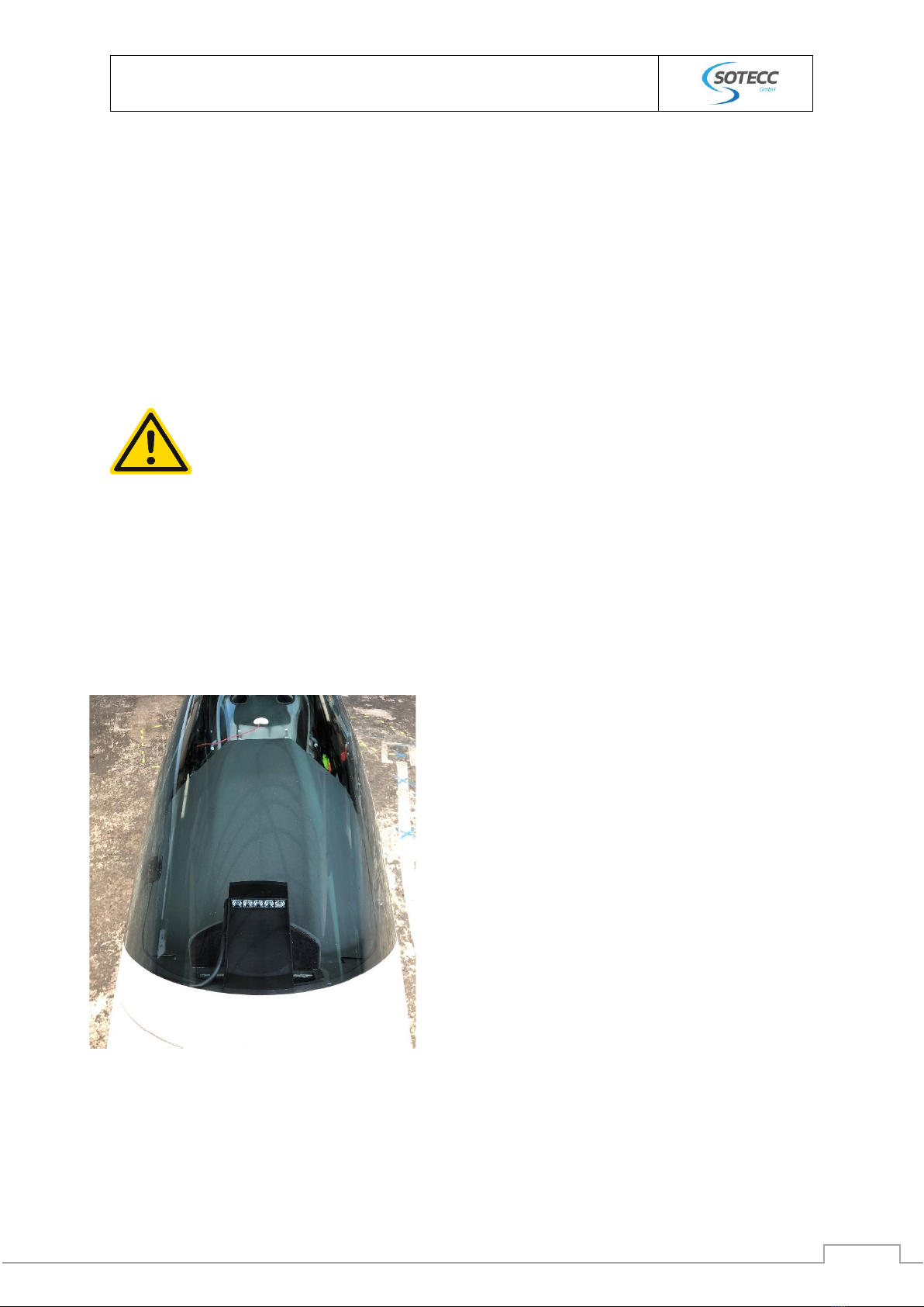
2.2 Ankleben des Haubenblitzers mit der beigelegten Schablone
Dazu mithilfe eines Klebebands oder eines Fadens die
Mitte der Haube bestimmen.
Achtung: Der Faden sitzt nicht immer genau in der
Mitte!)
Tipp: Aus mind. 2-3m Entfernung die Position des
angebrachten Klebebands/Fadens kontrollieren.

© 2023 SOTECC GmbH Alle Rechte vorbehalten. / All rights reserved. Rev. 2.1
Einbauanleitung Haubenblitzer
Installation instructions
5
Die vorderen Abstandshalter der Schablone müssen ca.
1mm hinter der Lackkante (Richtung Leitwerk) platziert
werden.
Verschiedene Einbaubeispiele finden sich hier
(https://einbau.sotecc.de). Das Passwort befindet sich
im beigefügten Begleitschreiben.
Vor dem Ankleben des Haubenblitzers die Haube
gründlich mit geeignetem Reinigungsmittel putzen.
Die Schutzfolien der 3M- Klebesteifen vorsichtig an
einer Ecke mit einem Cutter Messer oder Ähnlichem
ablösen.
Beim Ansetzen des Blitzers an der Haube ist darauf zu achten, dass dieser nicht wieder
angehoben wird, sobald die Klebefläche einmal mit der Haube in Berührung kam.
Haubenblitzer hinten leicht nach unten kippen, dass nur
der vodere Klebestreifen die Haube berührt. Dann von
vorne beginnend die Klebefläche vorsichtig andrücken,
so dass keine Luftblasen entstehen. Abschließend alles
kräftig andrücken.

© 2023 SOTECC GmbH Alle Rechte vorbehalten. / All rights reserved. Rev. 2.1
Einbauanleitung Haubenblitzer
Installation instructions
6
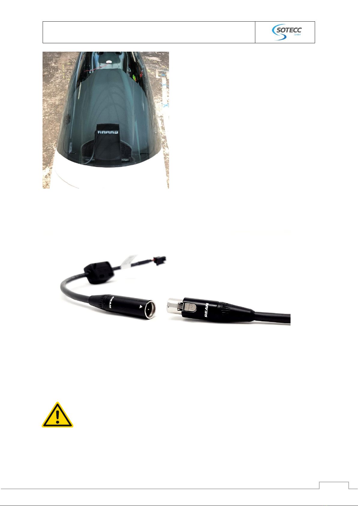
2.3 Installation Stand-alone
Mitgeliefertes Verbindungskabel am 4-poligen Stecker des Haubenkontakt Gegenstücks einstecken
und weiter zu Ein/ Aus Schalter
2.4 Installation connectBOX
Einen geeigneten Platz für die connectBOX hinter dem Instrumentenbrett ausfindig machen ggf.
verschrauben oder mit Klett anbringen. Bestenfalls so, dass alle Ports gut zugänglich sind.
Je nach Flugzeugtyp das Kabel an passender Stelle unter die Abedeckung führen und mit der Klebeschelle
fixieren. Das Gegenstück der Schnelltrennstelle mit dem Haubenblitzer verbinden.
Haubennotabwurf: Die Schnelltrennstelle hat keine Verriegelung und darf nicht
verklebt oder gesichert werden.
© 2023 SOTECC GmbH Alle Rechte vorbehalten. / All rights reserved. Rev. 2.1
Einbauanleitung Haubenblitzer
Installation instructions
7
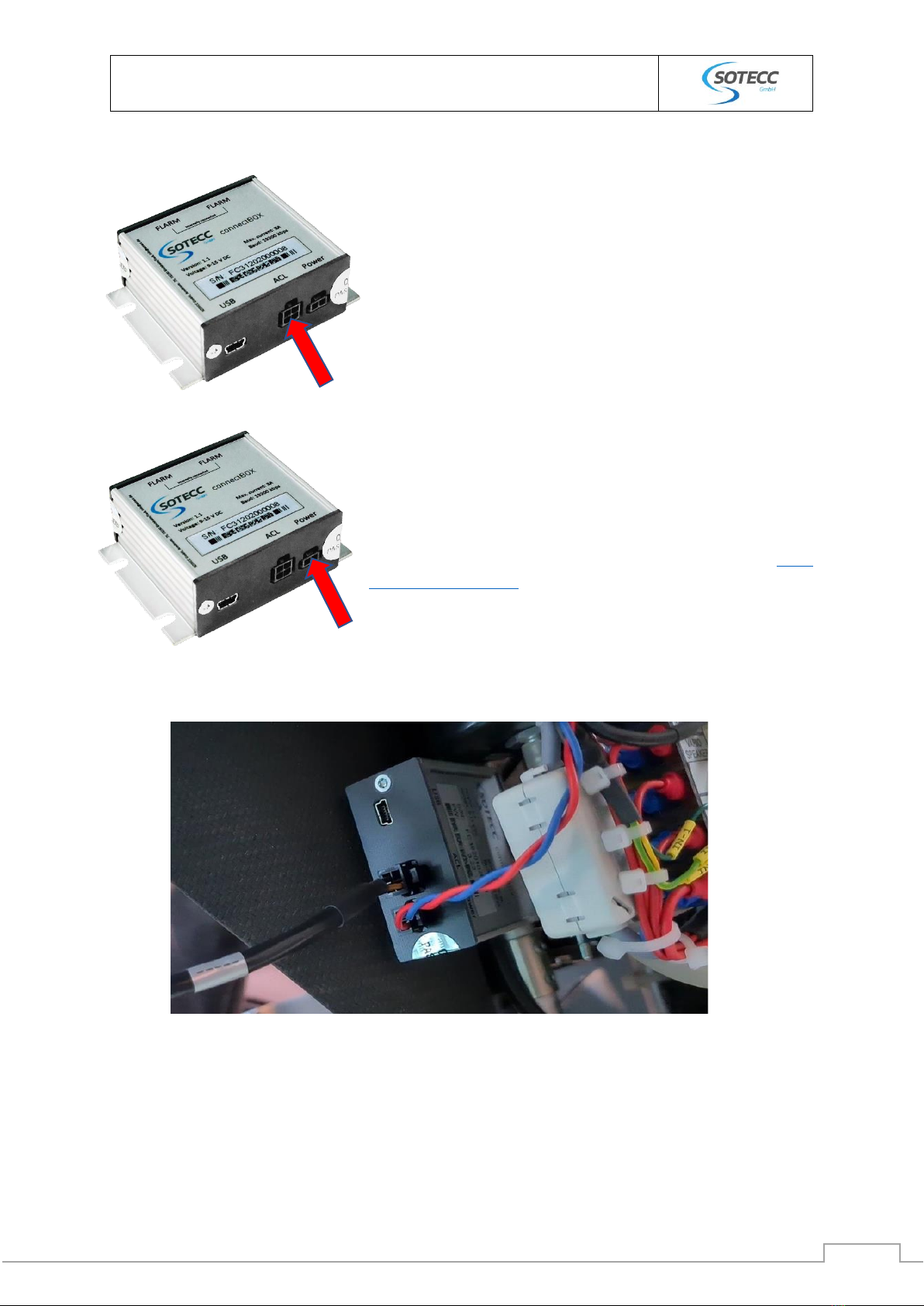
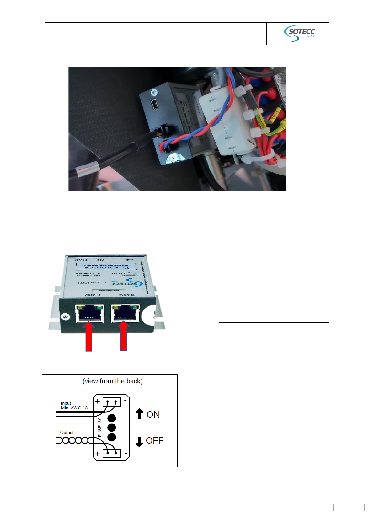
2.5 Verkabeln
Das 4-polige Kabel des Gegenstücks (in der I-Brett Abdeckung,
siehe Arbeitsschritt 4, letztes Bild) in den ACL-Steckplatz der
connectBOX stecken.
Die ConnectBOX über die mitgelieferte Sicherungs/Schalter
Kombi mit dem rot/blau verdrehten 2-poligen Kabel anschließen
(Power-Steckplatz), ggf. Kabellänge anpassen. Den Schalter
anschließend mit einen freien und geeigneten Steckplatz des
Flugzeug Bordnetz verbinden. Detaillierte Übersicht: siehe
Anhang (Verkabelung).
Kabel zum Haubenblitzer oben (ACL), Verbindung zum Bordnetz unten (Power).

© 2023 SOTECC GmbH Alle Rechte vorbehalten. / All rights reserved. Rev. 2.1
Einbauanleitung Haubenblitzer
Installation instructions
8
Abschließend mit RJ45 oder RJ12 Kabel das FLARM® mit
der connectBOX verbinden. Es können beide Anschlüsse
verwendet werden. Falls kein weiteres Gerät
angeschlossen wird, welches Flarmdaten benötigt,
bleibt ein Anschluss frei. Die beiden RJ Ports der
connectBOX sind intern miteinander verbunden,
dadurch kann diese gleichzeitig auch als Splitter (zum
Durchschleifen) verwendet werden. Die Belegung der
Pins entspricht den „IGC GNSS FR Specifications“. Es
können 8-polige (RJ45) oder 6-polige (RJ12) Stecker
ohne Einschränkung verwendet werden.
2.6 Ein / Aus Schalter
3Troubleshooting
•Problem: Der Abstand zwischen den Kontakten am Haubenkontakt ist zu groß und der
Haubenblitzer bekommt keinen Strom.
oLösungsansatz: Kontrollieren, ob der Kontakt wie in Abschnitt „Einsetzen des
Gegenstückes in die Instrumentenbrettabdeckung“ beschrieben, eingebaut worden
ist. Der rumpfseitige Kontakt mit Kabel muss von außen auf der Abdeckung anliegen.
•Problem: Der Haubenblitzer ist am Boden dauerhaft aktiviert.
oLösungsansatz: Bei fehlendem GPS Signal z.B. in der Halle, wird der Haubenblitzer
aktiviert. Diese Funktion kann deaktiviert werden. Details dazu im Handbuch.
4Funktionstest / Überprüfen der Verbindung zum FLARM®
Dieser Abschnitt befindet sich in unserem Handbuch.
An geeigneter Stelle im I-Brett ein 6mm Loch bohren. Kabel
ablängen und am Schalter anschließen. Polarität am Schalter
beachten. Plus+ (rotes Kabel) auf der linken Seite
anschließen. Wir empfehlen die Verwendung von
Aderendhülsen.
Schalter verschrauben und Beschriftung anbringen.

© 2023 SOTECC GmbH Alle Rechte vorbehalten. / All rights reserved. Rev. 2.1
Einbauanleitung Haubenblitzer
Installation instructions
10
6Installation instructions
6.1 Important Information
The installation and use of the canopy flasher is at the pilot's own risk, must be agreed with the
inspector responsible for the glider and may only be used in gliders under VFR visual flight
conditions. Any other use is not permitted. Installation, operation and testing are subject to the laws
of the country in which the system is installed and/or operated. Work on the avionics may lead to
failure of the avionics if not carried out correctly. The canopy flasher is a system to improve visibility
by other air traffic participants in the airspace. It serves only as a support and under no
circumstances replaces an active airspace observation by the pilot in command. The canopy flasher
system cannot prevent every collision. SOTECC GmbH does not bear any responsibility for
independent installation, modifications or repairs, misuse or accidents.
SOTECC GmbH reserves the right to make changes to the technical data and functions without prior
notice. SOTECC accepts no liability for obvious printing and typesetting errors.
This installation manual contains information on installation. Details on operation can be found in the
manual.
Beware of optical radiation!
Handling on the ground: Do not look directly into the flash!
Avoid contact with water at all costs!
The manual is continuously supplemented. Please download the latest version
before installation: https://sotecc.de/downloads/
© 2023 SOTECC GmbH Alle Rechte vorbehalten. / All rights reserved. Rev. 2.1
Einbauanleitung Haubenblitzer
Installation instructions
11
6.2 List of tools and materials required
- cutter
- Side cutter
- Cable tie
- Thin thread or narrow adhesive tape
- Foam cleaner/cleaning agent for the hood
- 6mm drill bits
Before installation, check the foam tapes on the bar of the canopy flasher for correct
fit (these can slip or become detached during transport). Check the 3M adhesive strips
for fixing to the canopy for pressure points.

© 2023 SOTECC GmbH Alle Rechte vorbehalten. / All rights reserved. Rev. 2.1
Einbauanleitung Haubenblitzer
Installation instructions
12
6.3 Glueing the canopy flasher with the enclosed template
Use tape or thread to determine the centre of the
canopy.
Attention: The thread does not always sit exactly in
the middle!)
Tip: Check the position of the tape/thread from a
distance of at least 2-3m.
The front spacers of the template must be placed
approx. 1mm behind the paint edge (towards the tail
unit).
Various installation examples can be found here here
The password can be found in the enclosed cover
letter.
Before attaching the canopy flash, clean the canopy
thoroughly with a suitable cleaning agent.
Carefully peel off the protective film of the 3M
adhesive strips at one corner with a cutter knife or
similar.
When attaching the flasher to the canopy, make sure that it is not lifted again once the
adhesive surface has come into contact with the canopy.
© 2023 SOTECC GmbH Alle Rechte vorbehalten. / All rights reserved. Rev. 2.1
Einbauanleitung Haubenblitzer
Installation instructions
13
Tilt the canopy flash slightly downwards at the back
so that only the outer adhesive strip touches the
canopy. Then, starting from the front, carefully press
down the adhesive surface that way that no air
bubbles appear. Finally, press everything down
firmly.
Depending on the type of aircraft, guide the cable under the cover at a suitable point and fix it with the
adhesive clamp. Connect the counterpart of the quick disconnect with the canopy flasher.
Emergency canopy release: The quick disconnect has no interlock and must not be
glued or secured.

© 2023 SOTECC GmbH Alle Rechte vorbehalten. / All rights reserved. Rev. 2.1
Einbauanleitung Haubenblitzer
Installation instructions
14
6.4 Installation Stand-alone
Mitgeliefertes Verbindungskabel am 4-poligen Stecker des Haubenkontakt Gegenstücks einstecken
und weiter zu Ein/ Aus Schalter
6.5 Installation connectBOX
Find a suitable place for the connectBOX behind the instrument panel, if necessary screw it
in place or attach it with Velcro. Ideally that way that all ports are easily accessible.
6.6 Wiring
Connect the 4-pole cable of the counterpart (in the I-board
cover, see work step 4, last picture) to the ACL slot of the
connectBOX.
Connect the ConnectBOX via the supplied fuse/switch
combination with the red/blue twisted 2-pin cable (power slot),
adjust the cable length if necessary. Then connect the switch to
a free and suitable slot of the glider onboard electrical system.
Detailed overview: see attachment (wiring).
© 2023 SOTECC GmbH Alle Rechte vorbehalten. / All rights reserved. Rev. 2.1
Einbauanleitung Haubenblitzer
Installation instructions
15
Finally, connect the FLARM® to the connectBOX with
RJ45 or RJ12 cable. Both connections can be used. If no
other device requiring FLARM data is connected, one
connection remains free. The two RJ ports of the
connectBOX are connected internally, so it can also be
used as a splitter (for looping through). The pin
assignment corresponds to the "IGC GNSS FR
Specifications". 8-pin (RJ45) or 6-pin (RJ12) connectors
can be used without limitation.
6.7 ON / OFF Switch
Cable to the canopy flash at the top (ACL), connection to the onboard electrical system at the
bottom (Power).
Drill a 6mm hole at a suitable location in the I-board. Cut the
cable to length and connect it to the switch. Observe polarity
at the switch. Connect plus+ (red cable) on the left side. We
recommend the use of wire end ferrules.
Screw the switch and attach the labeling.

© 2023 SOTECC GmbH Alle Rechte vorbehalten. / All rights reserved. Rev. 2.1
Einbauanleitung Haubenblitzer
Installation instructions
16
7Troubleshooting
•Problem: The distance between the contacts on the canopy contact is too large and the
canopy flash gets no current.
oSolution: Check that the contact has been installed as described in section "Inserting
the counterpart in the instrument panel cover" The contact on the fuselage side with
the cable must be in contact with the cover from the outside.
•Problem: The canopy flash is permanently activated on the ground
oSolution: If there is no GPS signal, e.g. in the hall, the canopy flash is activated. This
function can be deactivated. See the manual for details.
8Function test / Checking the connection to FLARM®
This section can be found in our manual.
9Contact
SOTECC GmbH
Armbruststr. 75
73230 Kirchheim unter Teck
E-Mail: info@sotecc.de
Tel. Nr. +49 7021 9560232

© 2023 SOTECC GmbH Alle Rechte vorbehalten. / All rights reserved. Rev. 2.1
Einbauanleitung Haubenblitzer
Installation instructions
17
10 Anhang / Appendix
10.1 Verkabelung mit connectBOX / Wiring with connectBOX

© 2023 SOTECC GmbH Alle Rechte vorbehalten. / All rights reserved. Rev. 2.1
Einbauanleitung Haubenblitzer
Installation instructions
18
10.2 Verkabelung Haubenblitzer / Wiring canopy flash
Table of contents
Languages:
Other sotecc GPS manuals


