Telic SBC AVL 4G User manual

SBC AVL 4G User Manual
25.11.2019
Release 1.0

Contents
1General Terms and Conditions...............................................................................2
1.1 General Information .................................................................................................................................................2
1.2 Contact ..........................................................................................................................................................................2
1.3 Conventions used in this Manual........................................................................................................................3
2Safety.................................................................................................................................3
2.1 Audience and Intended Use..................................................................................................................................4
2.2 General Safety Information....................................................................................................................................4
2.3 Precautions...................................................................................................................................................................4
2.4 ESD protection............................................................................................................................................................4
2.5 General Battery Handling .......................................................................................................................................5
2.6 Battery Storage...........................................................................................................................................................5
2.7 Battery Disposal .........................................................................................................................................................6
3Product Description ....................................................................................................6
3.1 Identification................................................................................................................................................................6
3.2 Technical features......................................................................................................................................................7
3.3 Functional Overview .................................................................................................................................................8
3.4 Wiring description.....................................................................................................................................................9
3.5 Delivery Content and Accessories....................................................................................................................10
4Operating Set up....................................................................................................... 11
4.1 Operating the device ............................................................................................................................................11
4.2 Insert the SIM Card ................................................................................................................................................12
4.3 Close the cover........................................................................................................................................................14
5Status indicators ........................................................................................................ 15
6Connect to the vehicle............................................................................................ 16
6.1 Placing the device into the vehicle..................................................................................................................16
6.2 Wiring connection..................................................................................................................................................16
7Configuring a device................................................................................................ 17
7.1 Basic event types ....................................................................................................................................................17
7.2 Power modes............................................................................................................................................................17
7.3 Basic configuration ................................................................................................................................................18
8Connection to Kentaur............................................................................................ 21
8.1 Connecting the device to Kentaur...................................................................................................................21
8.2 Dashboard Guide....................................................................................................................................................22
9Troubleshooting hints............................................................................................. 33

SBC AVL 4G User Manual - Telic AG
Pg 2
1General Terms and Conditions
All information in this documentation has been carefully assembled and checked, but should not be
considered as a guaranteed feature set. The copyright of the related documentation is with Telic AG.
The Telic Logo and the terms Telic, and Telic SBC AVL 4G are brands of Telic AG.
All further names and terms used can be brands or registered brands of their respective owners.
Telic reserves the right to change the included information without notice and doesn’t take
responsibility for errors in the document and/or missing information.
1.1 General Information
This Installation Manual consists of the following chapters:
Chapter
Description
1
General Information provides basic information such as the conventions for the warning
levels, applicable related documentations, and contact information.
2
Safety addresses the audience for this manual, the indented use of this device and
safety-related information important to read before using the device.
3
Product Description provides a brief overview about the functions and features of the
device as well as the available accessories.
4
Operation Setup guides you with detailed step-by-step-procedures through the process
of commissioning the device.
5
Status Indicators describes the different LED status.
6
Connect to the Vehicle provides important instructions about how to install the device
within the vehicle.
7
Configuring the Device explains how to configure the device for its proper working.
8
Connection to Kentaur explains how to connect the device to Kentaur and provides an
overview of Kentaur’s graphical interface.
9
Troubleshooting Hints provides solutions to issues that may occur during operation
setup and active use of the device.
1.2 Contact
Support Hotline
If you need specific technical support, please submit a request at the following link:
https://www.telic.de/en/contacts/support-request.

SBC AVL 4G User Manual - Telic AG
Pg 3
1.3 Conventions used in this Manual
The following conventions for warning levels are used in this manual:
Warning
Warnings against hazards that may result directly in serious injuries or death
in case of non-observance.
Caution
Warnings against hazards that may result in injuries in case of non-observance.
NOTICE
Warnings against hazards that may result in material damage in case of non-observance.
Indicates that the device can be damaged by electrostatic discharge.
This note contains helpful suggestions or references to material not covered in
the document.
2Safety
This device has been designed in accordance with state-of-the-art standards, manufactured with
utmost care using high-quality materials, and tested. Nevertheless, its use may constitute a risk to
persons or cause material damage.
The following safety instructions must be followed in order to ensure the safety of users and the
device.
If these instructions are ignored, Telic will not assume responsibility for any damages that are
incurred.

SBC AVL 4G User Manual - Telic AG
Pg 4
2.1 Audience and Intended Use
The device enables telematics and logistic service providers to track vehicles or other assets with an
external power source, and is designed for installation inside the vehicle. Any other use is not
indented.
2.2 General Safety Information
Caution
Read all enclosed instructions and information.
Observe the warnings included in the documentation.
It must only be used by persons being aware of the risks and dangers involved in
operating it.
2.3 Precautions
Caution
Negative consequences on safety and device integrity due to connecting
the wrong cable to the unit.
Only use cables which are listed in the Telic accessory list.
NOTICE
The messages of the device are transmitted via the mobile network. Therefore you need a
standard 3 Volts or 1.8 Volts SIM card.
2.4 ESD protection
An electrostatic discharge (ESD) is the transfer of charge between two electrically charged objects with
different electrical potentials either caused by contact or short circuit. If you are charged, for example
due to walking on a carpeted room, you generate static electricity that can damage the PCB.
Therefore, take proper measure for ESD protection, e.g. electrical connection of the body to the
ground, to make sure you do not destroy internal electronics.
Electrostatic discharge (ESD)
The internal electronics of the device can be damaged.
SBC AVL 4G User Manual - Telic AG
Pg 5
Take proper measures for ESD protection, e.g., electrical connection of the body to
ground.
Repair of ESD damages caused by user’s negligence will not be covered by Telic’s warranty.
2.5 General Battery Handling
The device includes a rechargeable battery. The battery is designed to represent the highest possible
degree of safety. It may however present a potential hazard if it is abused electrically or mechanically.
This is in most circumstances associated with the generation of excessive heat. In this case the internal
pressure may cause the cell case to rupture. For this reason, the following general guidelines should be
followed when handling the device’s battery:
Caution
Material damage caused by electrical or mechanical abuse.
Do not short-circuit.
Do not over discharge.
Do not incinerate.
Do not expose to temperatures beyond the specified temperature range.
Do not crush or puncture.
Do not open cells, do not disassemble battery packs.
Do not expose contents to water.
Do not connect with false polarity.
Do not weld or solder to the battery’s body.
Only authorized official Telic replacement batteries must be used in the
devices.
The batteries included with the devices must only be used in the device.
The batteries must never be used in any other device unless specifically
authorized by Telic, including but not limited to other Telic products or
devices.
2.6 Battery Storage
The following guidelines should be followed when storing the batteries:
Do not store batteries in rooms with generally high temperature and high humidity levels. Storage
temperature range: should be below 35 °C, avoid temperatures above 75 °C.
Ensure that storage areas are well ventilated.
Store the batteries in their original packaging materials or in the device itself. This will eliminate
unintentional shorting.
You can store batteries in conductive anti-static bags or foam. Prerequisite: The resistivity of the
material exceeds 1 MΩ.
Batteries should not be placed on or covered with metallic or otherwise conductive material.

SBC AVL 4G User Manual - Telic AG
Pg 6
Batteries should be stored away from any flammable material in the storage area. Fire extinguishers
for metal fire (class D) are preferred.
Do not attempt to extinguish fires with small amounts of water, sand, or with carbon dioxide
extinguishers.
2.7 Battery Disposal
The disposal or recycling of batteries is regulated by each European country. In each country, the
manufacturers, importers and users are responsible for the proper disposal. The European Community
(EC) has issued two directives, 91/157/EEC and 93/86/EEC. These directives are implemented by each
member country of the EC independently and in a different way. In accordance with these directives,
the batteries do not contain dangerous substances. The reaction products are inorganic and do not
represent environmental risks once the decomposition process is terminated.
3Product Description
This chapter provides an overview about the functions and features of the device.
3.1 Identification
On the top side of the device, you will find the type label.
Table 1: Identification label
Label
Description
S/N
Serial number
Serial number
IMEI
International Mobile
Equipment Identity
HW-Rev.
Hardware Revision
Number
CE
CE Verification mark
Disposal in accordance
with European Directive
2002/96/CE

SBC AVL 4G User Manual - Telic AG
Pg 7
3.2 Technical features
Cellular / GNSS
LTE Cat M1 / EGPRS
Receiver type: 72-channel GNSS receiver
GPS | GLONASS
GNSS sensitivity: -167 dBm
Positions acquisition time:
-Cold 29 sec
-Hot 1 sec
Position accuracy: 2.5m CEP50
Software
Software Download Over The Air (DOTA) or through micro-USB interface
Device-configuration: TCP/IP, micro-USB, or SMS
FTP configuration file download
Event based wake up: time / motion/ input based
Event-based reporting based on time, duration, distance, course change
Up to 50 rectangular geofence zones
Memory capacity for messages: ~20.000 (only positioning data)
Data transmission modes: TCP/IP or UDP/IP
RS232 transparent mode & support of local RS232-protocols
3-Level Watchdog System
Driver identification for up to 50 IDs
Hardware Features
Housing: Small & Compact Design
Integrated mobile communication and GNSS antennas
Integrated 3D Accelerometer for Motion detection
Robust SIM card holder (1.8/3V) for Mini SIM cards
Status Indicators: 3 LEDs (Mobile communication; GNSS; Battery)
Approvals: E1; CE
Hardware Interfaces
Ignition Status (On/Off): 1x
General Purpose Inputs(digital/analogue): 1x
Digital Outputs: 2x (300 mA max)
1-Wire: iButton ID key|Temperature Sensor (DS18S20; DS18B20; DS19221)
RS232: 1x (LVTTL; 3.3V)
Micro USB: Configure & Trace | Battery recharging
Power Management
External voltage range: 7V -32V
Battery Capacity: 660 mAh (LiPo)
SBC AVL 4G User Manual - Telic AG
Pg 8
Battery Safety compliant with IEC 62133 for extended operating temperature range
Typical consumption in sleep Mode (external source): ≤ 0,5 mA (@12V)
Typical consumption in sleep Mode (internal battery): ~ 0,07 mA
Hardware Characteristics
Dimensions: 74x49x20 mm
Operating temperature: -30°C to +70°C
Recharging temperature: 0°C to +45°C
Weight: 50 g
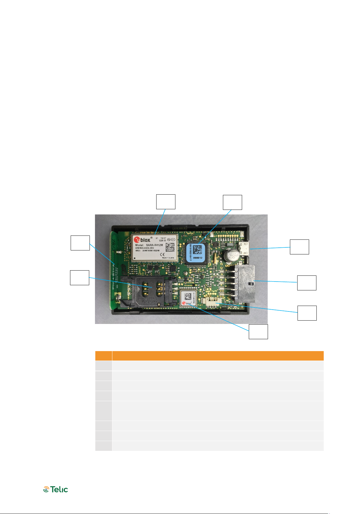
3.3 Functional Overview
The picture below gives an overview about the main components and its functions available on the
PCB after opening the upper lid.
Picture 1: Functional Overview
Function
1
Mobile Service module LTE Cat.M1 with 2G fallback
2
Microcontroller
3
Micro USB
4
Molex connector
5
Connector for the rechargeable battery; the battery is placed in the device
lid
6
GNSS module
7
SIM card holder
8
Mobile Antenna
Table 2: Device components
4
7
5
3
6
8
1
2

SBC AVL 4G User Manual - Telic AG
Pg 9
3.4 Wiring description
Signal
Cable Color
Connection
VCC /DIG IN 3
Red (pin 1)
Required
GND
Black (pin 6)
Required
IGNITION INPUT
Yellow (pin 5)
Recommended
DIG_IN 2 (ANA_IN1)
Violet (pin 4)
Optional
1-wire
Grey (pin 7)
Optional
DIG_OUT1
Orange (pin3)
Optional
DIG_OUT2
Brown (pin2)
Optional
RS232 LVTTL RX
White (pin 9)
Optional
RS232 LVTTL TX
Blue (pin 10)
Optional
Table 3: SBC AVL 4G Cable Color description
The following voltage ranges apply:
+7 V to +32 V for VCC/external power supply / Ignition Input / Dig IN
0 V for GND
Please observe also the following wiring diagrams:
Picture 4: Wiring 1-wire Sensors
Picture 2: SBC AVL 4G Cable Pin allocation
This side up
Picture 3: SBC AVL 4G Connector

SBC AVL 4G User Manual - Telic AG
Pg 10
Picture 5: Wiring Digital Outputs
For the digital outputs DigOut1 and DigOut2, the following applies:
Max Values: 300mA/+30V
Low-Side-Switch: if triggered, the pin goes to 0V/GND
Notes:
If a relay is connected to the digital output, it must have the same common ground as the device
The voltages on inputs and outputs must be identical
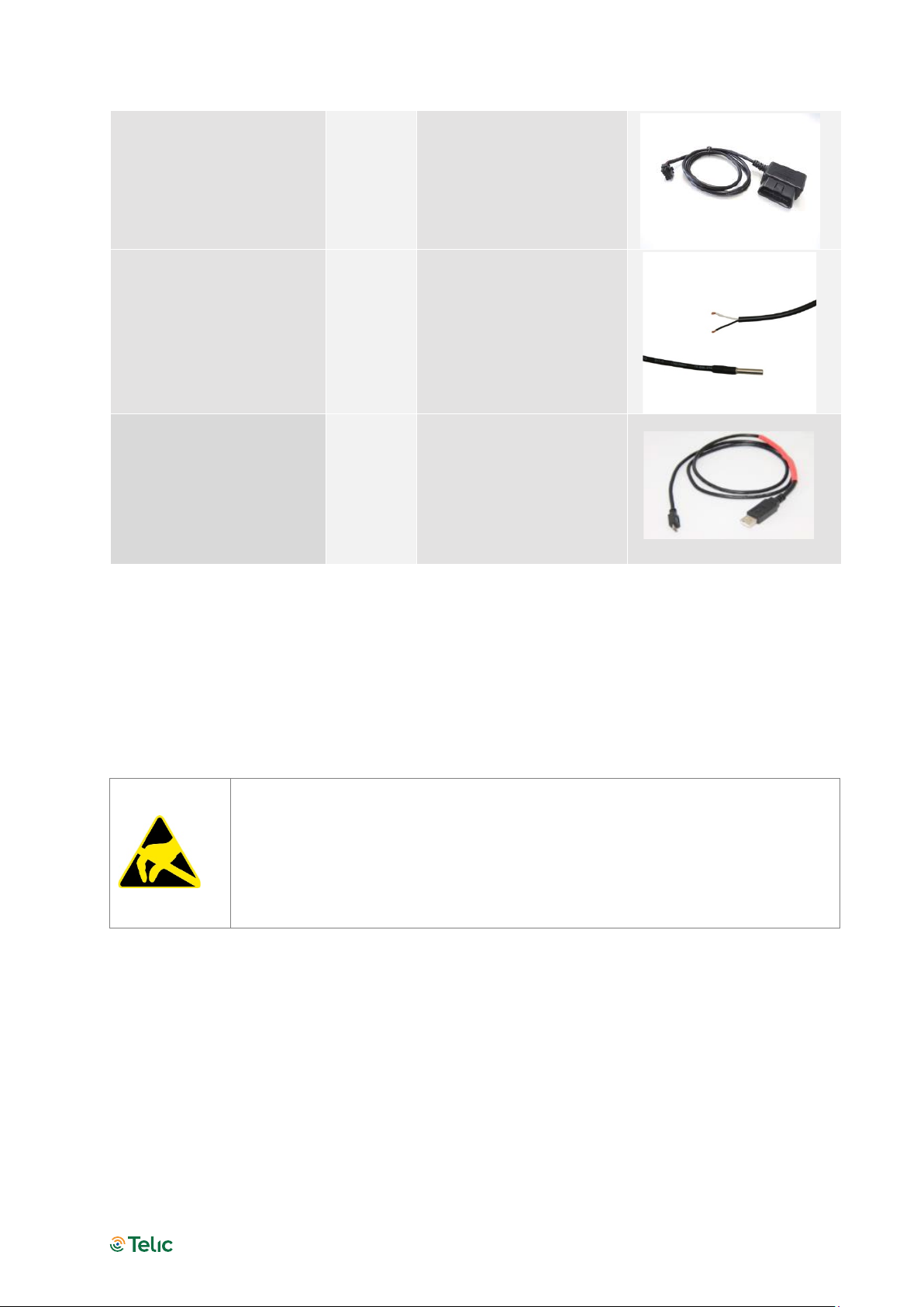
3.5 Delivery Content and Accessories
In addition to the SBC AVL 4G, the following accessories can be part of the shipment, if previously
ordered.
Accessory Name
Order
code
Functionality
Picture
Connection cable SBC
AVL 4G
16032
Automotive molex cable
for on vehicle installation
Cigarette lighter charger
SBC AVL 4G
17024
Charger cable for
connecting the device to
the Cigarette lighter
SBC AVL 4G User Manual - Telic AG
Pg 11
OBD II Power Supply
Cable
17023
2-pin OBD-II connector
cable for power supply
only;
Cable length: 1 m
1-wire Temperature
Sensor
90029
1-wire Temperature sensor;
Cable length: 7 m;
Temperature range: -55 °C
to +125 °C;
Accuracy: ± 0,5°C (in range
-10 °C to +85 °C)
Cable for RS232 Tracing
16207
User this cable to charge or
to configure the device via
the Telic Config-Tool
Table 4: List of accessories
4Operating Set up
The operation set-up of the tracking device can be realized in few quick steps.
Please take proper ESD protection measures (e.g. electrical connection of the
body to ground) to make sure you don’t destroy internal electronics! Repair of
ESD damages caused by user’s negligence will not be covered by Telic’s
warranty. Electrostatic discharge (ESD) is the sudden and momentary electric
current that flows between two objects at different electrical potentials normally
caused by static electricity.
4.1 Operating the device
Please open the SBC AVL 4G housing by pushing the button shown here:

SBC AVL 4G User Manual - Telic AG
Pg 12
Picture 6: The button to open the SBC AVL 4G Housing
While keeping the button pushed, remove the top cover with the other hand as shown. The SIM card
holder can be found under the top cover.
Picture 7: How to open the SBC AVL 4G Housing
4.2 Insert the SIM Card
A working SIM card from a suitable network provider must be properly inserted so that the device
operates correctly.
If the SIM card is not PIN free, it has to be ensured that the PIN is set to “0000”.
To speed up the log-in process into the mobile network, the SIM card should
contain no or only a few phone book entries.
The messages of the SBC AVL 4G are transmitted via the mobile network.
Therefore you need a standard 3 Volts or 1.8 Volts SIM card.
SBC AVL 4G User Manual - Telic AG
Pg 13
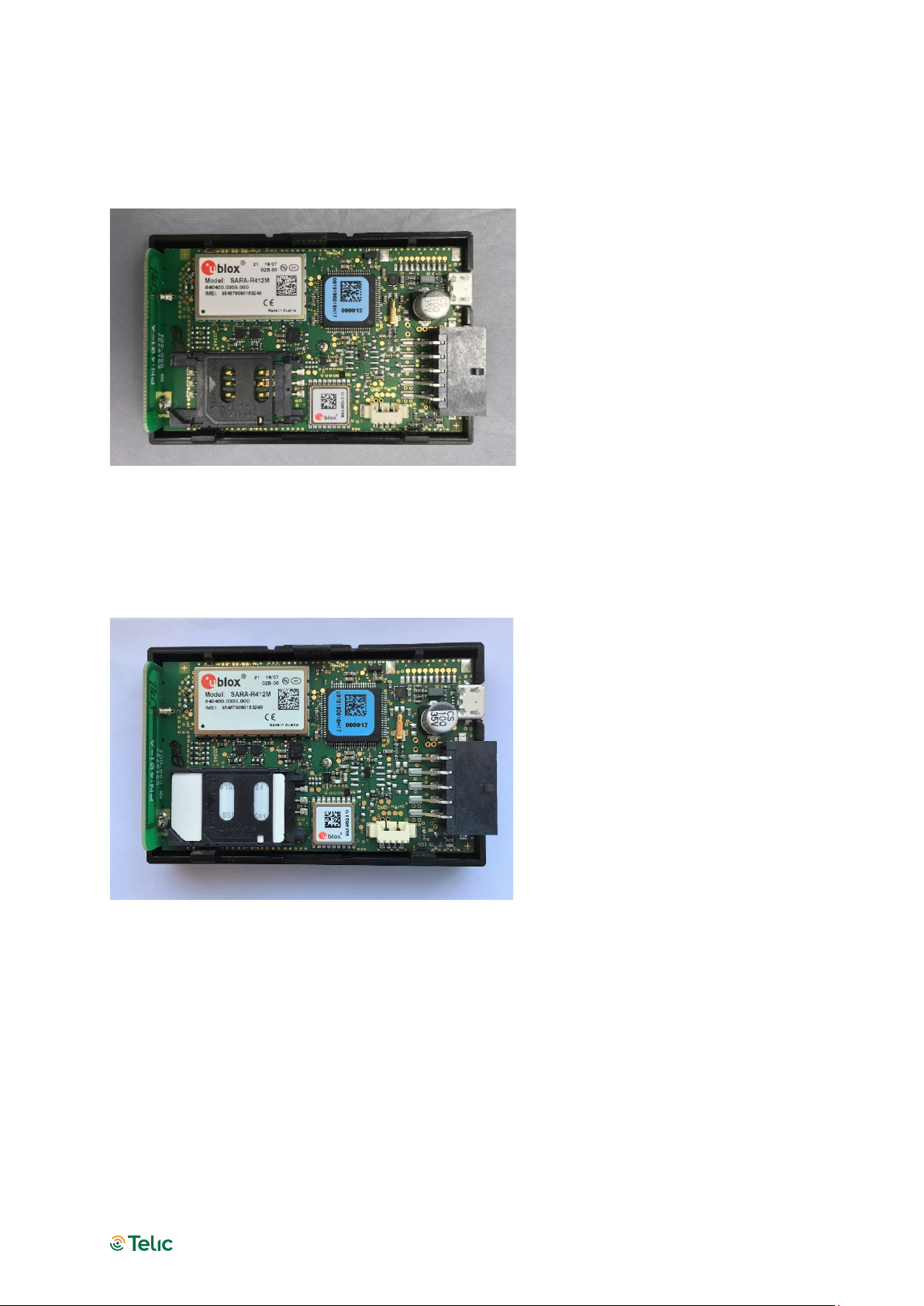
The insertion of the SIM card into the SBC AVL 4G is easy:
Place the device in front of you as showed in the picture.
Slide the SIM card cover carefully to left.
Picture 8: How to insert the SIM Card
Carefully flip the card reader sideways then up. Now insert the SIM card into the SIM card holder so
that the cut corner matches with the corresponding marking on the SIM card holder. Do not touch
the contacts of the SIM card. If necessary to clean the contacts with a soft cloth.
Picture 9: Where to insert the SIM Card
When inserted correctly the gold contacts of the SIM card should be facing down.
Flip the SIM card holder back into its original position and slide the lock back on right till it is
locked
If you cannot close the SIM card holder, you may have inserted the SIM card in the wrong direction
With this step you have finished the SIM card installation.
Now you have to connect the rechargeable battery connector to the 4-pins connector on the PCB.

SBC AVL 4G User Manual - Telic AG
Pg 14
4.3 Close the cover
Please close the SBC AVL 4G housing by pushing the top cover against the down side until there is no
more space between the 2 surfaces.
Picture 10: How to close the SBC AVL 4G Housing

SBC AVL 4G User Manual - Telic AG
Pg 15
5Status indicators
Left indicator: Power supply status
Middle Indicator: Mobile status
Right Indicator: GNSS status
The left indicator consists of a red
one
When the LED is off, the device is
not powered even in sleep
mode.
Blinking once: Powered (7-32V)
and internal battery fully
charged.
Blinking twice: Low battery
voltage
On: Internal battery charging.
The orange LED reflects the
mobile status and also whether
the device is switching on.
When the LED is off, the mobile
module is not active.
Permanently on: mobile is
active, but no network available
/ not yet registered.
Blinking once: Device is logged
into the mobile network, no
connection to server.
Blinking twice: Device is logged
into the mobile network,
established TCP/ IP connection
to server.
A very short flash while the
device is in sleep mode means
that a movement has been
detected.
This LED blinks green and
indicates the status of the GNSS
receiver.
Off: GNSS is not switched on.
Blinking once: Position
acquisition.
Blinking twice: 2D-Fix (no valid
height).
Blinking three times: 3D-Fix
(GNSS data is complete).
After start up as well as after a
phase without GNSS reception
the device only accepts 3D
GNSS positions.
This ensures, that 2D positions
reports with serious deviations
from the real position are not
reported to the control center.
After a while, 2D position
reports are accepted because
the GPS receiver had enough
time to evaluate the signal
quality of all available satellites.
A very short flash every 2
seconds
indicates that the
device is in sleep mode.
Table 5: LEDs behaviour

SBC AVL 4G User Manual - Telic AG
Pg 16
6Connect to the vehicle
This paragraph describes the procedure to install the device on board of your vehicle and check if the
installation has been performed properly.
Please take proper ESD protection measures (e.g. electrical connection of the
body to ground) to make sure you don’t destroy internal electronics! Repair of
ESD damages caused by users negligence will not be covered by Telic’s
warranty. Electrostatic discharge (ESD) is the sudden and momentary electric
current that flows between two objects at different electrical potentials normally
caused by static electricity.
6.1 Placing the device into the vehicle
In order to protect your vehicle from theft and vandalism the device should be installed in a location
where it and its power supply are well-hidden. Using the cable-cases on box surfaces, please install the
device in a suitable, dry location, not in contact to radio and audio frequency interference or hot parts
of the vehicle like near the engine. When installing the device, please consider that antennas are
integrated, this means it must be installed in a place with a minimum distance of 7 cm to metallic
components of the vehicle in each direction. In order to optimize the quality of the signal received, the
surface of the internal GNSS antenna must be installed looking at the sky (see the label indication on
the device box, this side up).
6.2 Wiring connection
Please connect the Telic SBC AVL 4G with the vehicle according to the following instructions using the
connection cable. Please do not connect the connector to the Telic SBC AVL 4G before all wires you
intend to use are connected to the vehicle. The power supply has to be available while the ignition is
off.
The black wire (pin 6 on Molex connector) must be connected to the GROUND (pin 31 of the vehicle)
and the red wire (pin 1 on Molex connector) must be connected to VCC (pin 30 of the vehicle).
The yellow wire (pin 5 on Molex connector) must be connected to ignition (pin 15 of the vehicle).
All other wires have to be connected to the related interface, otherwise please ensure that they cannot
cause short circuits.
The advantage of constant power supply is that the device is able to connect faster to the Mobile
network and it can find faster a new GNSS position after ignition was switched from “OFF” to “ON”.
This means that for example working time calculations will be more precise. With ignition off, the
power consumption of the Telic SBC AVL 4G is low enough that it does not interfere with proper
functionality of the vehicle battery.

SBC AVL 4G User Manual - Telic AG
Pg 17
If the Telic SBC AVL 4G is configured to use a motion dependent power mode, the device can detect
and report that it is moving (e.g. if it is stolen or being transported via a second vehicle) even while
ignition is off.
7Configuring a device
7.1 Basic event types
The SBC AVL 4G’s primarily task is to transmit GNSS position data including additional status
information via a TCP/IP connection to the telematic server. If a message can’t be transmitted, it will be
stored in the device to be transmitted later. There is a wide range of events that generate a position
message (they are all detailed in our SW specification).
The basic events are listed below:
Time event: the message is generated at the end of a time period of x seconds (x being
configurable);
Distance event: the message is generated once a distance of x meters (straight line distance to the
previous event) in any direction (x being configurable) has been travelled;
Angular course change event: the message is generated once there is a direction change of a
configurable minimum angle in x degrees (x being configured) at a configurable minimum speed of
y km/h (y being configured);
Periodic Wakeup / Routine Message: even when the unit is in stand-by mode, the message is
generated either every x hours (x being configurable) or at a fixed time (configurable) during the
day.
7.2 Power modes
The SBC AVL 4G’s can work with several power modes based upon the customer’s needs.
This allows to save the power consumption as much as possible and to extend the battery runtime.
The available power modes are listed below.
Full power mode
Microcontroller, mobile service and GNSS modules are always on.
Input sleep Mode
Microcontroller, mobile service and GNSS modules are turned off two minutes after the selected
digital input (e.g. Ignition) is set to low (both time and digital input can be changed in “Expert
Settings”).
Timer Sleep Mode
The device enters the sleep mode between the timer events (events generated every x minutes,
being x configurable). During sleep mode mobile and GNSS are turned off and microcontroller is in

SBC AVL 4G User Manual - Telic AG
Pg 18
low power mode. An input can be configured to wake up and stay awake until the input goes to
low again.
Motion Sleep Mode
If the motion sensor detects stationary, the device will switch off GNSS and mobile service modules,
and µC is switched to low power mode. Changes from "stationary" to "moving" will always wakeup
the system. Then it will stay awake as long as the sensor detects movement. GNSS and mobile
modules are turned on. If the device detects "stationary" for the stationary detection time period,
the device goes into the sleep mode after 60 seconds.
An input can be configured to wake up and stay awake until the input goes to low again.
Endurance Mode
Basically the Endurance Mode is similar to the Timer Sleep mode, combined with the Motion Sleep
Mode. As long as the device is moving, it behaves like in Timer Sleep mode. As soon as it falls to
stationary it wakes up, sends the stationary event (if configured) and falls back to sleep until the
next movement without generating cyclic messages. This sleep in stationary state can be
interrupted by routine or fixed reporting time events.
7.3 Basic configuration
The device can be configured via either serial interface or SMS.
In the first case you will need a simple cable (micro USB – USB connectors) and a serial terminal
program (e.g. Realterm).
In the second case, you will need in the device a SIM supporting SMS (M2M SIMs typically don’t
support them).
Before you insert the SIM card and activate the device, make sure the PIN is disabled or set to 0000.
Otherwise it can happen that the PIN is entered incorrectly three times, and the SIM falls into the PUK
lock.
This would be deactivated again by a mobile phone.
When sending SMS to a device through a mobile phone, the phone number of the latter must be
visible (not hidden), otherwise the device won’t send its reply to the sender.
Afterwards, you can check the flashing behaviour, Mobile LED should flash once, when the device is
logged into the mobile network, and twice when an IP connection to the server is established.
More detailed information can be found in the 5th chapter of this manual.
A lot of parameters can be configured in order to implement the proper use case.
Besides, the unit has to be configured in order to forward messages (events) to the proper server; in
the following paragraphs some scenarios will be illustrated as examples (all the details can be found in
the SW specifications, basic and expert type).
Tracking – typical configuration profiles
Pedestrian & Vehicle Live (1min interval)
Position messages are generated every 60 seconds when in motion, regardless of speed or changes of
driving direction.

SBC AVL 4G User Manual - Telic AG
Pg 19
This means that a position message is generated and transmitted every 2 km on a freeway or highway
(driving with about 120km/h).
As soon as motion is ended (detected by built-in sensor), the device will go to sleep mode. When
going back to motion (detected by the sensor), the device will automatically resume tracking.
A routine event (“I am alive”) will be sent once a day.
Then the power mode will be motion-sleep mode (5), and time interval 60 sec.
The following extra messages are generated and sent to the server (value=2in the 32 bytes sequence
detailed below):
Power Supply connected / disconnected
Ignition signal on / off
Digital Input 2 signal on / off
Digital Input 4 signal on / off
Device stopped moving (30 seconds without any sensor motion detection)
Device started moving (according motion sensitivity level 3)
Periodic Wakeup / Routine message (every 24 hours)
Configuration SMS :
0011{6digitsIMEI},,,,60,0,200000700000,50000009,00000000022222220000000022000000,,,,,,0,0,0,0,24,,,,
3,30,,,,30,6
Configuration command through serial line:
CONFIG=,,,,60,0,200000700000,50000009,00000000022222220000000022000000,,,,,,0,0,0,0,24,,,,3,30,,,,3
0,6
Remark: the “0011{6digitsIMEI}” of the SMS becomes “CONFIG=” in the serial command; the rest remains
unchanged.
Vehicle - Medium Resolution - Off by Motion
Position messages are generated either after 5 km distance or as soon as the driving direction has
been changed more than 45 degrees provided that the vehicle is exceeding 20Km/h.
Driving long distances will be covered by one position message every 5 km, driving short distances is
managed by generating position messages whenever the driving direction is significantly changed.
As soon as the vehicle has stopped (detected by sensor) the device will go to sleep mode. When
vehicle goes back to move, the device will automatically resume tracking.
Power mode: motion-sleep mode (5)
Distance interval: 5,000 mt
Course change: 45 degrees
Minimum Speed: 20 Km/h
In addition the following extra messages are generated and sent to the server:
Power On
Ignition signal on / off
Digital Input 2 signal on / off
Device stopped moving (1 minute without any sensor motion detection)
Device started moving (according motion sensitivity level 3)
Configuration SMS:
0011{6digitsIMEI),,,,0,5000,020000700000,50000009,20000200002222000000000022000000,,,,,,0,0,0,0,2
4,,,,3,60,,,,45,20
Vehicle - Low Resolution Track (10min interval)
Table of contents
Other Telic GPS manuals


