sotecc canopy flash Manual
Manual
Installation instructions
canopy flash
connectBOX & canopy-power interface
Version
1.3
Editor
SOTECC GmbH, Armbruststr. 75, 73230 Kirchheim unter Teck
Contact

© 2021 SOTECC GmbH. All rights reserved Rev. 1.3
Handbook/Installation instructions
Canopy flash
2
Table of content
Table of content ..................................................................................................................................... 2
1 Important information .................................................................................................................... 4
2 Emergency operation ...................................................................................................................... 4
3 Operation without connectBOX ...................................................................................................... 5
4 Operation with connectBOX............................................................................................................ 5
4.1 Automatic mode .................................................................................................................................... 5
4.1.1 Alarm mode ..................................................................................................................... 5
5 Serial number .................................................................................................................................. 6
6 Technical data.................................................................................................................................. 6
6.1 Canopy flash .......................................................................................................................................... 6
6.2 connectBOX ........................................................................................................................................... 6
6.3 Beam angle ............................................................................................................................................ 7
7 Components overview..................................................................................................................... 7
7.1 Canopy flash .......................................................................................................................................... 7
7.1.1 LED function indicator ..................................................................................................... 8
7.2 connectBOX ........................................................................................................................................... 8
7.3 Quick separation point .......................................................................................................................... 9
7.4 Canopy-power interface (optional) ..................................................................................................... 10
7.5 Extension Board (optional).................................................................................................................. 10
8 Installation instructions................................................................................................................. 11
8.1 General ................................................................................................................................................ 11
8.2 List of needed tools and materials ...................................................................................................... 11
8.3 Installation of the canopy flash with template.................................................................................... 12
8.4 Installation of the canopy-power interface ......................................................................................... 13
8.5 Canopy-power interface counterpart attachment with template ...................................................... 14
8.6 Installation of the counterpart to the instrument panel cover ........................................................... 14
8.7 connectBOX ......................................................................................................................................... 15
8.8 Video.................................................................................................................................................... 15
8.9 Wiring .................................................................................................................................................. 16
8.10 Option Extension Board....................................................................................................................... 17
9 SOTECC-Configurator..................................................................................................................... 18
9.1 Establish connection............................................................................................................................ 18
9.2 Programming ....................................................................................................................................... 19
9.2.1 Programmable Parameters ........................................................................................... 19
9.2.2 Test mode...................................................................................................................... 19
9.2.3 Finish programming....................................................................................................... 19

© 2021 SOTECC GmbH. All rights reserved Rev. 1.3
Handbook/Installation instructions
Canopy flash
3
10 Safety notes............................................................................................................................... 20
11 Attachments .............................................................................................................................. 21
11.1 Electrical schematic canopy flash with connectBOX ........................................................................... 21
11.2 Electrical schematic canopy flash ........................................................................................................ 22
12 Spare parts................................................................................................................................. 23
13 contact....................................................................................................................................... 23

© 2021 SOTECC GmbH. All rights reserved Rev. 1.3
Handbook/Installation instructions
Canopy flash
4
1Important information
Installation and usage of the canopy flash is at your own risk and responsibility. It requires approval by
an aircraft inspector authorized for such work and a complete documentation and is only allowed to
be operated on board of gliders under VFR-daylight flight rules. Improper installation may lead to
failure of the aircraft avionic system. The canopy flash is a system to enhance flight safety. The
improved visibility results in a faster detection of aircraft, however the system solely assists airspace
observation by the PILOT IN COMMAND and must not replace it at any time. SOTECC will not cover
failures due to unauthorized installation, alterations, repairs, abuse, misuse or accidents.
SOTECC GmbH reserves the right to amend its products regarding technical data and functions without
previous notice. SOTECC accepts no liability for mistakes in writing, misprints or miscalculations or any
other errors and has the right to withdraw at any time.
Caution, high intensity optical radiation!
Handling on ground: do not look directly into the light!
Avoid direct contact with water!
2Emergency operation
In the event of a malfunction or failure, the system must be switched off immediately and must stay
off for the remaining flight time. Never switch on the system again inflight, after or while persisting
errors.

© 2021 SOTECC GmbH. All rights reserved Rev. 1.3
Handbook/Installation instructions
Canopy flash
5
3Operation without connectBOX
After switching on (by switch/fuse) the canopy flash starts flashing with a frequency of 0,6Hz, e.g. a
flash every 1,5sec. This frequency is a compromise between visibility and power consumption and
cannot be modified or adapted via the SOTECC-configurator. As there is no connection to FLARM®,
evaluation of collision data or similar is not possible and it results in a steady flash frequency as long
as the system is switched on.
4Operation with connectBOX
4.1 Automatic mode
Switching on the power supply (and if exist, closing the canopy-power interface), activates systems
function test. This test includes flashing for 5sec with the „normal flight flash frequency“ to detect
internal errors and to make sure that the system works properly.
Connection between canopy flash and FLARM® is made possible by the connectBOX. As soon as the
FLARM® recognizes a takeoff (depending on a preset velocity), it thereupon sends this information via
the connectBOX to the canopy flash. The canopy flash then starts flashing with a battery saving
frequency of 0,6Hz, e.g. a flash every 1,5sec or set individually via the SOTECC-Configurator. After
landing and coming to a complete stop, the canopy flash stops flashing automatically. Information
regarding adjustment of the „normal flight flash frequency“ (battery saving frequency), programming
and updating of the connectBOX under the item 10 „SOTECC-Configurator“.
4.1.1 Alarm mode
A collision threat detected by FLARM® changes the flash frequency and its flash pattern instantly. The
„flashes“ are getting longer with a higher flash frequency and thus even more striking. Triggering alarm
mode depends on several parameters:
-Approach angle of conflicting traffic within +- 45 degrees and only oncoming traffic
-Collision warning by FLARM®. The alarm-threshold can be changed with help of the SOTECC-
configurator, default setting is „important alarm“. Selectable modes are „low alarm“
(moderate danger with approach time between 19 – 25 s), „important alarm“ (medium danger
with approach time between 14 – 18 s) and „urgent alarm“ (immediate danger with approach
time between 6 - 8 s). These data is analog to FLARM®„warning level“. Further information in
the handbook of FLARM® or [email protected].
After being clear of conflict and passing the oncoming traffic safely, the canopy flash automatically
switches back to the „normal flight flash frequency“.

© 2021 SOTECC GmbH. All rights reserved Rev. 1.3
Handbook/Installation instructions
Canopy flash
6
5Serial number
All components are labeled with serial numbers for clear identification, composed of letters and
numbers like:
ACL 3820 501 0001 / FW 1.4 S
(a) (b) (c) (d) (e)
(a) Component (ACL=canopy flash, FC=connectBOX)
(b) Date of production (example: CW38/2020)
(c) Version (example: 501)
(d) Consecutive number example: 0001)
(e) Firmware (example: FW 1.4)
6Technical data
6.1 Canopy flash
Luminous flux
~ 2200 lm (white LEDs, red similar)
Beam angle
~ 18° concentrated light beam, ~ 60-70° visible
Beam current
25000 mW (white LEDs, red similar)
Power consumption
Ø 100mA at 13V and „normal flight flash
frequency“ without warnings
Operating voltage
9-15 V DC
Weight
90g
Operating temperature
−30 °C to + 70 °C
Overheat protection
70 °C
Material
3D-printed, resistant PA12 plastic
6.2 connectBOX
Power consumption
Ø50mA at 13V
Operating voltage
9-15 V DC
Weight
120g
Operating temperature
−30 °C to + 85 °C
Dimensions
50mm x 50mm x25mm
Material
Aluminium housing

© 2021 SOTECC GmbH. All rights reserved Rev. 1.3
Handbook/Installation instructions
Canopy flash
7
6.3 Beam angle
area 1
area 2 area 2
Area 1: ~ 18° concentrated light beam, which can be seen about 3500m, depending on the prevailing
conditions.
Area 2: Peripheral area, ~ 60 - 70 degrees wide, but slightly weaker. Visibility can differ significantly,
depending on outside conditions.
7Components overview
7.1 Canopy flash
The housing of the canopy flash is made of resistant PA12 plastic. Cooling fins on the bottom side
ensures heat dissipation and minimizes overheat risk, especially in strong sunlight. Five high quality

© 2021 SOTECC GmbH. All rights reserved Rev. 1.3
Handbook/Installation instructions
Canopy flash
8
CREE® LEDs (either white or red) in combination with LED lenses, generating a bundled and strong light
beam. An integrated LED on the backside of the canopy flash housing informs the pilot about the
proper functioning of the system (see item 3). The heart of each canopy flash is the energy saving LED-
control unit with an integrated temperature and error control unit, to prevent system overheat or
internal damage. If a temperature of about 70°C is exceeded, the canopy flash automatically switches
off, however this temperature cannot be reached in normal operation, only if the system has a
malfunction or in extreme sunlight on ground.
7.1.1 LED function indicator
An integrated LED on the backside of the canopy flash housing informs the pilot about the proper
functioning of the system. Possible indications can be:
Steady green, active system inflight mode, flashing with energy saving frequency.
Flashing green/red, collision threat recognized, flashing with striking frequency (alarm-mode).
Steady red, automatically switched off to prevent system overheat. Wait until green light
appears.
7.2 connectBOX
The connectBOX connects the canopy flash with FLARM® and makes an automatic operation possible.
This results in 3 different modes:
•Mode 1: Canopy flash off on ground without movement. (waiting for take-off)

© 2021 SOTECC GmbH. All rights reserved Rev. 1.3
Handbook/Installation instructions
Canopy flash
9
•Mode 2: Once gaining speed and taking-off, the canopy flash automatically starts flashing
with the „normal flight flash frequency“
•Mode 3: If an imminent collision is detected by FLARM®, the flash frequency and flash pattern
changes instantly.
7.3 Quick separation point
A mini XLR plug without locking guarantees a safe canopy jettison and connects canopy flash and
connectBOX. (For gliders like LS8, ASG29, V3M)

© 2021 SOTECC GmbH. All rights reserved Rev. 1.3
Handbook/Installation instructions
Canopy flash
10
7.4 Canopy-power interface (optional)
The canopy-power interface is required for canopies opening to the right (like the most Schempp-Hirth
canopies) and guarantees a safe canopy jettison and a permanent power supply.
7.5 Extension Board (optional)

© 2021 SOTECC GmbH. All rights reserved Rev. 1.3
Handbook/Installation instructions
Canopy flash
11
8Installation instructions
8.1 General
The canopy flash falls within the category standard parts, according to EASA AMC 21.A.303(c), and so
installation in gliders is only allowed under certain conditions. Der installation must comply with the
EASA Standard Change CS-SC036a „INSTALLATION OF VISUAL AWARENESS LIGHTS“. It is necessary to
ensure the following items:
-The Pilot shall not be blinded by the canopy flash system under no circumstances. In certain
weather/sunlight conditions and if installed improperly, the pilot might perceive some light on
the canopy frame. However, the light intensity is weaker than the LED function indicator on
the backside of the canopy flash and is not blinding or distracting the pilot.
-Installation of a switch on the instrument panel, labeled with „on (auto)/off“. The pilot shall
be able to cut the power supply by this switch in the event of a malfunction at any time. It is
alternatively allowed to use a switch rated circuit-breaker.
-the general flight characteristics are maintained.
-The canopy jettison must not be affected in a negative way. Gliders equipped with a canopy
opening to the right (like to most Schempp-Hirth canopies) are obliged to use the SOTECC-
canopy-power interface.
-Other aircraft avionics, especially the radio system, are not disturbed.
-Compliance to all center of gravity and mass limitations.
-Approval by an aircraft inspector authorized for such work and a complete documentation.
-In order to guarantee a safe operation, all these items mentioned above need to be checked
and have to be complied with, prior any flight.
The current version can be found on the EASA-Homepage.
8.2 List of needed tools and materials
-Torx-screwdriver TX8
-3mm allen key
-Cutter
-Side-cutter
-Velcro tape
-Cable ties
-Thin thread
-Foam cleaner, or the preferred tool to clean the canopy
-2,5 mm drill
Before fitting, check the foam tapes on the bar of the canopy flasher for correct fit
(these can slip or come off during transport). Check the red 3M adhesive strips for
pressure points.

© 2021 SOTECC GmbH. All rights reserved Rev. 1.3
Handbook/Installation instructions
Canopy flash
12
8.3 Installation of the canopy flash with template
Define the middle of the canopy with a thin string or
tape, then affix the template from outside. (Be careful:
the small string may be positioned eccentrically!) Prior
installing the canopy flash, clean the canopy with
appropriate cleaning agent.
Then carefully remove the protective foil on the 3M
adhesive strip with a cutter or something similar.
Be careful: Don´t detach the 3M adhesive strip from the canopy once it had contact
with it. (It is simply not possible without destroying the 3M tape.)
Subsequently align the canopy flash in accordance with
the template, BUT press on the frontpart first, then
swing the rear part up and press it on, this avoids air
bubbles.

© 2021 SOTECC GmbH. All rights reserved Rev. 1.3
Handbook/Installation instructions
Canopy flash
13
The front template spacers shall be positioned approx.
1mm behind the canopy paint edge. (direction to the
tail). Various installation examples can be found here
(https://einbau.sotecc.de). The password can be found
in the enclosed cover letter.
8.4 Installation of the canopy-power interface
Only for aircraft with side opening canopies (e.g. Schempp-Hirth). For these aircraft the
canopy contact is a necessary component for operation! Aircraft with forward opening
canopies without canopy contact go to 8.9 "Wiring".
Lay the cable from the canopy flash into the canopy frame
and if necessary, fix it. Make sure to place the power
interface as close as possible to the frame. However, the
3M tape must rest flat on the canopy, without any tilt, to
guarantee a solid bond. Clean the canopy prior attachment
of the canopy-power interface and do not detach it once it
already had contact with the canopy. Loosen the two big
screws just a little bit, so that the canopy-power interface
can be moved smoothly and without big resistance on the
mounting bracket. Now put the plastic template (in the
bag) on the Allen screws of the canopy-power interface
and remove the protection foil of the double-sided tape.
Ventus 3S: Installation without mounting bracket.

© 2021 SOTECC GmbH. All rights reserved Rev. 1.3
Handbook/Installation instructions
Canopy flash
14
8.5 Canopy-power interface counterpart attachment with template
Tip: Sometimes this step is easier when sitting inside the
cockpit.
Now close & lock the canopy and place the contact with the
doubled-sided tape flat on to instrument panel cover and
press it on. Then tighten the two screws to avoid movement
of the canopy-power interface on the bracket. Open the
canopy carefully and make sure, that the template does not
get out of place.
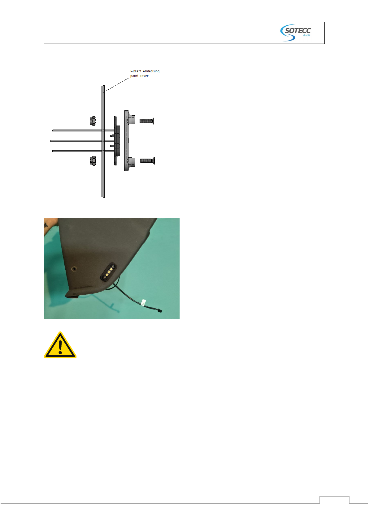
8.6 Installation of the counterpart to the instrument panel cover
Remove the panel cover for this step.
Fix the template by drilling two 2,5mm holes and screw
it tight. Now mill out the inner part of the template,
either with a milling tool or with two drills. (7mm left
and right and 10mm in the middle)
If necessary, finish it with a round file, then remove the
template (keep the screws).
Put the counterpart cable through the panel. Use the
plastic component (looks quite similar to the template)
and tighten the screws (already used for the template).
Caution: Red/plus must be to the front inflight direction. Or take heed of the white dot,
they have to lie on top of each other.
© 2021 SOTECC GmbH. All rights reserved Rev. 1.3
Handbook/Installation instructions
Canopy flash
15
Fix the cable with the cable holder, install the
suppressor, mount the panel cover and check if
canopy-power interface and the counterpart align
to each other by closing the canopy carefully.
If the canopy-power interface and the counterpart
are not aligned to each other, it is possible to make
smaller adjustments on the canopy-power
interface. Loosen the two screws and relocate the
contact on the bracket. Larger deviations can only
be solved by relocating the whole canopy-power
interface on the canopy. (If this is unavoidable,
When closing the canopy, the canopy-power interface and the counterpart must not
jam each other.
8.7 connectBOX
Install the connectBOX if possible close to the quick separation point or to the counterpart to have
access to the ports and fix it either with screws or with Velcro.
8.8 Video
A detailed video about the installation can be found here:
https://www.youtube.com/watch?v=yTdoDFpJMLg&feature=emb_title

© 2021 SOTECC GmbH. All rights reserved Rev. 1.3
Handbook/Installation instructions
Canopy flash
16
8.9 Wiring
Plug the 4-pin connector cable of the counterpart (in the panel
cover, see step 5, lower picture) into the ACL-port of the
connectBOX.
Similar way for canopy flash systems with quick separation
point (like V3M, LS8)
Connect the connectBOX to the on-board power supply with
the 2-pin cable and install a 3-5 A fuse. If necessary shorten the
power cable and then plug it into the power port of the
connectBOX. To disconnect the connectBOX manually from
the on-board power, place the switch between the power
cable.
Cable to the
canopy-flasher at the top (ACL), connection to the on-board power supply at
the bottom (Power). (The connectBOX is installed tilted 90 degrees to the right in the photo).
© 2021 SOTECC GmbH. All rights reserved Rev. 1.3
Handbook/Installation instructions
Canopy flash
17
The quick separation point must not be glued or secured, otherwise the ease of
separation would be lost!
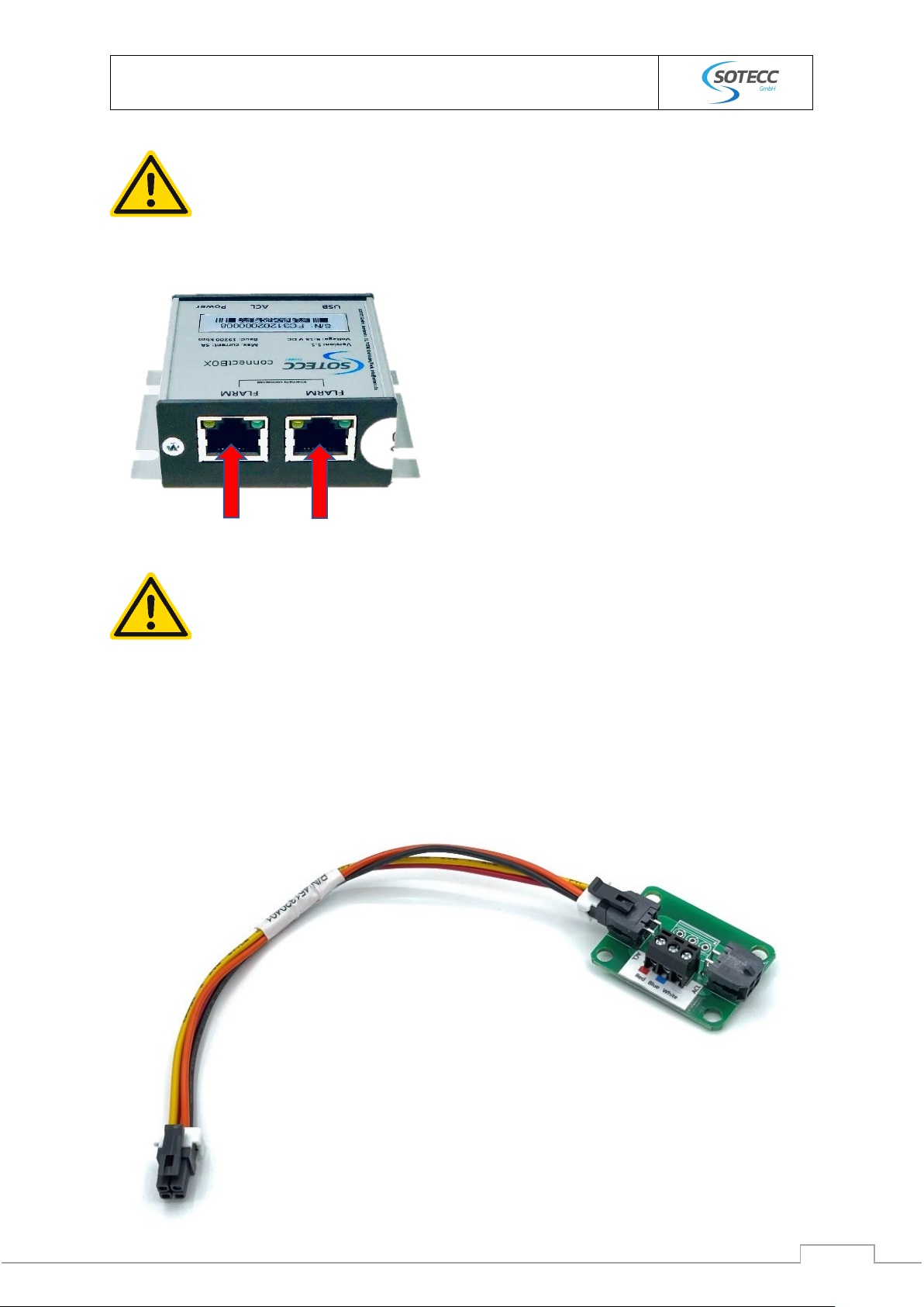
Finally connect FLARM® with RJ45 or RJ12 cable to the
connectBOX.
Both RJ Ports of the connectBOX are internally
connected and can be used as a splitter (loop-
through). It is possible to use 8-pin (RJ45), or 6-pin
(RJ12) plugs.
TRX-1090 “Bluebox“ can not be connected to the connectBOX. If necessary, connect
FLARM® upstream with the connectBOX and then “Bluebox” downstream.
8.10 Option Extension Board
If the connectBOX is difficult to access or if it is installed in combination with a SOTECC-strobe, the
extension board is used, to enable easy plugging in and unplugging when removing the instrument
panel cover.
© 2021 SOTECC GmbH. All rights reserved Rev. 1.3
Handbook/Installation instructions
Canopy flash
18
9SOTECC-Configurator
With the supplied SOTECC configurator, it is possible to configure the canopy flash via the connectBOX
individually. You can find the program attached on the supplied USB-stick. The following values can be
changed:
-Flash frequency
-Alarm-level threshold
-LED
-Baud rate
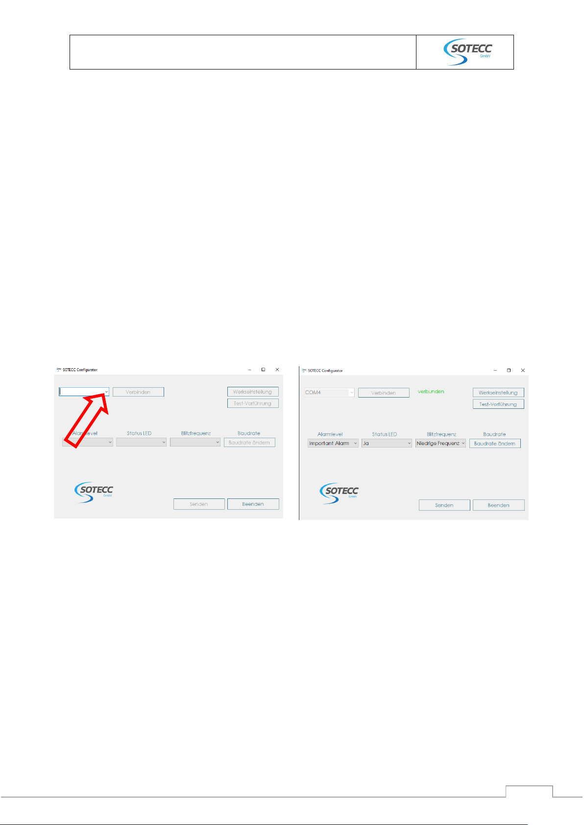
9.1 Establish connection
To configure the canopy flash via the connectBOX, connect the micro USB-cable to its designated port
on the box, ensure power e.g. aircrafts on-board power supply, start the SOTECC configurator, select
the COM-port, press „connect“ and wait for connection (2-5 sec). If there is no COM-port indicated on
the upper left side of the program, you may try to
-Connect onboard power supply, switch batteries on
-Load USB-drivers, which should be done automatically, if there is a connection to the internet
(duration is about one minute)
After successful connection, you will see the current (default) parameters and „connected“ in green
next to the „connect“ button. If there is no response after 5 seconds, you may try to
-Select the correct COM-port
-Retry to load the USB-drivers

© 2021 SOTECC GmbH. All rights reserved Rev. 1.3
Handbook/Installation instructions
Canopy flash
19
9.2 Programming
9.2.1 Programmable Parameters
9.2.1.1 Alarm level
Alarm level means the threshold at which an alarm is triggered. For more information, see chapter 3.
You can select one of the following:
-„low alarm“
-„important alarm“
-„urgent alarm“
Default setting is „important alarm“.
9.2.1.2 Function LED
It is possible to switch off the pilot-facing function LED. Default setting is “ON”.
9.2.1.3 Flash frequency
Frequency means the normal frequency without any alarm from the FLARM. There is:
-Low frequency (one flash every 2,2s)
-Normal frequency (one flash every 1,5s)
-High frequency (approximately 1Hz)
9.2.1.4 Baud rate
The Baud rate is set to 19,2 kbps by default. There might be (especially multi-function-)
systems, that require a higher baud rate. You can change the value by pressing “Baud
rate”. Normally it is not necessary to change it. Please check the documentation of your
connected system.
You can decide between the following options:
-9600 bps
-19200 bps
-38400 bps
-57600 bps
-115200 bps
9.2.2 Test mode
By pressing “test mode“, the canopy flash begins a 15 seconds test-mode and shows the programmed
flash frequency allowing the pilot to check the functionality of the canopy flash system. Please do not
interfere during this mode. (No programming during test mode).
Handling on ground: do not look directly into the light!
9.2.3 Finish programming
To finish the programming process, press “send”. The program confirms a successful programming by
showing the following message “programming successful”. After receiving this message, please restart
the connectBOX (turn off the onboard power), wait for at least 3 seconds and restart the system.

© 2021 SOTECC GmbH. All rights reserved Rev. 1.3
Handbook/Installation instructions
Canopy flash
20
10 Safety notes
The canopy flash is a system to improve visibility by other air traffic participants in the airspace. It
serves only as a support and under no circumstances replaces an active airspace observation by the
pilot in command. The installation of the system should not lead to any changes in the responsibilities
of the pilot in command. The rules for aircraft of the respective country in whose airspace the aircraft
is located apply. For a safe operation with connectBOX, GPS (Global Positioning System) with sufficient
signal and a functional FLARM® device with current firmware is required.
The system is only to be used for the intended purpose according to this manual.
We have provided all information to the best of our knowledge and belief. They correspond to the
current state of the art. The information does not constitute a warranty in the legal sense. SOTECC is
not responsible for damages resulting from negligence or improper use.
Table of contents


