Soto Muka OD-1NP User manual

Patent Pending
SOTO USA Inc.
110 Rustic Place, Eugene, Oregon 97401 USA
Phone: 503-314-5119
[email protected] www.sotooutdoors.com
Shinfuji Burner CO.,LTD.
1-1-3 Miyukihama, Mito-cho, Toyokawa-city,
Aichi-pref, 441-0314 Japan
Phone:+81 533 75 5000 FAX:+81 533 75 5033
EN
O D - 1 N P
M U K A
STOVE
STOVE
Instruction Manual
Be sure to read this manual carefully before using the Muka. Keep this manual for future reference and
review its contents regularly to keep aware of procedures and warnings. Failure to follow the warnings
described in this manual may result in fire, property damage, injury, or death. Please contact your
retailer or SOTO if you have any maintenance or repair related questions.
Cautions and Warnings
Applicable Fuel
●Never use the stove near any flammable materials.
Keep all such materials at least 1m (3 ft.) away from
sides of the stove and at least 1.5m (5 ft.)
away from top while stove is in use.
●Use only SOTO approved
windscreens with the the Muka.
The windscreen is intended only
to be used with the stove. Never
cover the fuel with a windscreen
while the stove is in use. Avoid
exposing the fuel to heat. The
bottle may explode if exposed to
heat.
●This stove can produce carbon monoxide, which has
no odor. Using it in an enclosed space can be deadly.
Never use this stove in an enclosed space, including a
camper, tent, car, or home. Failure to follow this
instruction may cause injury or death.
White gasoline only.
●NEVER use any fuel or liquid other than those specifically indicated in this manual.
●NEVER cross-contaminate the stove/bottle unit with fuel/liquid that is not recommended. Be sure to use a
clean vessel to carry the designated fuel. Failure to follow this instruction may clog the generator unit.
●The fuel used is highly volatile fuel. Be careful when handling such fuel.
●Do not use old fuel. Old fuel may clog the generator unit.
Regarding the Control Dial (CD)
◆"UNLOCK" position or
“OPERATING” position:
The "OPERATING" position will
enable the dial to turn and
engage the CD with the 4
positions: STOP, START, RUN,
and AIR.
◆“LOCK” position:
The Control Dial will lock when it is pressed.
The “LOCK” position will prevent accidental
engagement of the operating mode. Always
press the CD to the “LOCK” position when
stowing the stove or when traveling.
◆Emergency Stop:
Place the CD in the “LOCK” position to extinguish the flame
when an emergency arises. The “LOCK” position will cut off the
fuel supply immediately but the residual fuel remaining inside the
hose may take time to burn off.
1m
(3 ft.)
1m
(3 ft.)
1.5m
(5 ft.)
①Unfold the three pot supports.
②Fill the fuel to the "DO NOT FILL ABOVE THIS LINE" mark.
③Insert pump and screw down.
Do not connect the hose at this point.
④Wipe off any spilled fuel with a clean cloth.
①Make sure that the Control Dial (CD) is in the locked position
(depressed position), and it is set at the “STOP” position.
②Begin pumping using full strokes. When a red mark on the Pressure
Indicator becomes visible, stop pumping.
The red line on the Pressure Indicator means that optimal pressure has
built up inside the bottle.
CAUTION: Excess pressure may cause a leaping red flame at start up. Do
not over-pressurize the bottle. Less pressure may cause a failure to ignite the
flame properly.
21cm
(8 inch)
4.5kg
(10 lbs.)
●Make sure no fuel is leaking
out before lighting the stove.
Stop operating the stove
immediately if a fuel leak is
found. Never light a stove that
is leaking fuel.
●Never move a hot stove or a stove that is in use. Wait
until the stove is completely cooled before touching.
●Never leave a burning or hot stove unattended.
●Keep children and/or pets away from stove and never
leave it unsupervised.
●Use the stove only as intended for
cooking food and boiling water. Do
not use pans with a diameter
exceeding 21cm (8 in.). The weight of
the pan plus food should not exceed
4.5kg (10 lbs.).
●Stop operating the stove if the ambient temperature falls
below -20°C (-4°F) because the O-ring will temporarily
harden and lose elasticity, causing the fuel to leak.
●Never use 2 stoves
side-by-side (i.e., a griddle),
as this may cause the stove
to deform or expode.
●ALWAYS store the fuel in a
cool area. Never expose fuel
to direct sunlight and never
leave inside tent or car.
Heated fuel may explode.
●Always keep the connection between hose and pump
clean. Failure to keep the connection clean may cause a
fuel leak.
●The generator unit on the Muka
Stove has been engineered
precisely to accomplish
instantaneous ignition, i.e.,
non-priming. Be sure to treat it
carefully. Dropping or throwing
may cause damage to the
generator unit which may require
a replacement. (Part#: OD-GRN).
●The Muka Stove’s flexible hose
provides smooth and easy
operation when setting up and
stowing. NEVER bend the hose
more than 90°. Failure to follow
this instruction may cause a fuel
leak. Stop using the stove when
any fuel leak is found.
●Use only the SOTO Wide Mouth Bottle. Be sure to
read instructions printed on the bottle before use.
●IMPORTANT!!! Always check the lip on top of the
bottle and the O-ring P-34 on
the Smart Pump for wear-and-
tear, including dust, deforma-
tion, and cuts. This could cause
the fuel to leak, resulting in fire,
bodily injury, and even death. If
dirty, clean the flat lip and the
O-ring. Replace the O-ring if
wear-and-tear has occurred.
Replace the bottle if the flat lip
is deformed and cuts are found.
●Always place the cap on
SOTO's Wide Mouth Bottle
when stowing or traveling.
●When separating the Smart Pump from a pressurized
Wide Mouth Bottle, one side of the O-Ring may be
pushed out by the compressed air. If this occurs, adjust
the O-Ring before re-setting.
●Always store the Muka and pump separately when
stowing for a long period of time.
①Remove plastic guards located at the end of the hose unit and
at the connection on the Smart Pump.
②Connect the hose to the Smart Pump.
Confirm that the Smart Pump and hose sections are securely
connected.
③Lay bottle down.
The low profile Muka stove produces a robust flame. The stove is intended for outdoor use ONLY. Never
use the stove on a desk, counter-top, furniture, etc.
Keep the Smart Pump and hose units clean and free from dust, sand,
and other debris. Failure to heed this warning may cause a fuel leak.
Fuel flow will be blocked when snow or ice is formed at the brass
hose connections. Be sure to keep the connection areas clean and
free of any water, snow , and ice to avoid the formation of ice which
blocks the fuel flow. Should this occur, warm up the connection
section, keeping it clean and free of ice.
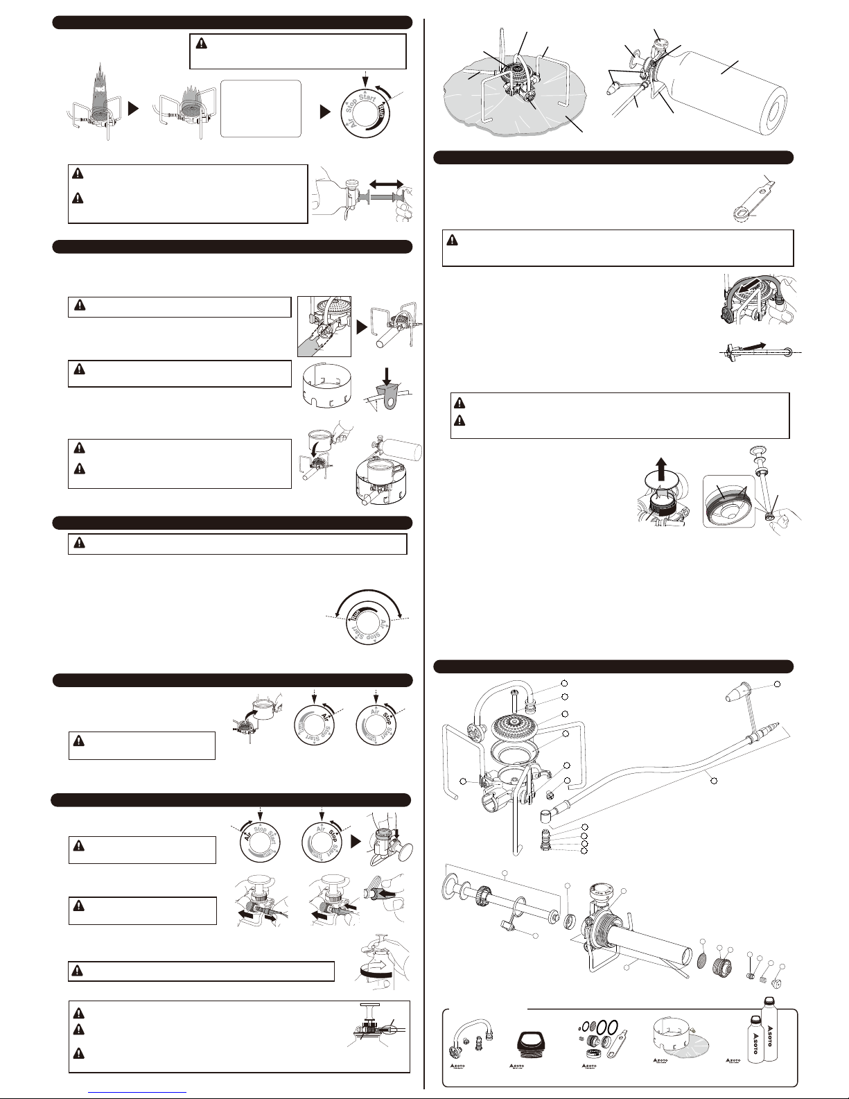
ALWAYS lay the bottle down with the
stabilizer downward. Be sure to lay the
bottle at a 180° angle. (Refer to the
illustration.)
The Control Dial (CD) must ALWAYS be
in the upright, vertical position when unit
is in use. (Refer to the illustration.)
Never place face or other body parts directly over
the stove when lighting.
This initial ignition will significantly reduce pressure
built up inside the bottle. Always make sure to
optimize the pressure inside the fuel bottle before
igniting the stove.
Use of the reflective sheet in the snow: When used with the stove in the snow, the reflective heat may
cause the snow to melt under the sheet, making the base unstable. Be sure to check snow conditions
under the reflective sheet regularly to avoid potential sliding of pots which may be full of hot liquid or food.
Actions marked " " in the illustrations are strictly prohibited.
Preparing
Pumping
Prepare the unit
"DO NOT FILL
ABOVE THIS
LINE" Fuel
Air
When filling the bottle with fuel, keep the fuel and bottle far
away from a lit stove, naked flame, or any heat source.
When inserting the pump, carefully place it into the bottle to avoid damage
of all pipes installed in the pump system.
IMPORTANT!!! Always check the lip on top of the bottle
and the O-ring P-34 on the Smart Pump for wear-and-
tear, including dust, deformation, and cuts. This could
cause the fuel to leak, resulting in fire, bodily injury, and
even death. If dirty, clean the flat lip and the O-ring.
Replace the O-ring if wear-and-tear has occurred. Replace the bottle if the
flat lip is deformed and cuts are found.
NEVER fill fuel above the "DO NOT FILL ABOVE THIS LINE"
mark as the system requires adequate air to ignite. A lack of air
supply may result in failure to ignite.
①
②
③
①
②
Ignition
①IMPORTANT: Confirm that the CD
position is at the "STOP"
position. Then, pull the CD
upward to unlock.
②Prepare a heat source.
③Turn the CD to the “START”
position and ignite. Initial ignition
may produce a strong red leaping
flame.
Output: 4,000 kcal/h 4,650 W 15,800 BTU
Types of fuel: White gasoline only.
Duration: Burns approx. 1 hour at maximum output (1.5 hour at 2,500 kcal/h [10,000BTU])
using 480ml (16.3 oz.) white gasoline.
Weight: 163g (5.7 oz.) without pump, 333g (11.8 oz.) with the pump.
Dimensions when in use (stove body only): 13.5 x 13.5 x 8.0cm (5.3 x 5.3 x 3.1 inches)
Dimensions when stowed (stove body only): 8.0 x 6.5 x 8.0cm (3.1 x 2.6 x 3.1 inches)
The proper procedure for extinguishing a flame is to turn the CD
to the “AIR” position. The “AIR” position will cut off the fuel
supply, allowing only air to release from the Wide Mouth Bottle.
Simultaneously, the air cleans the fuel passageway. This
procedure will also ensure a longer life for the generator unit.
①
②
①②
③
Ignite the gas mixture
made up of fuel and air.
Only air will be released
during the initial 2 to 3
seconds.
SOTO Wide
Mouth Bottle
Conventional
fuel bottle
Hose
Hose
Pump
Plastic
guard
Control Dial(CD)
Burner
head
Pot support
Generator unit
Stabilizer
stand
Fuel bottle
Pressure indicator
Vent
Heat reflective sheet
Lock
Red mark on
the Pressure
Indicator
Unlock
O-ring
P-34
O-ring
P-34
O-ring
P-34
Lip
ATTENTION: Only air will be released during the
initial 2 to 3 seconds after the CD is turned to the
“START” position. Then fuel mixed with air will
appear at the burner head.
Check whether the Backflow Prevention Nozzle (Assembly Drawing 25) is
loose. If loose, tighten with the Multi-tool.
Bottle:
Lay at a 180° angle
CD: in the upright,
vertical position
③
Opening for air
Opening for
intake of fuel
Heat
source
At low temperature, the Pump Shaft Gasket may undergo shrinkage, causing
difficulties in pressurizing the bottle. If this is observed, unscrew the cylinder
cap, remove the pump shaft and bring the Pump Shaft Gasket to body
temperature. Return the units and continue pressurizing the bottle.
Pressure Indicator facilitates the operator by ensuring a successful ignition at each initial operation. The Pressure
Indicator also prevents operator from over-pressurizing the fuel bottle. The Pressure Indicator may not accurately
reflect the exact pressure inside the fuel bottle. The Pressure Indicator will not move in and out according to the
pressure built up or released inside the fuel bottle.
Fuel bottle 1000ml
Filled to the “Do not
fill above this line”
Half filled
Level of
the fuel
700 ml
350 ml
Pumping
strokes
90 times
210 times
Fuel bottle 1000ml
Filled to the “Do not
fill above this line”
Half filled
Level of
the fuel
480 ml
240 ml
Pumping
strokes
70 times
140 times
ART#:OD-1NPENUSA1403
◆Cleaning the Burner Head
①Use part B of the Multi-tool to unscrew the Burner Head Screw +/-M4 x 20.(Refer to Assembly Drawing 2)
②Hold the burner head and use a soft brush to lightly brush the burner head. If necessary, submerge the
burner head in warm water, then use a soft brush to clean. NEVER forcefully clean the burner head as it
may cause the burner head to deform.
③Return the burner head to the stove and screw into place. Never over tighten the screw. Failure to
observe this instruction may cause deformation of the burner head.
◆Maintenance for the pump shaft gasket
①Turn the cylinder cap as shownin the drawing. Then,
take the pump shaft.
②Apply grease to the replaceable pump shaft gasket.
③Return the pump shaft to thepump cylinder and cap
tightly.
●Never disassemble any parts that are not described in this manual. Never modify any
parts of the Muka, Smart Pump, or Wide Mouth Bottle.
● Always use original SOTO parts and replacements for safety. Use of non-SOTO parts
will void the warranty. Alteration and modification will also void the warranty.
● Always carry the Multi-tool and replacement parts.
◆Maintenance of the pot supports
Apply a small amount of lubricating oil to the spring plate (refer to Assembly Drawing 6) and the pot support.
The initial ignition will consume most of the pressure built up inside the Wide
Mouth Bottle. Be sure to add adequate pressure when the CD is set to the
“RUN” position.
The red line on the Pressure Indicator means that the pressure has
adequately built up inside the bottle. NEVER over-pressurize the bottle.
DANGER: Failure to follow this instruction may cause the stove to produce
a dangerous, raw flame.
Continued use of the Muka will eventually reduce its flame output. Testing at SOTO’s labs reveals that after
continuous burning of 20 liters of fuel, output is reduced. This volume of fuel is equivalent to approximately 40
700 ml Wide Mouth Bottles. If the flame output appears to be weak, replace the generator unit (sold separately).
Cleaning the spring (located inside the generator unit) and the nozzle will not resolve the burning performance.
Stabilizing the flame
Care and Maintenance
The generator pipe is made of soft material. NEVER apply excessive pressure or deform it when replacing or
at any time.
The generator unit means the unit combined with the generator pipe and the installed jet. The projectile
direction of the fuel from the nozzle is set at a specific angle. Do not bend or press to modify the generator
pipe and the jet. Do not attempt to unscrew the jet from the generator unit.
View of the generator unit
from above.
Projectile fuel
direction
1. Generator Unit
2. Burner Head Screw +/-M4 x 20
3. Burner Head
4. Burner Base Ring
5. Burner Base
6. Spring Plate
7. Screw +/-M4 x 6
8. Hose Unit
9. O-Ring S-4
10. O-Ring P-3
11. O-Ring P-4
12. Generator Joint
13. Nipple Cap
Muka Stove
①When the initial red flame
transforms into a blue flame, turn
the CD to the “RUN” position.
②Pump to increase pressure as necessary for continued use of the stove. Remember to stop
pumping when thered mark on the Pressure Indicator becomes visible.
Grease
14. Pump Shaft Unit
15. Coupler Cap
16. Replaceable Pump Shaft Gasket
17. O-Ring P-34
18. Pump Unit
19. Pump Filter
20. Backflow Prevention Valve Holder
21. O-Ring 13.8 x 2
22. O-Ring S-3
23. Backflow Prevention Valve
24. Backflow Prevention Valve Spring
25. Backflow Prevention Nozzle
Smart Pump
②
凸凸
The valley between the
two projected dents 凸凸
Grease
Blue flame
Initial red flameInitial red flame Wait about 10 seconds.
Stabilizing the flame
(flame changes to blue),
after ignition may take
more time and is
dependent on ambient
temperature, wind, etc.
Switching the CD from the "START" to "RUN" position prematurely
may occasionally cause a flame to ignite between the burner base
ring and the burner base. (see Assembly Drawing 4 and 5 ) Flame will
extinguish in 20 seconds.
25
24
23
22
21
20
19
17
18
16
15
14
Multi-tool
Assembly Drawings
◆Replacing the generator unit (Sold separately)
Be sure to follow this instruction when replacing the Generator Unit. Failure to
follow this instruction may result in deforming the Generator Unit.
①Use part A of the Multi-tool to remove the Generator Joint (refer to Assembly
Drawing 12).
②Use part B of the Multi-tool to remove Screw +/-M4 x 6.
(refer to Assembly Drawing 7).
③To remove the Generator Unit, gently push the unit as shown in the illustration.
④Replace the old generator unit with a new generator unit. Secure with the Screw
+/-M4 x 6.
Installed Generator Unit at the Burner Head is set slightly loose. The gap will
compensate for the expansion and contraction of the Generator Unit which
dependends on the temperature of the Generator Unit.
⑤Install the Generator Joint.
3
2
1
4
6
78
12
11
10
9
13
5
①
Cylinder
cap
Generator Unit
/ OD-GRN
Muka Pro Windscreen
include Heat reflective sheet
/ OD-WH
Maintenance Kit
/ OD-MKN
Fuel Bottle Cap /
OD-BTC
Parts Kit (Sold separately)
Wide Mouth Fuel Bottle
700 ml / OD-LF480
1000 ml / OD-LF720
A
B
The "RUN" position offers a range of flame control. The operator can
regulate the flame by adjusting the CD.
●There is a delay between adjusting the fuel control dial and the flame's response.
Adjusting the flame to simmering: Observe the simmering flame until it is stabilized.
●The ability to simmer may be slightly affected by atmospheric temperatures as
well as built-up pressure inside the bottle.
●The flame may be extinguished when a large amount of liquid is spilled on the
Generator unit.
●Under windy conditions, the vent on the stove body may draw in the flame,
causing the stove to produce a red flame. To resolve this problem, turn the vent
against the wind.
Be sure to turn the CD to the “RUN” position. The “START” position allows a mixture of fuel and air to release.
If the CD is left on the “START” position, the Wide Mouth Bottle will continue loosing its built-up pressure.
①Remove all cooking utensils from the stove.
②Turn the CD to the “AIR” position. This
position allows air to flow inside the hose
while shutting off fuel flow.
③The flame will be extinguished when all fuel inside the hose is burned off.
Then turn the CD to the "STOP" position.
A large flame will leap out of the burner
head when the CD is turned to the "AIR"
position.
Failure to set the CD to the depressed
position or “LOCK” position cause a fuel
leak during transportation of the unit.
NEVER separate the Smart Pump and Wide Mouth Bottle when there is residual pressure inside the bottle.
Failure to observe this instruction will cause damage to the pump system. It may also cause fuel to spray out
creating a potential fire hazard as well as bodily injuries.
If there is any residual pressure left inside
the bottle, unscrewing the Smart Pump
from the bottle will be difficult.
Taking the Smart Pump out of the Wide Mouth Bottle
Flame Control
Extinguishing the flame
①Turn the CD to the “AIR” position to release
the air pressure from the Wide Mouth Bottle
before the Smart Pump can be unscrewed.
②The CD must be placed in the “LOCK”
position to prevent any accidental fuel
leaks.
③Release hose from the Smart Pump.
④Place plastic caps on the Smart Pump
connector and hose connections.
⑤Unscrew the Smart Pump and extract the pump unit carefully.
⑥Pot support is extremely hot during and after use. Completelycool unit before stowing.
Never screw or unscrew the Smart Pump and the Wide Mouth Bottle when the hose unit is
attached.
Never hold the hose base (illustration A) or the pump connection (illustration B) to screw
or unscrew the Smart Pump from the Wide Mouth Bottle. If the Bottle is pressurized, the
force will cause areas "A" and "B" to break.
A range of flame
control
A
B
Always secure the plastic caps for the hose end and the connection on the Smart
Pump when stowing and moving the Muka.
① ② ③
①
④
②
③
⑤
Installation of the O2 Maximizer and Muka Pro Windscreen
Do not adjust vents while stove is in use. The windscreen is
extremely hot during and after use. Never touch the windscreen until
it is completely cool.
Caution: Avoid cutting body parts such as fingers and palms with the
edges of the O2 Maximizer and Muka Pro Windscreen.
The O2 Maximizer and Muka Pro Windscreen are designed to work exclusively with the Muka Stove.
Be sure to install the O2 Maximizer (as shown in the illustration) onto the stove when using the Pro Windscreen. Use of
the O2 Maximizer increases the supply of fresh air to the stove and improves combustion and burning efficiency. Use of
the O2 Maximizer will also reduce the level of CO emissions when the stove is in use, contributing to a greener
environment for future generations.
①Place the O2Maximizer directly on to the vent of the stove.
②Arrange the windscreen into a cylindrical shape to fit the stove
and pot set. Close vents with the windscreen on the upwind
side. All other vents should be folded slightly outward.
③Use the clip included in the kit to secure the overlay area of the
windscreen walls.
④Place pot on top of the stove.
⑤Place the cylindrical windscreen around the stove/pot set.
Windscreen should sit so the vents are closer to the ground.
Stowing the windscreen: Never fold the windscreen as this may damage the
vents. Always roll the windscreen when stowing.
Use only SOTO approved windscreens with the Muka. Never cover the
fuel with a windscreen. Avoid exposing the fuel to heat. The bottle may
explode if exposed to heat.
When installing the Muka Pro Windscreen, keep a minimum distance
of 2.5 cm (1 inch) between the pot and the windscreen to avoid
producing a red flame. The windscreen may melt if exposed to heat.
②
①
③
④
⑤
Clip
Windscreen
walls
Vent
O2
Maximizer
Lock
Hose
Hose
Pump
Plastic
guard
Control Dial(CD)
Burner
head
Pot support
Generator unit
Stabilizer
stand
Fuel bottle
Pressure indicator
Vent
Heat reflective sheet

Terms of Warranty
Service and Warranty Information
SOTO has made every effort to ensure that this product is in excellent condition. In
the unlikely event of trouble, please refer to the "Troubleshooting and How to deal with"
section of this manual. If you continue to experience difficulties, DO NOT attempt to
repair the product. Return it to your retailer or send it to SOTO at the below address.
Warranty registration card
Detach and Return to SOTO within 30 days of purchase
Please return Registration-OD-1NP to SOTO. Proof of
purchase is required and the warranty is
non-transferable. The warranty does not cover
damage caused by misuse, abuse, accident, or
tampering. A fee will be assessed to repair the product
with such damage. Please contact SOTO by phone or
e-mail to receive a Return Authorization Number (RA)
prior to shipping the damaged product to SOTO.
Shipping cost to SOTO is the purchaser's
responsibility. SOTO will pay the return postage.
SOTO may not repair the product without the warranty
and the product. If the product requiring repair is a gift
and the retailer is unable to repair the product, please
contact SOTO for further information.
1.
2.
There will be a cost for repair for the following conditions,
even if the product is under the warranty period:
3.
Damage resulting from misuse or damage resulting
from the repair or modification of the product.
Damage caused by dropping the product after
purchase. Damage caused during transportation.
Damage caused by fire, earthquake, water, lightening,
salt. Damage caused by any other natural disasters or
pollutions.
The Warranty Registration must be forwarded to
SOTO within a 30 day period after purchase.
In the event that the warranty card is lost, SOTO will
not reissue it.
・
・
・
・
・
Product: OD-1NP, Muka Stove
Lot #: ________________________________________
Warranty period: One year from the date of purchase
Date of purchase: ___________ (Copy of the receipt is required.)
Name: _____________________________________
Address: _____________________________________________
__
City: _______________________ State: _________ Zip: ________
Amount paid: ______________________
Place of purchase:
Store name: _____________________________________
City: _________________, State: _________, Zip: _______
( ) Gift, ( ) SOTO, ( ) Other_____________
If purchases online, URL: ___________________________
Shinfuji Burner CO.,LTD.
SOTO USA Inc.
110 Rustic Place, Eugene, Oregon 97401 USA
Phone: 503-314-5119
[email protected] www.sotooutdoors.com
Other Soto Stove manuals


