Sound Control Technologies Cat5 RemoteCam1-S Series Instruction sheet

CAT5REMOTECAM1-S
REMOTE CAMERA INSTALLATION KITS
OVERVIEW &INSTALLATION GUIDELINES
www.soundcontrol.net Page 1 of 8
28 Knight Street, Norwalk, CT., 06851 Phone (203) 854-5701 Fax (203) 854-5702
© SOUND CONTROL TECHNOLOGIES, INC., 2006 RC1S_04d.DOC-9/1/2006
SOUND CONTROL
TECHNOLOGIES
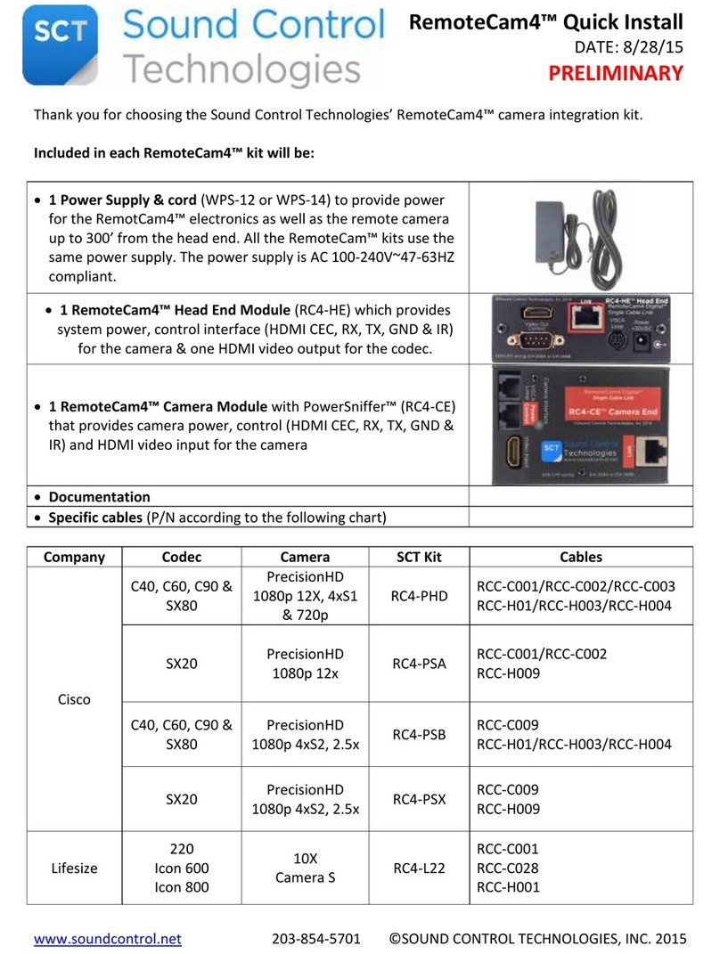
The Cat5 RemoteCam1-S family is offered as a unified electronics platform for cost effective remote Pan Tilt Zoom
(PTZ) camera installations. This system, offered in popular kit form, provides a rugged, high quality wall bracket for
supporting a camera, a universal power supply, molded color coded cable sets and interface electronics.
Regulated camera power, remote control and S-Video are carried on a single standard Cat5 UTP wire for distances
up to 300’1.
Simple Overview
Single Cat5
(Up to 300')
S-Video
Power
Supply
Cat5 I/O Codec
Power In
Head End
USE ONLY
PROVIDED
+30VDC@2A
POWER SUPPLY SOUND CONTROL
TECHNOLOGIES
www.soundcontrol.net
©SCT, 2004
RemoteCam1-SP
Head End
8-Pin mini DIN
Patch Cable
(Video, Power & Control) Control
This technique of integrating PTZ cameras reduces installation hardware and labor for each camera position. All
hardware and cables are available with these kits to cover the most common video and video conferencing
applications for A/V Integrators.
SCT is now offering four complete kits for a wide variety of cameras and optional cable kits for popular video codec
configurations:
Kit Descriptions:
RC1-Sx™ General purpose interface Page 2
(Canon, Elmo & Sony)
RC1-SB™ Sony BRC-3001Page 3
RC1-SP™ Polycom® Powercam™ Page 4
RC1-ST™ Tandberg® Wave-II™2Page 5
Cable Sets:
RC1-Sx™ General purpose cables Page 6
RC1-SB™ Sony BRC-3001Page 6
RC1-SP™ Polycom® Powercam™ Page 6
RC1-ST™ Tandberg® Wave-II™2Page 6
Optional Codec-Specific Cables:
Polycom Codec Selection Guide Page 7
Tandberg Codec Selection Guide Page 7
1Sony BRC-300 currently supports S-Video, power & control up to 100 feet on a single Cat5
2Tandberg Wave-II™ camera control loop limited to manufacturers specification

CAT5REMOTECAM1-S
OVERVIEW &INSTALLATION GUIDELINES
www.soundcontrol.net Page 2 of 8
28 Knight Street, Norwalk, CT., 06851 Phone (203) 854-5701 Fax (203) 854-5702
© SOUND CONTROL TECHNOLOGIES, INC., 2006 RC1S_04d.DOC-9/1/2006
SOUND CONTROL
TECHNOLOGIES
General Purpose Kit SCT part number: RC1-Sx™
Included in this package are:
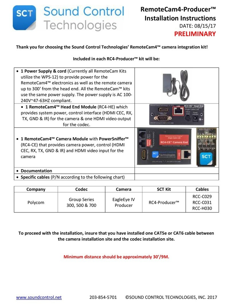
1. Mounting Bracket: This bracket mounts to a standard 2-gang wall box for clean, convenient mounting of the
camera. Typical electrical boxes would be:
a. new construction 2-gang switch box
b. “mud” box
c. old work (retrofit) boxes.
2. Mounting Screw: A thumb screw is provided for attaching the camera to the mounting bracket shelf.
3. Interface Modules: This pair of interfaces provides S-Video, power and control (RX, TX, GND & IR) for the
camera. One small electronics enclosure is required at the rack or head end and a
second module is mounted to the back of the camera mounting plate, housed in the 2-
gang box.
4. Power Supply: The included 30VDC power supply is designed to operate a camera up to 300’ from the
head-end while providing clean, regulated power for safe operation of the camera. 30
Volts from the head end power supply is regulated to 12 VDC at the camera for clean,
reliable operation.
5. Molded Cables: Two molded cables are included in this kit.
a. Sx001 Camera cable is a molded 8-Pin mini DIN plug (White) for the camera
mount electronics that breaks out to a molded S-Video plug (Yellow), 2-Pin
power plug (Black, regulated 12V DC) and 8-Pin mini DIN for control (Black).
b. Sx003 Head end cable is a molded 8-Pin mini DIN plug (Blue) for the head end
electronics that breaks out to a molded S-Video jack (Yellow) and a molded BD9
(Black) for remote control.
Simple RC1-Sx™ System Diagram

CAT5REMOTECAM1-S
OVERVIEW &INSTALLATION GUIDELINES
www.soundcontrol.net Page 3 of 8
28 Knight Street, Norwalk, CT., 06851 Phone (203) 854-5701 Fax (203) 854-5702
© SOUND CONTROL TECHNOLOGIES, INC., 2006 RC1S_04d.DOC-9/1/2006
SOUND CONTROL
TECHNOLOGIES
Sony BRC-300™3SCT part number: RC1-SB™
Included in this package are:
1. Mounting Bracket: This bracket mounts to a standard 3-gang wall box for clean, convenient mounting of the
camera. Typical electrical boxes would be:
a. new construction 3-gang switch box
b. old work (retrofit) boxes.
2. Mounting Screw: A thumb screw is provided for attaching the camera to the mounting bracket shelf.
3. Interface Modules: This pair of interfaces provides S-Video, power and control (RX, TX, GND & IR) for the
camera. One small electronics enclosure is required at the rack or head end and a
second module is mounted to the back of the camera mounting plate, housed in the 3-
gang box.
4. Power Supply: The included 30VDC power supply is designed to operate a camera up to 100’ from the
head-end while providing clean, regulated power for safe operation of the camera. 30
Volts from the head end power supply is regulated to 12 VDC at the camera for clean,
reliable operation.
5. Molded Cables: Two molded cables are included in this kit.
a. Sx001 Camera cable is a molded 8-Pin mini DIN plug (White) for the camera
mount electronics that breaks out to a molded S-Video plug (Yellow), 2-Pin
power plug (Black, regulated 12V DC) and 8-Pin mini DIN for control (Black).
b. Sx003 Head end cable is a molded 8-Pin mini DIN plug (Blue) for the head
end electronics that breaks out to a molded S-Video jack (Yellow) and a
molded BD9 (Black) for remote control.
Simple RC1-SB™ System Diagram
3Sony BRC-300 currently supports S-Video, power & control up to 100 feet on a single Cat5

CAT5REMOTECAM1-S
OVERVIEW &INSTALLATION GUIDELINES
www.soundcontrol.net Page 4 of 8
28 Knight Street, Norwalk, CT., 06851 Phone (203) 854-5701 Fax (203) 854-5702
© SOUND CONTROL TECHNOLOGIES, INC., 2006 RC1S_04d.DOC-9/1/2006
SOUND CONTROL
TECHNOLOGIES
Polycom® Powercam™ SCT part number: RC1-SP™
Included in this package are:
1. Mounting Bracket: This bracket mounts to a standard 2-gang wall box for clean, convenient mounting of the
camera. Typical electrical boxes would be:
a. new construction 2-gang switch box
b. “mud” box
c. old work (retrofit) boxes.
2. Mounting Screw: A thumb screw is provided for attaching the camera to the mounting bracket shelf.
3. Interface Modules: This pair of interfaces provides S-Video, power and control (RX, TX, GND & IR) for the
camera. One small electronics enclosure is required at the rack or head end and a
second module is mounted to the back of the camera mounting plate, housed in the 2-
gang box.
4. Power Supply: The included 30VDC power supply is designed to operate a camera up to 300’ from the
head-end while providing clean, regulated power for safe operation of the camera. 30
Volts from the head end power supply is regulated to 12 VDC at the camera for clean,
reliable operation.
5. Molded Cables: Two molded cables are included in this kit.
a. SP001 Camera cable is a molded 8-Pin mini DIN cable for the camera mount
electronics that connects S-Video, power and control to the Powercam™.
b. Sx003 Head end cable is a molded 8-Pin mini DIN plug (Blue) for the head
end electronics that breaks out to a molded S-Video jack (Yellow) and a
molded BD9 (Black) for remote control.
Simple RC1-SP™ System Diagram
RemoteCam1-S-P
Cable-
SP001
Cat5 I/O
USE ONLY
PROVIDED
+30VDC@2A
POWER SUPPLY
RemoteCam1-SP
Head End
SOUND CONTROL
TECHNOLOGIES
www.soundcontrol.net
©SCT, 2003
Codec
Cable-
Sx003
RemoteCam
Power
Supply
RJ-45
Patch
RJ-45
Patch
S-Video
Camera I/O
Polycom® Powercam™
Control
Polycom® VSX8000™ Main Camera
S-Video
(Dual BNC) Control (DB15-Female)
Polycom® VSX7000e™ Main Camera
S-Video Control (DB15-Female)
DB-9 Female
SP002
DB-9 Female DB-15 Female
SP003
DB-9 Female DB-9 Female
SP004
DB-9 Female DB-15 Female
SP003
SP005
Polycom® VSX 8000 & VSX7000e™ 2nd Camera
S-Video Control (DB9-Male)
Polycom® VSX7000™ & VSX7000s™
2nd Camera
S-Video Control

CAT5REMOTECAM1-S
OVERVIEW &INSTALLATION GUIDELINES
www.soundcontrol.net Page 5 of 8
28 Knight Street, Norwalk, CT., 06851 Phone (203) 854-5701 Fax (203) 854-5702
© SOUND CONTROL TECHNOLOGIES, INC., 2006 RC1S_04d.DOC-9/1/2006
SOUND CONTROL
TECHNOLOGIES
Tandberg® Wave-II™4SCT part number: RC1-ST™
Included in this package are:
1. Mounting Bracket: This bracket mounts to a standard 2-gang wall box for clean, convenient mounting of the
camera. Typical electrical boxes would be:
a. new construction 2-gang switch box
b. “mud” box
c. old work (retrofit) boxes.
2. Mounting Screw: A thumb screw is provided for attaching the camera to the mounting bracket shelf.
3. Interface Modules: This pair of interfaces provides S-Video, power and control (RX, TX, GND & IR) control for
the camera. One small electronics enclosure is required at the rack or head end and a
second module is mounted to the back of the camera mounting plate, housed in the 2-
gang box.
4. Power Supply: The included 30VDC power supply is designed to operate a camera up to 300’ from the
head-end while providing clean, regulated power for safe operation of the camera. 30
Volts from the head end power supply is regulated to 12 VDC at the camera for clean,
reliable operation.
5. Molded Cables: Two molded cables are included in this kit.
a. ST001 Camera cable is a molded 8-Pin mini DIN plug (White) for the camera
mount electronics that breaks out to a molded S-Video plug (Yellow), 2-Pin
power plug (Black, regulated 12V DC) and RJ-45 for control (Black).
b. Sx003 Head end cable is a molded 8-Pin mini DIN plug (Blue) for the head
end electronics that breaks out to a molded S-Video jack (Yellow) and a
molded BD9 (Black) for remote control.
Simple RC1-ST™ System Diagram (typical)
Camera 1 Camera 2
RC1-S™
Not
Used Cable-
ST001
RC1-S™
RJ-
11 RJ-45
Patch
RJ-45
Jack
Cable-
ST002
RJ-45
Patch
Cable-
ST001
Cat5 I/O
USE ONLY
PROVIDED
+30VDC@2A
POWER SUPPLY
RemoteCam1-SP
Head End
SOUND CONTROL
TECHNOLOGIES
www.soundcontrol.net
©SCT, 2003
Codec
Cable-
Sx003
Cat5 I/O
USE ONLY
PROVIDED
+30VDC@2A
POWER SUPPLY
RemoteCam1-SP
Head End
SOUND CONTROL
TECHNOLOGIES
www.soundcontrol.net
©SCT, 2003
Codec
RemoteCam
Power Supply
RemoteCam
Power Supply
RJ-45
Patch
RJ-45
Patch
RJ-45
Patch
RJ-45
Patch
Control
S-Video
Visca OutVisca In S-Video Power 12W
2.5 x 5.5
Tandberg® Wave II™
Visca OutVisca In S-Video Power 12W
2.5 x 5.5
Tandberg® Wave II™
Cable-
Sx003
Not Used
S-Video
Cat5
Cat5
Cat5
4Tandberg Wave-II™ camera control loop limited to manufacturers specification

CAT5REMOTECAM1-S
OVERVIEW &INSTALLATION GUIDELINES
www.soundcontrol.net Page 6 of 8
28 Knight Street, Norwalk, CT., 06851 Phone (203) 854-5701 Fax (203) 854-5702
© SOUND CONTROL TECHNOLOGIES, INC., 2006 RC1S_04d.DOC-9/1/2006
SOUND CONTROL
TECHNOLOGIES
Camera Cables
RC1-Sx™ & RC1-SB™ Kit Cables
Sx001 Camera Cable
4-Pin mini DIN S-Video Plug (Yellow)
8-Pin mini DIN Control (Black)
2-Pin 12 VDC Power
8-Pin mini DIN Unified (White)
Sx003 Head End Cable (standard with all kits)
4-Pin mini DIN S-Video Jack (Yellow)
DB9 Control (Black)
8-Pin mini DIN Unified (Blue)
Optional GPC-1 Camera Control Loop Cable Kit for RC1-Sx™ & RC1-SB™
Sx002 Camera Control Loop Cable
8-Pin mini DIN Control (Red)
8-Pin RJ-45 Jack (Black)
Sx004 Head End Control Loop
DB9 Control (Black)
8-Pin RJ-45 Jack (Black)
Included RC1-SP™ Kit Cables
SP001 Camera Cable
8-Pin mini DIN Camera connection (Black)
8-Pin mini DIN Unified (Black)
Sx003 Head End Cable (standard with all kits)
4-Pin mini DIN S-Video Jack (Yellow)
DB9 Control (Black)
8-Pin mini DIN Unified (Blue)
Included RC1-ST™ Kit Cables
ST001 Wave-II Camera Cable
4-Pin mini DIN S-Video Plug (Yellow)
8-Pin RJ-45 Control (Black)
2-Pin 12 VDC Power
8-Pin mini DIN Unified (White)
Sx003 Head End Cable (standard with all kits)
4-Pin mini DIN S-Video Jack (Yellow)
DB9 Control (Black)
8-Pin mini DIN Unified (Blue)

CAT5REMOTECAM1-S
OVERVIEW &INSTALLATION GUIDELINES
www.soundcontrol.net Page 7 of 8
28 Knight Street, Norwalk, CT., 06851 Phone (203) 854-5701 Fax (203) 854-5702
© SOUND CONTROL TECHNOLOGIES, INC., 2006 RC1S_04d.DOC-9/1/2006
SOUND CONTROL
TECHNOLOGIES
Optional Codec-Specific Cables:
Optional Polycom Codec-Specific Interface Cable Kits
Codec
& Port
VSX-7000
2nd
Camera
VSX-7000s
2nd
Camera
VSX-7000e
Main Camera
VSX-8000
Main Camera
VSX-8000
2nd
Camera
VSX-7000e
2nd
Camera
Control SP002 SP002 SP003 SP003 SP004 SP004
Video Sx005 Sx005 Sx005 SP005 Sx005 Sx005
Cable Set VSX-1 VSX-1 VSX-2 VSX-3 VSX-4 VSX-4
Optional Polycom Codec-Specific Interface Cables
SP002
VSX-7000 2nd Camera
VSX-7000s 2nd Camera
DB9 to 8-Pin mini DIN
SP003
VSX-7000e Main Camera
VSX-8000 Main Camera
DB9 to DB-15
SP004
VSX-8000 2nd Camera
VSX-7000e2nd Camera
DB9 to DB9
SP005
VSX-8000 Main Camera
4-Pin mini DIN to x2 BNC
Sx005
S-Video patch cable
4-Pin mini DIN to 4-Pin mini DIN
Optional Tandberg Codec-Specific Interface Cable Kits
Codec
& Port
770, 880, 990
2nd Camera
3000MXP
Main Camera
3000MXP
2nd Camera
6000MXP
Main Camera
6000MXP
2nd Camera
Control ST003 ST004 ST003
Video Sx005 Sx005 Sx005 Sx005
Control Loop ST002 ST002
Cable Set MXP-1 MXP-3 MXP-2 MXP-1 MXP-2
Optional Tandberg Codec-Specific Interface Cables
ST002 Camera Control Loop Cable
6-Pin RJ-11 Plug Control Loop (Red)
8-Pin RJ-45 Control Jack (Black)
ST003
Straight thru serial cable
DB9 to DB9
ST004 3000MXP Main Camera
Unified S-Video & Control
8-Pin mini DIN to DB9
Used in place of Sx003

CAT5REMOTECAM1-S
OVERVIEW &INSTALLATION GUIDELINES
www.soundcontrol.net Page 8 of 8
28 Knight Street, Norwalk, CT., 06851 Phone (203) 854-5701 Fax (203) 854-5702
© SOUND CONTROL TECHNOLOGIES, INC., 2006 RC1S_04d.DOC-9/1/2006
SOUND CONTROL
TECHNOLOGIES
Technical Specifications:
Technical specifications are subject to change. This information applies to a product under development;
specifications are subject to change without notice.
Camera Interface:
Unified Jack: 8-Pin mini DIN (break out cables are version specific, supplied)
Video Input:
S-Video
Control RS-232 I/O RX, TX, GND & IR
Power Output +12VDC @ 1.3A Max
Head-End Interface:
Unified Jack: 8-Pin mini DIN (break out cable supplied)
Video Output:
S-Video
Connector 4-Pin mini DIN Jack
Control:
RS-232 I/O & IR Out
Connector DB-9 Female (RX, TX, GND) & IR Out
Power Input:
+30VDC @ 2.0A Max
Connector 2 Pin Circular 5.5 x 2.5mm
Power Requirements: +30VDC, 2.0A
External Universal AC Input Supply Included
Size: H 0.75", W 1.5", D 2.5"
Weight:
1.0 lbs.
For the original equipment supplier, custom configurations of the Series II ASP-8x8 Audio Matrix™, Acoustic Echo
Cancellation, Microphone Mixers, Camera Control Products and other SCT equipment are available. Please contact
SCT for details on pricing and availability.
Please note that many other cameras, cables and codecs may be supported. Please contact SCT or your local
representative for more information.
All Trademarks are the property of their respective owners. No claim is made to any marks other than those expressly
the property of Sound Control Technologies, Inc.
Table of contents
Other Sound Control Technologies Camera Accessories manuals
Popular Camera Accessories manuals by other brands

Battery Power Solutions
Battery Power Solutions Freedom CPAP Battery user manual

Sunpak
Sunpak Sunpak PRO 723PX operating instructions
Oben
Oben AC-2300 series user manual
TQ
TQ Remote V01 user manual

Sanyo
Sanyo UF553450L Specifications

Digital Concepts
Digital Concepts PORTABLE LIGHT STUDIO PS-101 user manual
