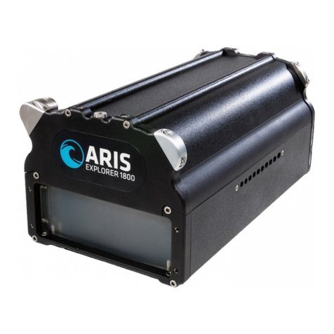
Sound Metrics ARIS EXPLORER User manual

Getting Started
ARIS EXPLORER

1
TABLE OF CONTENTS
ARIS EXPLORER GETTING STARTED MANUAL
2 DISCLAIMER
3 ARIS EXPLORER: INTRODUCTION OF THE SONAR
Features
ARIS Explorer 3000
ARIS Explorer 1800
ARIS Explorer 1200
5 WHAT’S IN THE BOX?
Inside the Transit Case
Inside the Waterproof Box
9 PARTS OF THE ARIS EXPLORER SYSTEM
ARIS Explorer
Command Module
11 SETTING UP THE EXPLORER
15 IMAGING WITH THE EXPLORER
Orienting the Explorer
Imaging Example
Acoustic Volume
Range, Cross-Range & Image Perspective
19 INTRODUCTION TO ARIScope
Installing ARIScope
20 ARIScope Basics
Main Elements of the User Interface
Top Bar
23 APPENDIX
24 SPECIFICATIONS
Technical Specifications
Provided Power Supply
Power Consumption
PC Requirements
Recommended PC Configuration
25 MOUNTING DIMENSIONS
ARIS Explorer 3000
ARIS Explorer 1800 & 1200
26 MAINTENANCE
Anode Inspection
Cable Connector Care
Lens Bubbles
Lens Housing Removal
How to Install Silt Plugs
33 COMMAND MODULE
Troubleshooting
Status Codes
35 ACCESSORIES
37 NOTES
38 WARRANTY INFORMATION
40 CONTACT US

2
DISCLAIMER
PLEASE READ THE ENTIRE MANUAL BEFORE USING THE ARIS EXPLORER
!
• IMAGES SHOWN IN THE MANUAL ARE FOR REPRESENTATIONAL PURPOSES ONLY; ACTUAL APPEARANCE OF PRODUCTS MAY VARY
• SOUND METRICS RESERVES THE RIGHT TO CHANGE ANY INFORMATION IN THIS MANUAL WITH OR WITHOUT NOTIFICATION
WARNING:
• MISUSE OF EQUIPMENT CAN RESULT IN SAFETY HAZARDS
• DO NOT POWER ON SYSTEM WITHOUT FULLY ENGAGING ALL
CONNECTORS - CONNECTORS MUST BE FIRMLY TIGHTENED BY HAND
UNTIL CONNECTOR STOPS TURNING AND PROVIDED GAUGE CAN NOT
FIT BETWEEN CONNECTOR GAP
• DO NOT DISCONNECT CABLES WHILE SYSTEM IS UNDERWATER
OR POWERED ON; POWER MUST BE OFF BEFORE DISENGAGING
CONNECTORS
• DO NOT OVERTIGHTEN SCREWS; OVERTIGHTENING SCREWS CAN
DAMAGE UNIT - APPROVED TORQUE IS AS FOLLOWS:
2.5 Nm— M4 SCREWS, 5 Nm— M5 SCREWS, AND 25 Nm— M8 SCREWS
• DO NOT ATTEMPT TO REPAIR EQUIPMENT
• FAILURE TO FOLLOW ABOVE INSTRUCTIONS WILL VOID WARRANTY
CAUTION:
GAUGE NO LONGER FITS BETWEEN CONNECTOR GAP

3
ARIS EXPLORER
• Dynamic Focus Using Dual Frequency
• Unprecedented High-Definition Imagery
• Capable of Imaging at Close Range
• Built in Compass and Depth Gauge
• Optional Longer Range Applications -
Three Models from which to Choose
FEATURES
ARIS EXPLORER: INTRODUCTION OF THE SONAR

4
ARIS EXPLORER: INTRODUCTION OF THE SONAR
ARIS EXPLORER 3000
IDENTIFICATION MODE
Identification Frequency: 3.0 MHz
Range: 5 m
DETECTION MODE
Detection Frequency: 1.8 MHz
Range: 15 m
ARIS EXPLORER 1800
IDENTIFICATION MODE
Identification Frequency: 1.8 MHz
Range: 15 m
DETECTION MODE
Detection Frequency: 1.1 MHz
Range: 35 m
ARIS EXPLORER 1200
IDENTIFICATION MODE
Identification Frequency: 1.2 MHz
Range: 35 m
DETECTION MODE
Detection Frequency: 0.7 MHz
Range: 80 m

5
INSIDE THE TRANSIT CASE
PRODUCT PART #
ARIS Explorer 3000,
ARIS Explorer 1800, or
ARIS Explorer 1200
021001
021002
021003
15 m ARIS Cable 013534
Waterproof Box 013410
Command Module 013470
Getting Started Manual 015045
WHAT’S IN THE BOX?

6
WHAT’S IN THE BOX?

7
WHAT’S IN THE BOX?
INSIDE THE WATERPROOF BOX
PRODUCT PART #
Connector Gauge 015872
Software USB Drive 014385
M5 x 10 mm Screws (x8) 014945
Fix It Sticks (x2) 016265
Silicone Spray 015043
Silt Protection Strip 016264
Power Supply 015046
AC Power Cable 016268
Ethernet Cable 014512

8
WHAT’S IN THE BOX?

9
ARIS EXPLORER
PARTS OF THE ARIS EXPLORER SYSTEM
CONNECTOR - Connects the sonar to ARIS Cable
Note: Always be sure connectors are fully engaged
before submerging underwater
LENS - Focuses sound into a high resolution image
SILT PLUG HOLES - Mounts Silt Plug Strips

10
PARTS OF THE ARIS EXPLORER SYSTEM
COMMAND MODULE
The Command Module monitors the power and
connection status of the sonar. The ring-shaped LED
around the main power switch gives visual feedback on
the current operating state of the system.
See Page 34 for the primary status indications of the
Command Module.

11
SETTING UP THE EXPLORER
STEP 1
Attach the bronze nut of the ARIS Cable to
the ARIS Explorer, making sure to line up the key in the
cable with the keyway on the connector. Push in while
tightening the ARIS Cable.
STEP 2
Attach the stainless threaded end of the ARIS Cable to the
Command Module, making sure to line up the key in the
Command Module connector with the keyway on the cable
connector. Push in while tightening the nut on the Command
Module.
Note: To tighten or loosen the nut, turn the nut in the direction
indicated on the Command Module.

12
SETTING UP THE EXPLORER
STEP 3
Using the edge of the Connector Gauge, check that the connectors are mated. The Gauge will no longer slide into the
connector gap when fully engaged.
Note: Gently wiggling the cable while turning the bronze nut will aid in tightening the connector.

13
SETTING UP THE EXPLORER
STEP 4
Pull the waterproof plugs out of the Command Module. Line up the red dot on the Ethernet Cable connector
with the red dot on the receptacle on the Command Module. Push in the connector until it is locked into place.
Connect the Power Supply to the Command Module.
Note: To release the connector, pull the sleeve on the silver connector back until it slips out of the receptacle.

14
SETTING UP THE EXPLORER
STEP 5
Press the center button on the Command Module to power on the ARIS Explorer. The blue light will flash a few times
before remaining steady.
Note: Press the button on the Command Module again to power down the ARIS Explorer.

15
IMAGING WITH THE EXPLORER
Multiple beams directed from the ARIS Explorer
create a fan of narrow slices that form the “acoustic
wedge.” Each individual slice produces a section
of the image, where information in range is then
placed appropriately with neighboring information
in cross-range to produce the entire image.
ORIENTING THE EXPLORER
Orient the Explorer such that the acoustic wedge
covers the object. The surface is shown in range
and cross-range.
Note: The image perspective of the ARIS is 90º
from the aim.
RANGE
ARIS
CROSS-RANGE

16
IMAGING EXAMPLE
The ARIS image shows range and cross-range information from an apparent top-down perspective.
RANGE
CROSS-RANGE
IMAGING WITH THE EXPLORER

17
IMAGING WITH THE EXPLORER
The following illustrations demonstrate how to image an object lying on a surface using the ARIS Explorer:
ACOUSTIC VOLUME
The ARIS Explorer uses multiple beams to project a wedge-shaped volume of acoustic energy, much like a flashlight
projects a cone-shaped volume of light.
ARIS

18
RANGE, CROSS-RANGE & IMAGE PERSPECTIVE
Range, cross-range, and perspective are relative to the acoustic wedge. Each of these are at 90º to the other two,
much like three edges that come together at the corner of a box.
RANGE - Distance away from the ARIS along the length of the wedge
PERSPECTIVE VIEW
ARIS
CROSS-RANGE
RANGE
CROSS-RANGE - Distance directly across the width of the wedge
PERSPECTIVE - Apparent top-down view of transmitted image
IMAGING WITH THE EXPLORER

19
INTRODUCTION TO ARIScope
INSTALLING ARIScope
Un-install any previous version of ARIScope. Open the ARIScope installer file from
the USB drive or downloaded from the Sound Metrics portal. Follow the install
prompts to install the latest version of the software to the PC. Connect to the ARIS,
hover the mouse over the sonar icon, and click Update Sonar.
Note: Your computer may need to restart to complete the installation process.
Manual and automated controls are simple using the ARIScope software
interface. The latest ARIScope is available for download by logging in to
the Sound Metrics portal at:
www.soundmetrics.com/My-Account/Downloads/Customers/Software/ARIS
This manual suits for next models
6
Table of contents
Other Sound Metrics Sonar manuals
