Sound Skulptor CP5176 User manual
www.soundskulptor.com
Document revision 1.3 – Last modification : 26/03/17
P5176 Assembly guide
Safety warning
The kits are main powered and use potentially lethal voltages. Under no circumstance should someone undertake the
realisation of a kit unless he has full knowledge about safely handling main powered devices.
Please read the “DIY guide” before beginning.
Print or open the following documents :
• P5176 Schematics
• P5176 omponents layout
• P5176 Parts list
• P5176 Setup guide
Follow this guide from item number 1 till the end, in this order. The assembly order is based on components height, from
low to high profile, in order to ease the soldering process : The component you are soldering is always taller than the
previously assembled ones and it is pressing nicely against the work area foam.
P5176 Assembly guide – Main P B
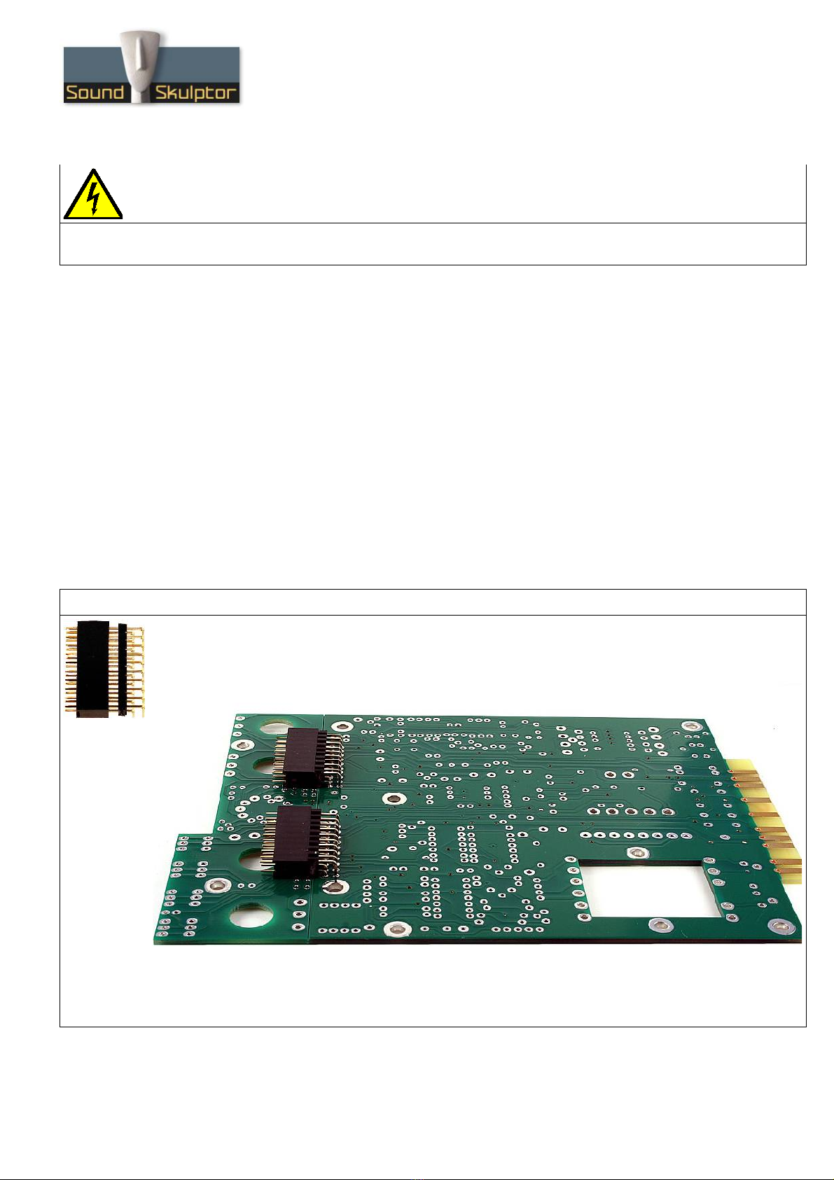
1. P B to P B connectors
Insert the male, 90° angled, 2x10 connectors into the corresponding 2x10 sockets and put them in
place, flat under the P B. Solder.
Warning : The connectors are installed
on the solder side
of the P B.
Warning : It is important not to split the P B before this step as the small P B is used to line up the
connectors horizontally.
opyright ©2013 to Today SoundSkulptor
www.soundskulptor.com
Document revision 1.3 – Last modification : 26/03/17
P5176 Assembly guide – Main P B
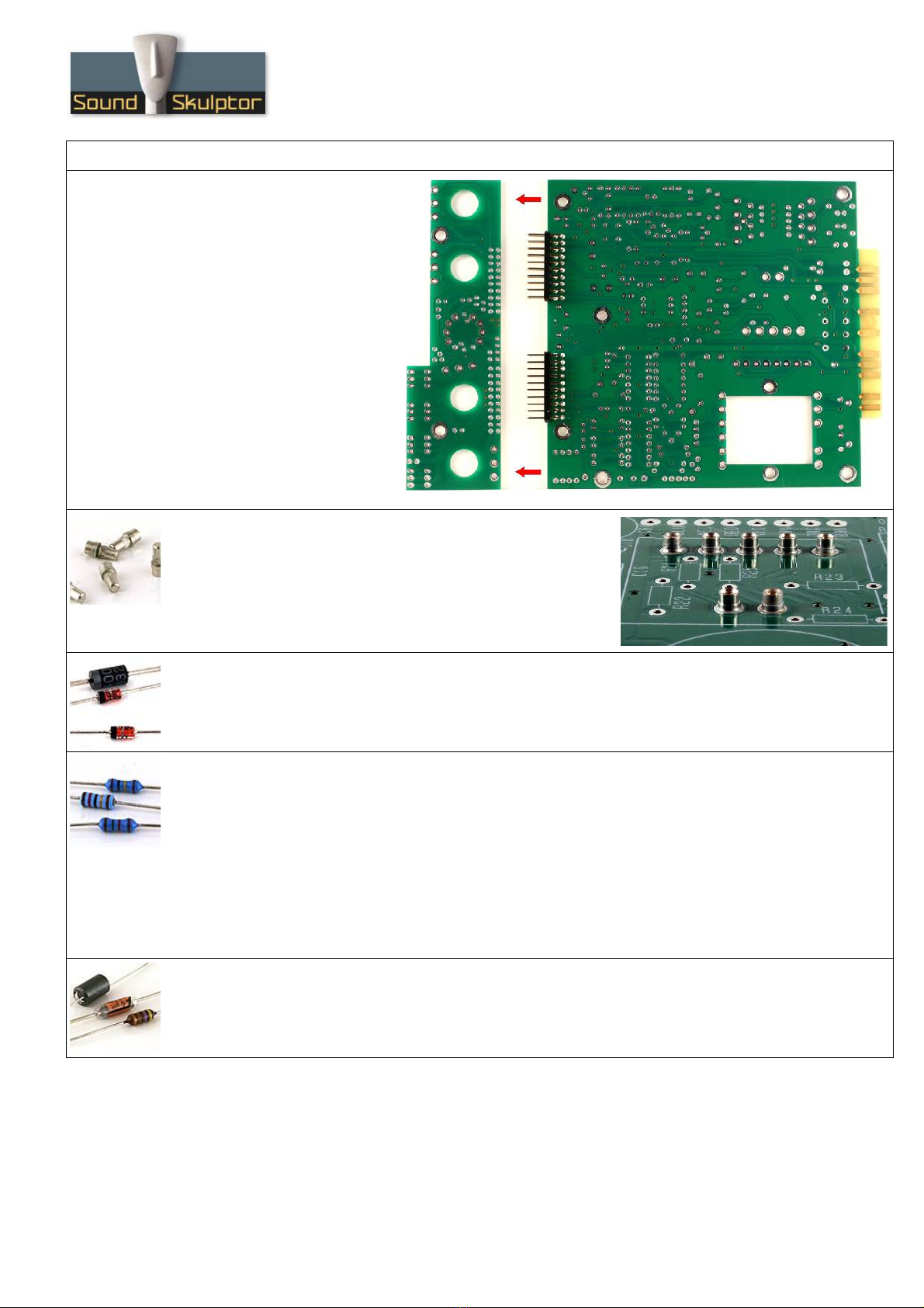
2. P B split
Split the P B along the groove,
taking care not to press on the
connectors.
3. DOA Pin Sockets
Solder the 7 pin sockets for the DOA. Solder one at a time.
Insert one socket, turn over the P B and press against a solid
but flexible surface like cork or dense foam then solder. The
correct positioning of the sockets is very important for easy
insertion of the DOA.
4. Diodes
Add D1, D4 to D7. Use a lead forming tool to bend the leads at 0.4”.
Warning : Make sure to respect the direction of the diodes which is marked by a ring on the component
and a double line on the P B marking.
5. Resistors
Add R3 to R66. The resistors marked N in the parts-list should not be installed.
ontrol the resistor values with a digital multimeter. Bend the leads at 0.4” with a lead forming tool.,
except for R29 which is bent at à 0.6”.
Warning : It is very important to check the resistors value with a DMM because the colour code can be
ambiguous. For example 1K (brown-black-black-brown-brown) can be confused with 110R (brown-brewn-
black-black-brown).
Warning : Resistors R51 (6K8) and R52 (1K) are 0.1% precision resistors. They must not be confused
with 1%, same value resistors. Their last colour ring is violet instead of brown.
6. Inductor
Add L1. Bend at 0.7”.
opyright ©2013 to Today SoundSkulptor
www.soundskulptor.com
Document revision 1.3 – Last modification : 26/03/17
P5176 Assembly guide – Main P B
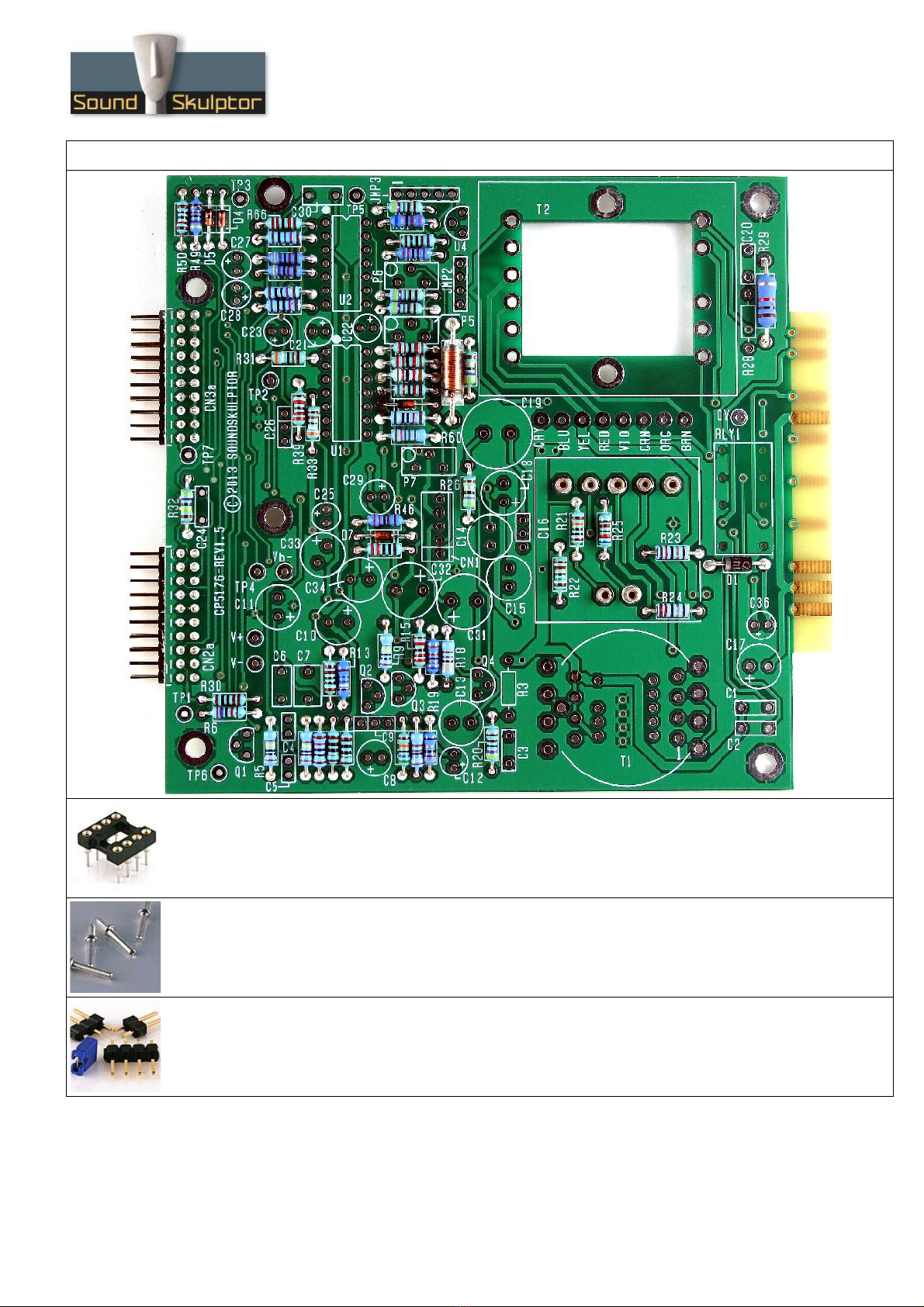
7. I Sockets
Insert and solder the 14 pins sockets of UI and U2.
Warning : Make sure to respect the socket direction, marked by a notch.
8. Test pins
Solder the 11 test pins TP1 to TP7, V+, V-, Vb- and 0V.
9. Jumper headers
Solder the jumper header JMP2, JMP3 (there is no JMP1). Solder one pin first, check verticality, then
solder the other pins.
opyright ©2013 to Today SoundSkulptor

www.soundskulptor.com
Document revision 1.3 – Last modification : 26/03/17
P5176 Assembly guide – Main P B
10. eramic capacitors
Add 9, 16, 26.
Warning : Some capacitors have provision for 2 sizes. Small size capacitors
must be inserted in the correct holes as shown in the picture.
11. Film capacitors
Add 4, 5, 1, 2, 24, 6, 30, 7.
12. Transistors and regulators
Add Q1 to Q4 and U4.
Warning : Watch out the transistor direction.
13. Trimmer potentiometer
Add P5, P6, P7. These 3 trimmers are different from each other. Solder one pin, check verticality then
solder the other pins.
14. onnecteur
Add N1. Solder one pin, check verticality then solder the other pins.
15. Relay
Add RLY1.
16. Electrolytic capacitors
Add 12, 21, 22, 23, 25, 27, 28, 36.
Add 8, 29, 10, 13, 14, 15, 11, 17, 18, 33, 34.
Add 31, 32.
Solder one lead first, adjust verticality then solder the second lead.
33 is larger than on the P B silkscreen but fits without problem. The + (long lead) to the right.
Warning : The +lead must go into the +hole. Do not reverse (they may explode !)
17. Input transformer
It is necessary to leave a small gap between the transformer and the P B surface in order to avoid any
electrical contact between the metal case and pads. Fit a piece of double sided adhesive tape under the
transformer, between the pins. It is not necessary to remove the second protective layer from the tape
as it is only used as a spacer.
Pin 1 on the transformer is identified by a red dot. Insert the transformer, pin 1 into hole number 1.
Start soldering 2 opposite pins, check the position, adjust if necessary then solder the other pins.
Warning : Double check the pin 1 position because this transformer can be mounted backwards!
opyright ©2013 to Today SoundSkulptor

www.soundskulptor.com
Document revision 1.3 – Last modification : 26/03/17
P5176 Assembly guide – Main P B
18. Output transformer
The transformer is mounted using two 25mm M3 screws inserted
from the back of the board. Two metal washers are fitted on each
screw to prevent the transformer touching the P B. One more
washer is used before the nut to protect the lams.
Shorten the leads to the necessary length, around 6 cm. Strip on
5mm and tin. Insert in the pad hole and bend the tinned tip flat on
the pad before soldering. ut flush.
19. Large electrolytics
Add 19. Solder one lead first, adjust verticality then solder the second lead.
20. I 's
Insert U1 and U2 in their sockets. It is necessary to bend the pins slightly inward before inserting.
Attention : Make sure to insert the I 's in the correct direction which is indentified by a notch.
21. Jumpers
Insert two jumpers on JMP2 and one jumper on JMP3 (between pins 1 & 2).
22. Gain reduction meter spacers
Insert a M3x10 mm screw from below P B, add
two metal washers and the 20mm spacer.
Repeat for the second spacer.
opyright ©2013 to Today SoundSkulptor
Nut
Transformer
P B
1 Washer
2 Washers
2 Washers
Spacer
M3x10 mm screw

www.soundskulptor.com
Document revision 1.3 – Last modification : 26/03/17
P5176 Assembly guide – Main P B
23. Visual check
Brush the solder side with a hard tooth brush to remove any remaining solder bits.
Make a full visual check. Any missing component on the board ? Any remaining component in the box ?
When everything looks correct, proceed with the front P B assembly.
P5176 Assembly guide – front P B assembly
1. Resistors
Add R14, R34... R38, R42... R45.
ontrol the resistor values with a digital multimeter. The resistors are installed vertically.
opyright ©2013 to Today SoundSkulptor
www.soundskulptor.com
Document revision 1.3 – Last modification : 26/03/17
P5176 Assembly guide – front P B assembly
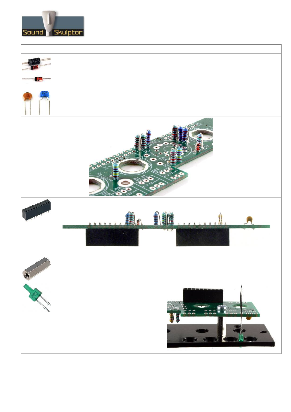
2. Diode
Add D3.
Warning : Make sure to respect the direction of the diode which is marked by a ring on the component
and letter K on the P B marking.
3. eramic capacitor
Add 35.
4. onnectors 2x10
Solder the two 2x10 connectors on the back of the P B, inserted from the solder side.
5. Spacers
Attach two 15 mm spacers with two M3x6 mm screws, inserted from the solder side.
6. 2mm LED
Insert the 2mm LED, taking care of the
anode/cathode position. The shortest leg (cathode)
is the closest to the P B edge. Temporarily
attach the front panel with two M3x8 mm screws.
Adjust the LED flush with the front panel surface.
Solder.
Remove the front panel.
opyright ©2013 to Today SoundSkulptor
www.soundskulptor.com
Document revision 1.3 – Last modification : 26/03/17
P5176 Assembly guide – front P B assembly
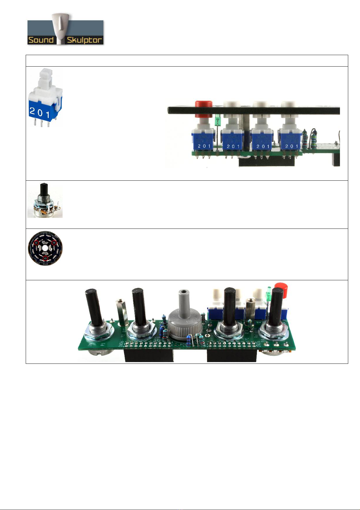
7. Push buttons
Insert the caps on the push buttons. Insert the push buttons, flat, in the correct direction and solder
only one pin.
Warning : The push button direction
is given by digits 2 0 1, engraved
on one side of the switch. Match
the digits with the ones on the
P B.
Install the front panel temporarily
and check the position of the
switches. When all is correct, with
the caps well centred in the front
panel holes, Solder the other pins.
8. Potentiometers
Add P1, P2, P3 and P4. Insert the potentiometers into the P B holes from the solder side, making sure
the pins fit into the corresponding P B pads. Attach with washer and nut on the component side, tighten
firmly to ensure a perfect perpendicular position and solder.
Warning : The 4 potentiometers have different values.
9. Rotary switch
Add the 6 positions rotary switch RSW1.
Warning : The position of the switch is critical for a good front-plate matching. The switch rests on 3
small feet that must sit perfectly flat on the P B. Press the switch on the P B and solder two opposed
pins. heck position then solder the other pins.
opyright ©2013 to Today SoundSkulptor

www.soundskulptor.com
Document revision 1.3 – Last modification : 26/03/17
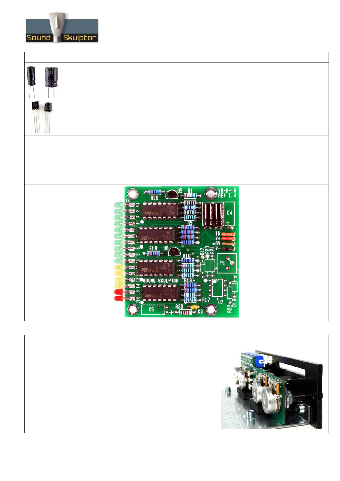
P5176 Assembly guide – Gain reduction meter
1. LEDs
For each one of the 16 LED's cut the short leg (cathode)
at 5mm from body and cut the long leg (anode) at 6mm.
Then insert the first green LED on the P B, long leg (anode) on top. Make sure that
the leg is perfectly parallel to the pad. Solder the anode but leave the cathode free
for now. The position is still easy to adjust until both legs are soldered.
Insert and solder the next LED and repeat until the16 LEDs are in position.
Make a last visual check and correct LED's that are not perfectly lined up, then
solder the cathodes on the P B back side.
2. Straps
Solder the 3 straps indicated in red on the layout schematic. Use
resistors legs that were previously cut.
3. Resistors
Add R1 to R23.
The resistors marked N in the parts list are not installed.
ontrol the resistor values with a digital multimeter. Bend the leads at 0.4” with a lead forming tool.
4. Integrated ircuits
Insert U1, U2, U3 and U4 and solder. You will need to bend the pins slightly inwards before inserting.
Warning : Make sure to respect the I direction, marked by a semi-circular notch on the I and a dot on
the P B.
5. eramic capacitor
Add 3.
opyright ©2013 to Today SoundSkulptor
www.soundskulptor.com
Document revision 1.3 – Last modification : 26/03/17
P5176 Assembly guide – Gain reduction meter
6. Electrolytic capacitors
Add 1, 2.
Warning : The +lead must go into the +hole. Do not reverse (they may explode !)
7. Regulator I 's
Add U5 and U6. Press the I 's down as far as possible in order to keep the components height low.
Warning : Watch out the I direction.
8. Wiring
Install and solder the wires that come from the driving board. The wires are inserted from below the card
through 4 holes and from top into 4 pads for soldering.
If the driving board is the Stereo Tape Simulator, connect orange to IN, red to V+, Brown to 0V, black
to V- and remove the yellow wire.
P5176 Assembly guide – Final assembly
9. Front panel and Side plate assembly
Attach the potentiometers P B to the front panel with two
M3x8 black screws (hex screws).
Attach the side plate to the front panel with two M3x8 black
screws (hex screws).
opyright ©2013 to Today SoundSkulptor

www.soundskulptor.com
Document revision 1.3 – Last modification : 26/03/17
P5176 Assembly guide – Final assembly
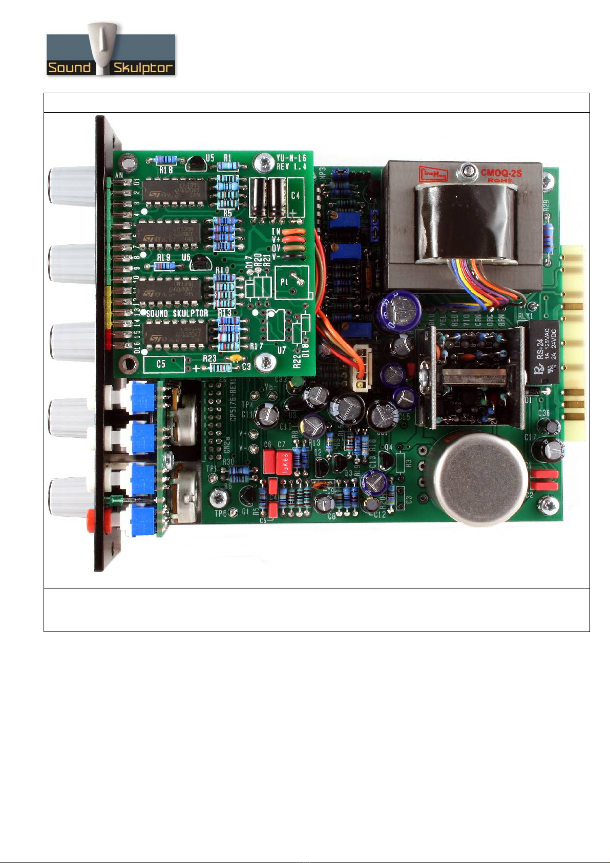
10. Main P B assembly
Insert the main P B connectors into the connectors of the potentiometers P B until match of the main
P B holes with the side plate standoffs.
Attach the main P B with four M3x6 screws and four shake-proof washers
11. Knobs
Attach the 5 knobs to the 5 potentiometers and switch spindles.
12. Gain reduction meter assembly
Attach the GR meter on the two spacers with two M3x6 screws, making a loop with the cable under the
P B. Don't plug the cable yet.
13. Test and setup
It is time for test and setup. Follow instructions on cp5176-setup-guide.pdf.
opyright ©2013 to Today SoundSkulptor
www.soundskulptor.com
Document revision 1.3 – Last modification : 26/03/17
P5176 Assembly guide – Final assembly
14. ongratulations !
You're done !
opyright ©2013 to Today SoundSkulptor
Other manuals for CP5176
1
Table of contents
Other Sound Skulptor Compressor manuals


Popular Compressor manuals by other brands


EKOM
EKOM DK50 4x2VT/M user manual

Panasonic
Panasonic Matsushita DD57C94GBU6 Specification sheet

Scheppach
Scheppach HC 53dc Operating and safety instructions

Ingersoll-Rand
Ingersoll-Rand P90 Operation and Maintenance Manual with Parts Catalogue

Campbell Hausfeld
Campbell Hausfeld HL5401 Series Quick setup instructions

GEA
GEA HG44e/475-4 S Translation of the original instructions


