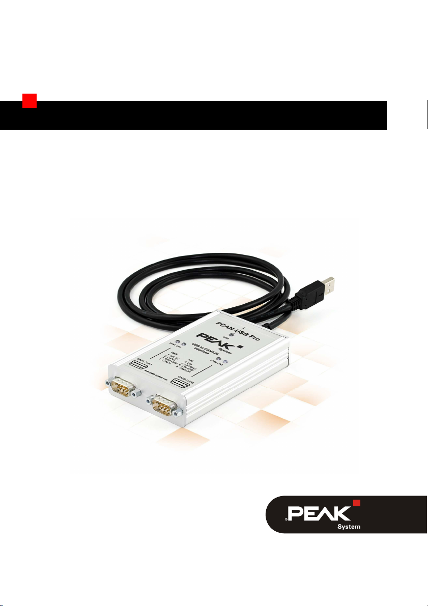
Peak PCAN-USB Pro User manual

PCAN-USB Pro
High-speed USB 2.0 to
CAN/LIN Interface
User Manual
V2.1.4

PCAN-USB Pro – User Manual
2
Product Name Model Part number
PCAN-USB Pro IPEH-002061
CANopen® and CiA® are registered community trade marks of CAN in Automation
e.V.
All other product names mentioned in this document may be the trademarks or
registered trademarks of their respective companies. They are not explicitly marked
by “™” or “®”.
© 2012 PEAK-System Technik GmbH
PEAK-System Technik GmbH
Otto-Roehm-Strasse 69
64293 Darmstadt
Germany
Phone: +49 (0)6151 8173-20
Fax: +49 (0)6151 8173-29
www.peak-system.com
info@peak-system.com
Document version 2.1.4 (2012-07-16)

PCAN-USB Pro – User Manual
3
15
1.1 Properties at a Glance 5
1.2 System Requirements 6
1.3 Scope of Supply 7
28
3
3.1 D-Sub Connector CAN 10
3.2 D-Sub Connector LIN 11
3.3 Supplying External Devices via the D-Sub
Connector 11
3.4 Cabling 13
3.4.1 Termination 13
3.4.2 Example of a Connection 13
3.4.3 Maximum Bus Length 14
4
4.1 Status LEDs 15
4.2 Unplugging the USB Connection 16
4.3 Distinguishing Several PCAN-USB Pro Adapters 16
5
5.1 CAN Monitor PCAN-View for Windows 17
5.1.1 Receive/Transmit Tab 19
5.1.2 Trace Tab 21
5.1.3 PCAN-USB Pro Tab 22
5.1.4 Bus Load Tab 23
5.1.5 Error Generator Tab 24
5.1.6 Status Bar 25
5.2 LIN Monitor PLIN-View Pro for Windows 26

PCAN-USB Pro – User Manual
4
5.2.1 Receive/Transmit or Receive/Publisher
Tab 28
5.2.2 Trace Tab 30
5.2.3 Status Bar 31
5.3 Linking Own Programs with PCAN-Basic 32
5.3.1 Features of PCAN-Basic 33
5.3.2 Principle Description of the API 34
5.3.3 Notes about the License 35
5.4 Linking Own Programs with the PLIN-API 36
6

PCAN-USB Pro – User Manual
5
1
The PCAN-USB Pro adapter enables simple connection of a PC to
CAN and LIN networks. Two field busses can be connected at the
same time, with up to four connections available using appropriate
adapter cables (2x CAN, 2x LIN). Its robust aluminium casing makes
the PCAN-USB Pro adapter suitable for mobile applications. Soft-
ware interfaces exist for different operating systems, so programs
can easily access a connected CAN and/or LIN bus.
Tip: At the end of this manual (Appendix C) you can find a
Quick Reference with brief information about the installation
and operation of the PCAN-USB Pro adapter.
Adapter for USB port (USB 2.0)
Transmitting and receiving of CAN and LIN messages using
2 D-Sub connections (both with pin assignment for CAN and LIN
bus)
Time stamp resolution 1 μs
Extended operating temperature range -40 - 85 °C (-40 - 185 °F)
Bit rates up to 1 Mbit/s
Fulfils CAN specification 2.0A and 2.0B
MAX3057ASA CAN transceiver
Each CAN channel is separately opto-decoupled against USB
and LIN

PCAN-USB Pro – User Manual
6
Measurements of bus load including error frames and overload
frames
Induced error generation for incoming and outgoing CAN
messages
Bit rates of 1 - 20 kbit/s
AMIS-30600 LIN transceiver
Both LIN channels (common Ground) are opto-decoupled
against USB and CAN
Can be used as a LIN master or slave (1 ms master task
resolution)
Automatic bit rate, frame length, and checksum type recognition
Autonomous scheduler with support for unconditional, event
frames, and sporadic frames
Hardware can work through a schedule table (up to 8 tables can
be configured with a total of 256 slots
Operating system Windows 7/Vista/XP (32/64-bit)
or Linux (32/64-bit)
A vacant USB port (USB 2.0 recommended) at the computer or
at a USB hub connected to the computer
For LIN operation: supply voltage 8 to 18 V for the LIN
transceiver (e.g. car battery)
Note: Do not use a USB extension cable to connect the PCAN-
USB Pro adapter to the computer. The use of an extension
cable does not comply with the USB specification and can lead
to malfunction of the adapter.

PCAN-USB Pro – User Manual
7
PCAN-USB Pro in aluminum casing
CAN interface drivers for Windows 7/Vista/XP and
Linux (32/64 bit)
LIN interface drivers for Windows 7/Vista/XP (32/64 bit)
PCAN-View CAN monitor for Windows
PLIN-View Pro LIN monitor for Windows
PCAN-Basic programming interface consisting of an interface
DLL, examples, and header files for all common programming
languages
PLIN-API programming interface consisting of an interface DLL,
an example, and header files for all common programming
languages
Manual in PDF format
Note: Since the application possibilities of the PCAN-USB Pro
adapter are various, special cable adapters for connecting the
CAN and LIN busses are not provided. Therefore you need a 9-
pin D-Sub female connector for your appliances to be
connected individually.

PCAN-USB Pro – User Manual
8
2
This chapter covers the software setup for the PCAN-USB Pro
adapter under Windows and the connection of the adapter to a
computer.
Setup the drivers before connecting the PCAN-USB Pro adapter to
the computer for the first time.
Do the following to install the drivers:
1. Make sure that you are logged in as user with administrator
privileges (not needed for normal use of the PCAN-USB Pro
adapter later on).
2. Insert the supplied DVD into the appropriate drive of the
computer. Usually a navigation program appears a few mo-
ments later. If not, start the file Intro.exe from the root
directory of the DVD.
3. On the page English > Drivers activate the entry PCAN-USB
Pro.
4. Click on Install now. The setup program for the driver is
executed.
5. Follow the instructions of the setup program.
Tip: If you don't want to install the CAN monitor PCAN-View for
Windows onto the hard disk together with the driver, you have
the option to start the program later directly from DVD without
prior installation.

PCAN-USB Pro – User Manual
9
Do the following to connect the PCAN-USB Pro adapter to the
computer and complete the initialization:
Note: Do not use a USB extension cable to connect the PCAN-
USB Pro adapter to the computer. The use of an extension
cable does not comply with the USB specification and can lead
to malfunction of the adapter.
1. Connect the PCAN-USB Pro adapter to a USB port at the
computer. The computer can remain powered on.
Windows notifies that new hardware has been detected.
6. Windows XP only: A Wizard dialog boxes appears for the
installation of the drivers (devices “PCAN-USB-PRO-CAN
Device” and “PCAN-USB-PRO-LIN Device”). Follow its in-
structions. Deny the search for driver software at Windows
Update and select the automatic software installation during
this procedure.
All Windows operating systems: The drivers are found and
installed by Windows.
7. Afterwards you can work as user with restricted rights
again.
After a successful initialization of the drivers for the CAN and the
LIN bus the LEDs on the PCAN-USB Pro are green.

PCAN-USB Pro – User Manual
10
3
Both D-Sub connectors on the PCAN-USB Pro adapter are each
used for connecting one CAN and one LIN bus. The pin assignment
is identical for both D-Sub connectors.
Note: Since the application possibilities of the PCAN-USB Pro
adapter are various, special cable adapters for connecting the
CAN and LIN busses are not provided. Therefore you need a
9-pin D-Sub female connector for your appliances to be
connected individually.
Two High-speed CAN busses (ISO 11898-2) can be connected, one
to each D-Sub connector. The pin assignment for CAN corresponds
to the specification CiA® 102.
Figure 1: CAN pin assignment of the D-Sub connector
Each CAN connection separately has a galvanic isolation up to
500 V against USB and LIN.
Tip: You can connect a CAN bus with a different transmission
standard via a bus converter. PEAK-System offers different bus
converter modules (e.g. PCAN-TJA1054 for a Low-speed CAN
bus according to ISO 11898-3).

PCAN-USB Pro – User Manual
11
Two LIN busses can be connected, one to each D-Sub connector.
Figure 2: LIN pin assignment of the D-Sub connector
For the LIN operation an additional supply voltage must be applied
to pin Vbat-LIN (8 - 18 V DC, e.g. car battery). Both LIN connections
need their own supply.
Both LIN connections have a common galvanic isolation up to 500 V
against USB and CAN. The LIN connections are not galvanically
isolated against each other.
On the PCB of the PCAN-USB Pro adapter (casing opened) a 5-Volt
supply can optionally be routed to pin 1 of each D-Sub connector.
At delivery this pin is not assigned.
Figure 3: External 5-Volt supply at the D-Sub connectors

PCAN-USB Pro – User Manual
12
When using this option the 5-Volt supply is connected to the power
supply of the computer and is not fused separately. A DC/DC con-
verter is interconnected. Therefore the current output is limited to
50 mA.
Tip: On request we deliver the device configured with this
option.
Proceed as follows to activate the 5-Volt supply:
Remove the three screws at the back of the aluminum casing, take
off the cover plate and pull the PCB out of the lower part of the
casing.
Set the solder bridge(s) on the PCB of the PCAN-USB Pro adapter
according to the desired function. During this procedure take espe-
cially care not to produce unwanted short circuits on the board.
The following figure shows the positions of the solder fields on the
PCB of the PCAN-USB Pro adapter; the table below contains the
possible settings.
Figure 4: Positions of the solder fields L3 and L22
on the bottom side of the PCB of the PCAN-USB Pro adapter

PCAN-USB Pro – User Manual
13
5-Volt supply →None Pin 1
CAN1, solder field L3
CAN2, solder field L22
Attention! Risk of short circuit! If the option described in this
section is activated, you may only connect or disconnect CAN
cables or peripheral systems (e.g. external bus converters) to or
from the PCAN-USB Pro while it is de-energized (the PCAN-
USB Pro adapter is not connected to the computer). Consider
that some computers still supply the USB ports with power
even when they are turned off (standby operation).
A High-speed CAN bus (ISO 11898-2) must be terminated on both
ends with 120 Ohms. Otherwise, there are interfering signal
reflections and the transceivers of the connected CAN nodes (CAN
interface, control device) will not work.
The PCAN-USB Pro adapter does not have an internal termination.
Use the adapter on a terminated CAN bus.
Figure 5: Simple CAN connection
In this example, the PCAN-USB Pro adapter is connected with a
control unit by a cable that is terminated at both ends.

PCAN-USB Pro – User Manual
14
High-Speed-CAN networks may have bit rates of up to 1 Mbit/s. The
maximum bus length depends primarily on the bit rate.
The following table shows the maximum possible CAN bus length
at different bit rates:
Bit rate Bus length
1 Mbit/s 40 m
500 kbit/s 110 m
250 kbit/s 240 m
125 kbit/s 500 m
50 kbit/s 1.3 km
20 kbit/s 3.3 km
10 kbit/s 6.6 km
5 kbit/s 13.0 km
The listed values have been calculated on the basis of an idealized
system and can differ from reality.

PCAN-USB Pro – User Manual
15
4
For indication of operating conditions the PCAN-USB Pro adapter
has several LEDs.
Figure 6: Layout of the LEDs on the casing
LED Status Meaning
Green on A High-speed USB connection (USB 2.0) with a
computer is established.
Green blinking Communication is occurring on the High-speed
USB connection (USB 2.0).
A Full-speed USB connection (USB 1.1) with a
computer is established.
Orange on
The PCAN-USB Pro adapter is in suspend mode
(only voltage supply via USB cable, e.g. during
computer standby).
USB
Orange blinking Communication is occurring on the Full-speed
USB connection (USB 1.1).

PCAN-USB Pro – User Manual
16
LED Status Meaning
Green on The CAN interface is initialized. There's a
connection to a driver of the operating system.
Green slow blinking A software application is connected to the CAN
interface.
Green quick blinking Data is transmitted via the connected CAN bus.
CAN1/2
Red quick blinking An error is occurring during the transmission of
CAN data, e.g. OVERRUN or BUSHEAVY.
Green on There's a connection to a driver of the
operating system.
Green slow blinking The LIN interface is initialized with a valid bit
rate. A software application is connected to the
LIN interface.
LIN1/2
Green quick blinking Data is transmitted via the connected LIN bus.
Under Windows the icon for removing hardware safely is not used
with the PCAN-USB Pro adapter. You may unplug the adapter from
the computer without any preparation.
You can operate several PCAN-USB Pro adapters on a single
computer at the same time. The supplied program PCAN-View
allows the assignment of device IDs in order to distinguish the
adapters in a software environment. Fore more information see
section 5.1.3 Seite 22.

PCAN-USB Pro – User Manual
17
5
This chapter covers the provided software PCAN-View and PLIN-
View Pro and the programming interfaces PCAN-Basic and the
PLIN-API.
PCAN-View for Windows is a simple CAN monitor for viewing,
transmitting, and logging CAN messages.
Figure 7: PCAN-View for Windows
Do the following to start and initialize PCAN-View:
1. If PCAN-View is already installed on the hard disk, open the
Windows Start menu, go to All Programs > PCAN-USB Pro,
and select the entry PCAN-View.

PCAN-USB Pro – User Manual
18
If you haven't installed PCAN-View together with the device
driver, you can start the program directly from the supplied
DVD. In the navigation program (Intro.exe) go to English
> Tools, and under PCAN-View for Windows select the link
Start.
The dialog box for selecting the CAN hardware and for
setting the CAN parameters appears.
Figure 8: Selection of the CAN specific hardware and parameters
8. From the list Available CAN hardware select the CAN
channel to be used.
9. Select the bit rate that is used by all nodes on the CAN bus
from the dropdown list Bit rate.
10. Under Filter settings you can limit the range of CAN IDs to
be received, either for standard frames (11-bit IDs) or for
extended frames (29-bit IDs).
11. Finally confirm the settings in the dialog box with OK. The
main window of PCAN-View appears (see Figure 9).

PCAN-USB Pro – User Manual
19
Figure 9: Receive/Transmit tab
The Receive/Transmit tab is the main element of PCAN-View. It
contains two lists, one for received messages and one for the
transmit messages. Representation of CAN data is in hexadecimal
format.
Do the following to transmit a CAN message with PCAN-View:
1. Select the menu command Transmit > New Message
(alternatively or Ins).
The dialog box New Transmit Message is shown.

PCAN-USB Pro – User Manual
20
Figure 10: Dialog box New transmit message
12. Enter the ID and the data for the new CAN message.
13. The field Cycle Time indicates if the message shall be
transmitted manually or periodically. If you want to transmit
the message periodically, you must enter a value greater
than 0. For a manual-only transmission enter 0.
14. Confirm the entries with OK.
15. The created transmit message appears on the
Receive/Transmit tab.
16. You trigger selected transmit messages manually with the
menu command Transmit > Send (alternatively Space bar).
The manual transmission for CAN messages being
transmitted periodically is carried out additionally.
Tip: Using the menu command File > Save the current transmit
messages can be saved to a list and loaded for reuse later on.
Other Peak Recording Equipment manuals

Peak
Peak FCB2N User manual

Peak
Peak PCAN-USB FD User manual

Peak
Peak FCB8N User manual

Peak
Peak PCAN-PC/104-Plus User manual

Peak
Peak PCAN-miniPCIe User manual

Peak
Peak PCAN-USB Pro FD User manual

Peak
Peak PLIN-USB User manual

Peak
Peak PCAN-USB Hub User manual

Peak
Peak PCAN-cPCI User manual

Peak
Peak PCAN-PC/104-Plus User manual

Peak
Peak USB to CAN Interface User manual

Peak
Peak PCAN-USB FD User manual

Peak
Peak PCAN-MiniDisplay User manual

Peak
Peak IPEH-003026 User manual

Peak
Peak PCAN-ISA User manual

Peak
Peak PCAN-cPCI Dual Channel opto-decoupled User manual

Peak
Peak PCAN-Dongle User manual

Peak
Peak PCAN-USB Hub User manual

Peak
Peak PCAN-PCI/104-Express User manual

Peak
Peak FCB4N2 Mounting instructions