SolarEdge SMI-35-3C-01 User manual

Disclaimers
Safety and Monitoring Interface Installation Manual –MAN-01-00067-2.1
1
1
Disclaimers
Important Notice
Copyright © SolarEdge Inc. All rights reserved.
No part of this document may be reproduced, stored in a retrieval system or transmitted, in any form or
by any means, electronic, mechanical, photographic, magnetic or otherwise, without the prior written
permission of SolarEdge Inc.
The material furnished in this document is believed to be accurate and reliable. However, SolarEdge
assumes no responsibility for the use of this material. SolarEdge reserves the right to make changes to the
material at any time and without notice. You may refer to the SolarEdge web site (www.solaredge.com)
for the most updated version.
All company and brand products and service names are trademarks or registered trademarks of their
respective holders.
Patent marking notice: see www.solaredge.us/groups/patent
Exclusion of Liability
The general terms and conditions of delivery of SolarEdge shall apply.
The content of these documents is continually reviewed and amended, where necessary. However,
discrepancies cannot be excluded. No guarantee is made for the completeness of these documents.
Emission Compliance
This equipment has been tested and found to comply with the limits applied by the local regulations.
These limits are designed to provide reasonable protection against harmful interference in a residential
installation. This equipment generates, uses and can radiate radio frequency energy and, if not installed
and used in accordance with the instructions, may cause harmful interference to radio communications.
However, there is no guarantee that interference will not occur in a particular installation. If this
equipment does cause harmful interference to radio or television reception, which can be determined by
turning the equipment OFF and ON, you are encouraged to try to correct the interference by one or more
of the following measures:
Reorient or relocate the receiving antenna.
Increase the separation between the equipment and the receiver.
Connect the equipment into an outlet on a circuit different from that to which the receiver is
connected.
Consult the dealer or an experienced radio/TV technician for help.
Changes or modifications not expressly approved by the party responsible for compliance may void the
user’s authority to operate the equipment.

Support and Contact Information
Safety and Monitoring Interface Installation Manual –MAN-01-00067-2.1
2
Support and Contact Information
If you have technical queries concerning our products, please contact us:
US & Canada
1877 360 5292
support@solaredge.us
Japan
+81.3.5530.9360
japan-info@solaredge.com
Germany
+49 89-45459730
support@solaredge.de
France
0800917410
support@solaredge.fr
Belgium
080073041
support@solaredge.be
Italy
800 784 824
support@solaredge.it
Netherlands
08000221089
support@solaredge.com
United Kingdom
08000281183
Greece
00800125574
Israel
+972 73 240-3118
Australia
1800465567
Worldwide
+972 73 240-3118
Fax
+972 73 240-3117
Before contact, ensure you have the following information at hand:
SMI and power optimizer model
Inverter model and specifications
Serial number of the SMI and the power optimizer in question
The error indicated on the SMI screen or on the SolarEdge monitoring portal
System configuration information, including the type and number of modules connected and the
number and length of strings
The communication method to the SolarEdge server
The SMI firmware versions

Table of Contents
Safety and Monitoring Interface Installation Manual –MAN-01-00067-2.1
3
3
Table of Contents
Disclaimers......................................................................................................................... 1
Important Notice ...............................................................................................................1
Exclusion of Liability...........................................................................................................1
Emission Compliance .........................................................................................................1
Support and Contact Information....................................................................................... 2
Table of Contents ............................................................................................................... 3
Handling and Safety Instructions ........................................................................................ 5
Safety Symbols...................................................................................................................5
Instructions........................................................................................................................5
Chapter 1: Introduction to the SolarEdge Safety and Monitoring Interface ......................... 6
Overview............................................................................................................................6
Installation Workflow ........................................................................................................7
Installation Equipment List ................................................................................................8
Chapter 2: Installing the Safety and Monitoring Interface................................................... 9
SMI Transport and Storage ................................................................................................9
SMI Package Contents .......................................................................................................9
Identifying the SMI ............................................................................................................9
Mounting the SMI..............................................................................................................9
SMI Connectors................................................................................................................10
Connecting the SMI to AC................................................................................................11
Chapter 3: Connecting PV Strings to the Safety and Monitoring Interface......................... 13
Overview..........................................................................................................................13
Chapter 4: SMI User Interface........................................................................................... 16
External Interface - LCD, LEDs and LCD Light Button .......................................................16
Internal Interface - The LCD User Buttons .......................................................................17
Setup................................................................................................................................18
Configuring the SMI Using the LCD User Buttons ....................................................................18
Configuring the SMI Using the LCD Light Button .....................................................................19
SMI Configuration Menu Options............................................................................................ 21
Operational Mode –Status Screens..................................................................................24
Initial SMI Status ..................................................................................................................... 24
Telemetry ................................................................................................................................24
ID Status ..................................................................................................................................24
Server Communication Status ................................................................................................. 25
IP Status .................................................................................................................................. 25
ZigBee Status........................................................................................................................... 25
Communication Ports Status Window..................................................................................... 25
Chapter 5: Commissioning the Safety and Monitoring Interface ....................................... 27
Step 1, Activating the System ..........................................................................................27

Table of Contents
Safety and Monitoring Interface Installation Manual –MAN-01-00067-2.1
4
Step 2, Pairing Power Optimizers to the SMI...................................................................28
Step 3, Verifying Proper Operation..................................................................................29
Step 4, Reporting and Monitoring Installation Data ........................................................29
The SolarEdge Monitoring System .......................................................................................... 29
Providing Installation Information........................................................................................... 30
Chapter 6: Connecting the Inverter................................................................................... 31
Step 1, Connecting the inverter to the SMI .....................................................................31
Step 2, Verifying Proper Operation..................................................................................32
Chapter 7: Setting Up Communication.............................................................................. 33
Communication Dataflow ................................................................................................33
Communication Types .....................................................................................................33
Communication Connectors ............................................................................................34
Creating an Ethernet (LAN) Connection...........................................................................35
Overview ................................................................................................................................. 35
Ethernet Communication Configuration Options....................................................................35
Connecting and Configuring LAN............................................................................................. 36
Interfacing with Other Devices Using an RS485 Bus ........................................................39
Overview ................................................................................................................................. 39
RS485 Configuration Options ..................................................................................................39
Creating an RS485 Bus Connection ......................................................................................... 40
Connecting to Non-SolarEdge Inverters via RS485 .................................................................. 43
Additional Connection Options........................................................................................44
Creating a Wireless ZigBee Connection ................................................................................... 44
Creating an RS232 (UART) Connection .................................................................................... 44
Connecting a Laptop to the SMI .............................................................................................. 44
Verifying the Connection .................................................................................................45
Appendix A: Errors and Troubleshooting .......................................................................... 46
S_OK Not Displayed .........................................................................................................46
Troubleshooting General Errors ......................................................................................46
Troubleshooting Communication ....................................................................................47
Appendix B: Technical Specifications ................................................................................ 49
Appendix C: Mechanical Specifications............................................................................. 50
Appendix D: Opening and Closing the SMI Cover.............................................................. 51

Handling and Safety Instructions
Safety and Monitoring Interface Installation Manual –MAN-01-00067-2.1
5
5
Handling and Safety Instructions
During installation, testing and inspection, adherence to the following handling and safety instructions is
mandatory.
Safety Symbols
The following safety symbols are used throughout this document.
WARNING!
Denotes a hazard. It calls attention to a procedure that, if not correctly performed or adhered to,
could result in injury or loss of life. Do not proceed beyond a warning note until the indicated
conditions are fully understood and met.
CAUTION:
Denotes a hazard. It calls attention to a procedure that, if not correctly performed or adhered to,
could result in damage or destruction of the instrument. Do not proceed beyond a caution sign
until the indicated conditions are fully understood and met.
NOTE:
Denotes additional information about the current subject.
IMPORTANT SAFETY FEATURE:
Denotes information about safety issues.
Instructions
WARNING!
Do not remove the SMI cover before five minutes have elapsed after disconnecting all sources of
power. Only use lockable connectors for DC connection. Otherwise, there is a risk of electric
shock from energy stored in the capacitor.
WARNING!
Before operating the SMI, ensure that the power cable and wall outlet have been grounded
properly.
WARNING!
Opening the SMI and repairing or testing under power must be performed only by qualified service
personnel familiar with the SMI.
WARNING!
SMI is configured to IndOP mode and NOT to SolarEdge fixed string voltage mode. Therefore,
string lengths and system design must comply with the inverter design guidelines. SolarEdge
extended string lengths are not applicable. Designing outside of the inverter design rules may
result in permanent damage to the inverter.
CAUTION:
This unit must be operated under the specified operating conditions as described in Appendix B:
Technical Specifications on page 47.
Chapter 1: Introduction to the SolarEdge Safety and Monitoring Interface
Safety and Monitoring Interface Installation Manual –MAN-01-00067-2.1
6
Chapter 1: Introduction to the SolarEdge
Safety and Monitoring Interface
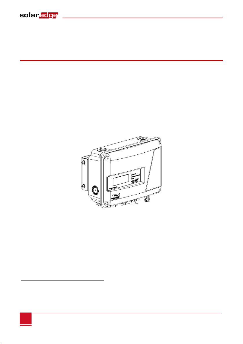
Overview
When connecting SolarEdge power optimizers to a non-SolarEdge inverter, the SolarEdge Safety and
Monitoring Interface (SMI) device enables the following features:
Safety functions of the optimizers.
Communication of the module-level data sent from the optimizers to the SolarEdge monitoring
portal.
The SMI is installed between the SolarEdge power optimizers and a non-SolarEdge inverter. The SMI is
compatible with any on-grid inverter. For some inverters, it may also serve as the inverter data logger,
which monitors power optimizers and inverter data in a single location –the SolarEdge monitoring portal
*
.
The SMI supports the optimizer SafeDC™ feature. The SafeDC™ mechanism automatically shuts down
module voltage whenever the grid power is shut down, thus providing greater safety during installation,
maintenance and firefighting.
Figure 1: The SolarEdge Safety and Monitoring Interface (SMI)
*
For a complete list of compatible inverters that can be interfaced to the SMI, refer to
http://www.solaredge.com/articles/se-smi-compatible-inverters.
Chapter 1: Introduction to the SolarEdge Safety and Monitoring Interface
Safety and Monitoring Interface Installation Manual –MAN-01-00067-2.1
7
7
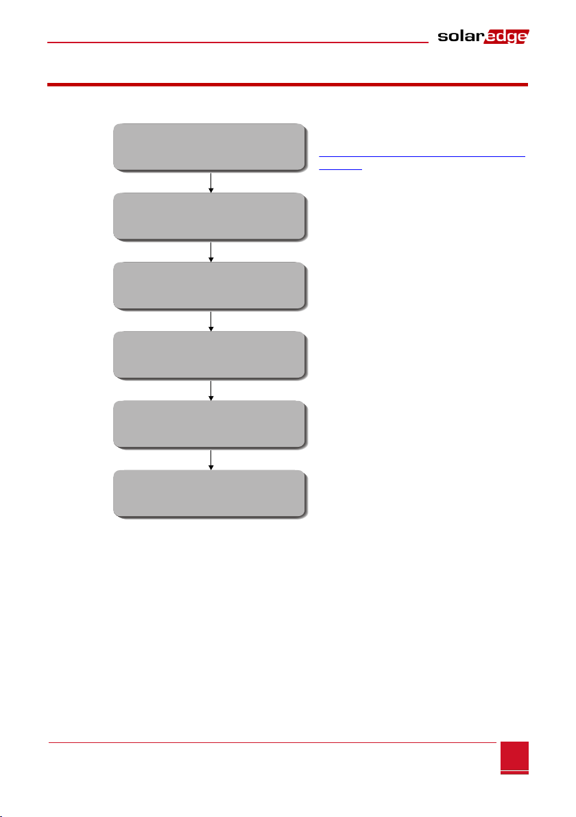
Installation Workflow
The following provides an overview of the workflow for installing and setting up a new site. Most of these
procedures can also be used for adding components to an existing site.
Refer to the SolarEdge Installation Guide
http://www.solaredge.com/groups/support/d
ownloads
Page 9
Page 13
Page 16
As described in its manual
Page 33
Step 1
Step 2
Step 3
Step 4
Step 5
Step 6
Connecting power optimizers to modules
and to a string
Connecting the Non-SolarEdge Inverter
Connecting the power optimizers or strings
to the SMI
Commissioning the SMI
(Pairing)
Connecting the SMI to the
SolarEdge Monitoring Server (Optional)
Mounting the SMI and
connecting it to AC

Chapter 1: Introduction to the SolarEdge Safety and Monitoring Interface
Safety and Monitoring Interface Installation Manual –MAN-01-00067-2.1
8
Installation Equipment List
Standard tools can be used during the installation of the SolarEdge system. The following is a
recommendation of the equipment to be used:
Allen screwdriver
Standard flat head screwdriver
Flat Head screwdriver for P25 screws (watchmaker's screwdriver)
Screwdriver for ¾" metal lock nut
Electrical screwdriver (tester)
Drilling machine and bits suitable for the surface on which the SMI will be installed
Suitable screws for attaching the mounting bracket to the surface to which it will be connected
Wire cutters
Wire strippers
Voltmeter
DC current clamp-on meter
Three-wire 4mm2 (12AWG) max AC cable with a diameter of 10–14 mm (0.4"–0.55")
For installing the communication options, you may also need the following:
For Ethernet: CAT5/6 twisted pair Ethernet cable
For RS485: Four- or six-wire twisted pair
Chapter 2: Installing the Safety and Monitoring Interface
Safety and Monitoring Interface Installation Manual –MAN-01-00067-2.1
9
9
Chapter 2: Installing the Safety and
Monitoring Interface
This chapter describes how to mount the SMI device using its mounting bracket. At this stage, power
optimizers are already installed and connected in strings. For more information on power optimizers'
installation, refer to the manuals available on the SolarEdge website at
http://www.solaredge.com/groups/support/downloads.
SMI Transport and Storage
Transport the SMI device in its original packaging, facing up and without exposing it to unnecessary
shocks. If the original package is no longer available, use a similar box, which can withstand the SMI weight
(3 kg) and can be closed fully.
Store the SMI in a dry place where ambient temperatures are -40°C to +60°C / -40°F to 140°F.
SMI Package Contents
One SMI device
One mounting bracket
Four flat head screws and eight washers for fastening the SMI to the mounting bracket
One AC cable connector with a sealing/assembly cap
One universal unlocking tool for PV module connectors
This Installation Guide
Identifying the SMI
Refer to the sticker on the SMI that specifies its Serial Number and its Electrical Ratings. Provide the serial
number when contacting SolarEdge support. The serial number is also required when opening a new site
in the SolarEdge monitoring portal.
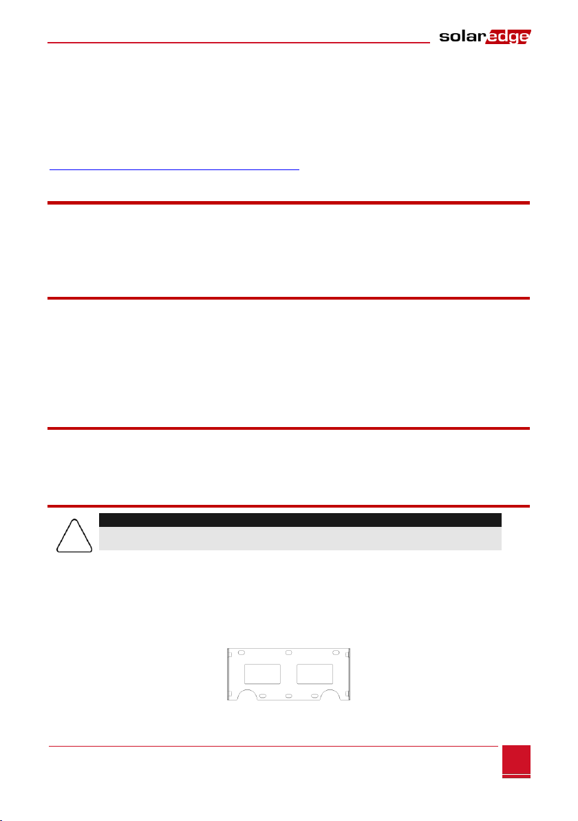
Mounting the SMI
1Determine the SMI mounting location, on a wall or pole, as follows:
To allow for heat dissipation, maintain an 8” (20 cm) clearance between the top of the IMS and
other objects.
Position the mounting bracket against a wall or pole and mark the drilling hole locations:
Ensure that the semi-circles are facing down, as shown below.
Figure 2: SMI Mounting Bracket
CAUTION:
Do not rest the connectors at the bottom of the SMI on the ground, as it may damage them.
To rest the SMI on the ground, lay it on its back, front or side.

Chapter 2: Installing the Safety and Monitoring Interface
Safety and Monitoring Interface Installation Manual –MAN-01-00067-2.1
10
Use at least two bracket holes. Additional holes can be used to fix the bracket. Determine
which and how many holes to use according to mounting surface type and material.
2Drill the holes and connect the bracket. Verify that the bracket is firmly attached to the mounting
surface.
3Attach the SMI to the bracket using the four supplied screws. Tighten the screws with a torque of
9 N*m / 6.6 lb*ft.
Figure 3: Attaching the SMI to its Mounting Bracket
SMI Connectors
The following describes the SolarEdge SMI connectors, ON/OFF switch and LCD light button:
Figure 4: SolarEdge SMI Connectors
ON/OFF Switch: Turning this switch ON (1) starts the operation of the power optimizers. Turning it
OFF (0), reduces the power optimizer voltage to a low safety voltage.
LCD Light Button: Pressing this button lights up the LCD for 30 seconds. In addition, you can press
this button to access configuration menu options, as described in Configuring the SMI Using the LCD
Light Button on page 19.
Two Communication Glands, each 20mm in diameter, for connection of inverter communication
options. Each gland has three openings. Refer to Chapter 7: Setting Up Communication on page 33.
AC Connector: Used to wire AC to the SMI
DC Inputs: Used to connect the modules strings to the SMI
DC Outputs: Used to connect the SMI to the inverter
Communication Gland 1
DC-Output
DC-Input
DC+Input
LCD Light Button
AC Connection
Communication Gland 2
ON/OFF Switch
DC+Output
Mounting Screws

Chapter 2: Installing the Safety and Monitoring Interface
Safety and Monitoring Interface Installation Manual –MAN-01-00067-2.1
11
11
Connecting the SMI to AC
The AC is connected using a special IP68-rated connector supplied with the SMI.
Use any three-wire 4mm2 (12 AWG) max AC cable with a diameter of 10–14 mm (0.4–0.55").
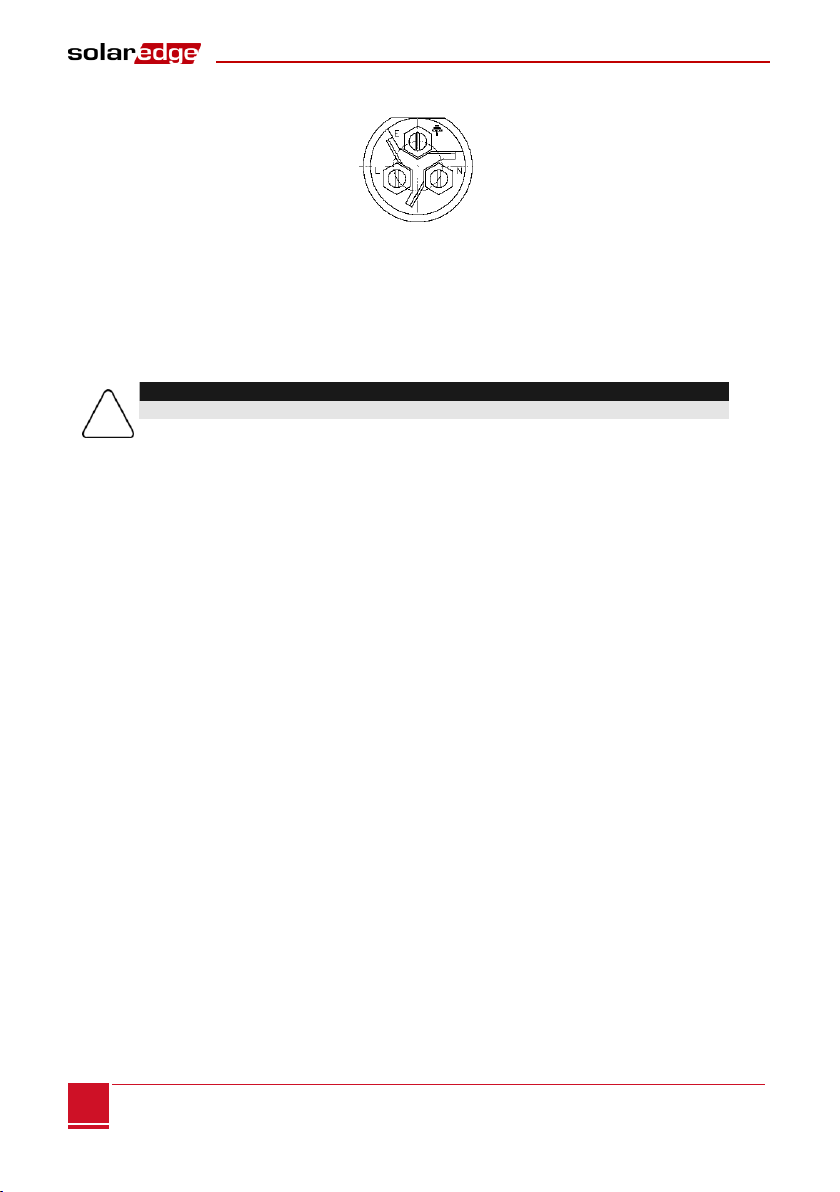
►To wire the AC connector:
1Use the sealing cap to unscrew the locking ring of the AC connector and remove the socket insert.
Figure 5: AC Connector and Sealing Cap
2Strip off the AC cable insulation and expose three wires (two line wires and one grounding wire).
3Thread the cable through the connector parts, as shown below.
Figure 6: Wiring the AC Connector
4Insert the wire ends into the terminals on the socket insert. Make sure to wire according to the local
regulations.
Gland Nut
Main Body
Socket Insert
Gland Cage
Locking Ring
Locking Ring
Sealing Cap
Chapter 2: Installing the Safety and Monitoring Interface
Safety and Monitoring Interface Installation Manual –MAN-01-00067-2.1
12
5Tighten the screws.
Figure 7: AC Connector Screws
6Pull the cable back until the socket insert is correctly positioned in the D-shaped opening of the main
body.
7Screw the locking ring into place.
►To connect the SMI to AC:
1Turn OFF the AC circuit breaker (if applicable) connected to the SMI.
2Turn OFF the ON/OFF switch at the bottom of the SMI.
3Connect the cable to the SMI AC connector and close tightly
4Turn ON the AC circuit breaker connected to the SMI.
CAUTION:
The AC circuit breaker rating should not exceed 16A.
Chapter 3: Connecting PV Strings to the Safety and Monitoring Interface
Safety and Monitoring Interface Installation Manual –MAN-01-00067-2.1
13
13
Chapter 3: Connecting PV Strings to the
Safety and Monitoring Interface
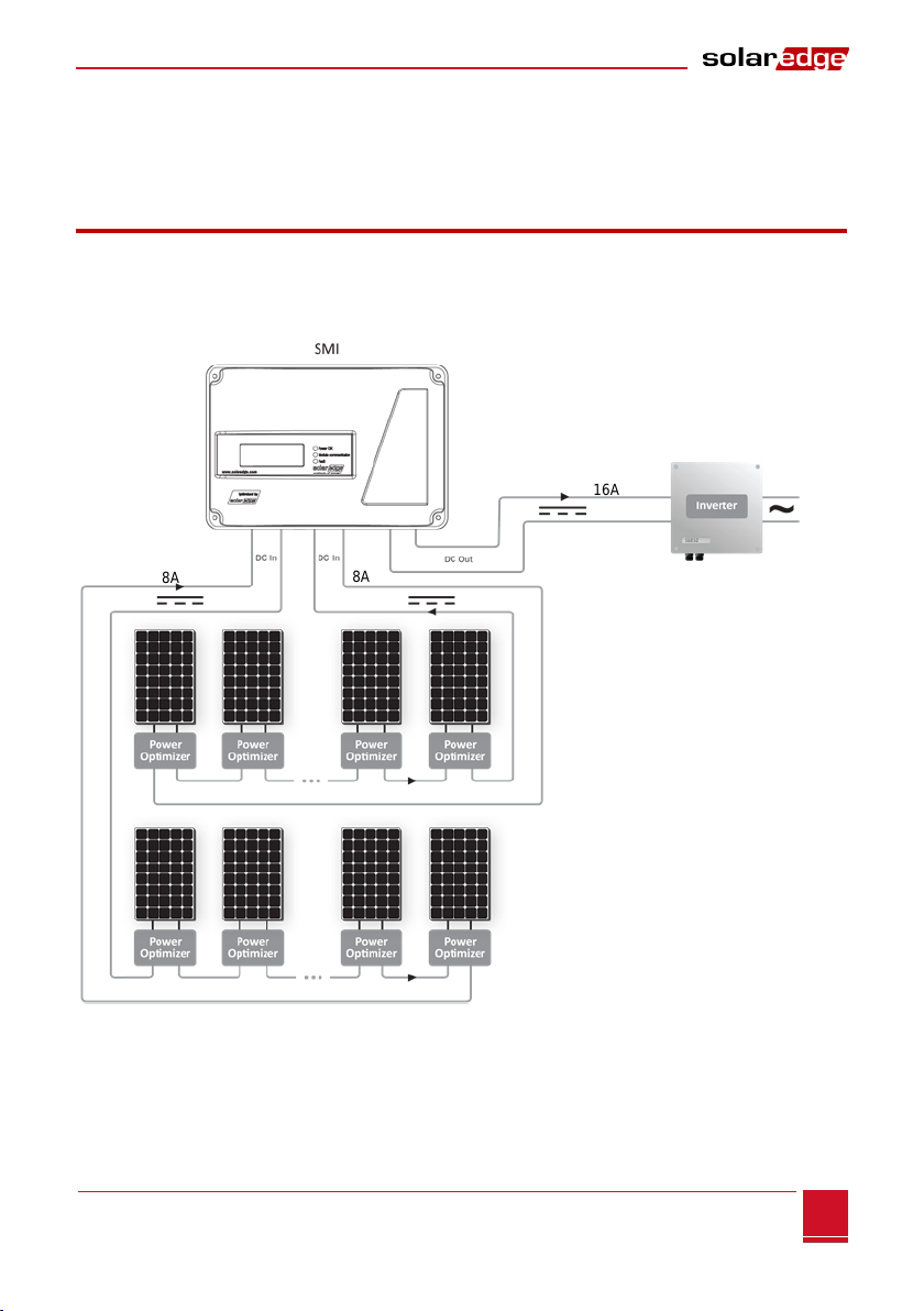
Overview
The following procedure describes how to connect the DC cables from the power optimizer strings to
the SMI.
The following example shows a connection of two strings to the SMI.
Figure 8:Example - 2 x Strings Connection, Ungrounded Array
8A
8A
16A
Non-SolarEdge
inverter

Chapter 3: Connecting PV Strings to the Safety and Monitoring Interface
Safety and Monitoring Interface Installation Manual –MAN-01-00067-2.1
14
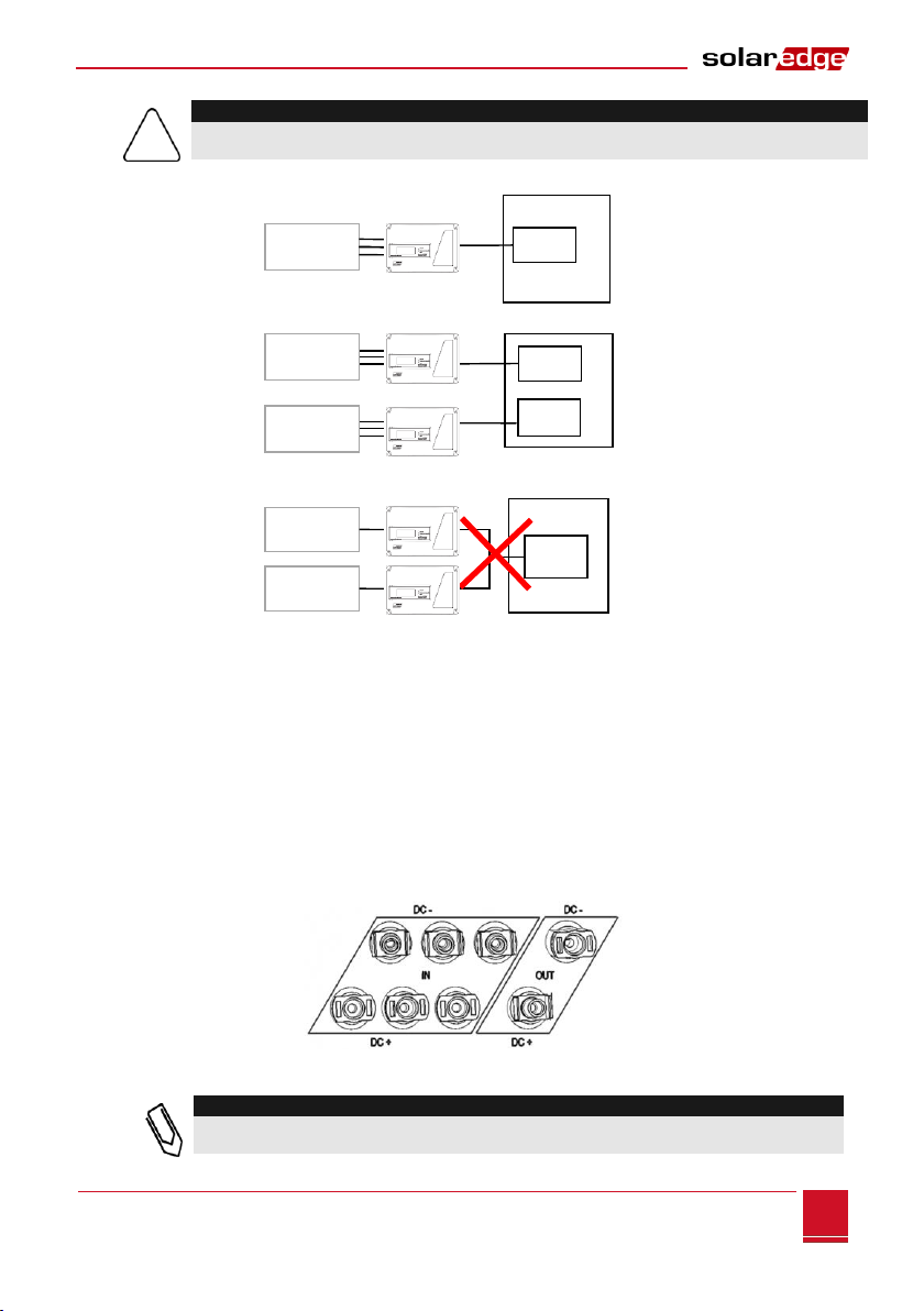
The following example demonstrates a connection of four strings to the SMI through a fused combiner
box, with proper and improper grounding locations (marked and ×).
NOTE:
When connecting the SMI to a grounded array, the grounding must not be between the SMI and
optimizers. All grounding should be at the inverter or between the SMI output and the inverter. The
SMI allows either positive or negative grounding.
Figure 9: Example - Grounded Inverter, 4 x Strings Connection, Fused (Optional) Combiner Box
Do not ground here
If grounding is
required - Ground
here, at the input of
the inverter
Non-SolarEdge
inverter
Chapter 3: Connecting PV Strings to the Safety and Monitoring Interface
Safety and Monitoring Interface Installation Manual –MAN-01-00067-2.1
15
15
CAUTION:
Only one SMI may be installed for each inverter. If the inverter has multiple MPP trackers, one SMI
may be installed for each MPPT input.
Figure 10: SMI-Inverter Connections
►To determine how many strings can be connected to the SMI:
Verify that the cumulative short circuit current (Isc) of all parallel-connected strings is below:
The rated maximum input current of the inverter
The rated maximum input current of the SMI
►To connect DC strings to the SMI:
Connect the DC strings from the photovoltaic strings of optimizers to the DC+ and DC-input
connectors as indicated. The DC inputs are wired together inside the SMI.
The SMI has three DC inputs. You can connect more than three strings to the SMI using an external
combiner box or branch cables.
Figure 11: DC Input and Output Connectors
NOTE:
For proper operation, make sure that no string diodes are connected in series between the
strings and the SMI.
Inverter
PV Strings
MPPT
MPPT
MPPT
MPPT
Inverter
PV Strings
PV Strings
Inverter
PV Strings
PV Strings
Chapter 4: SMI User Interface
Safety and Monitoring Interface Installation Manual –MAN-01-00067-2.1
16
Chapter 4: SMI User Interface
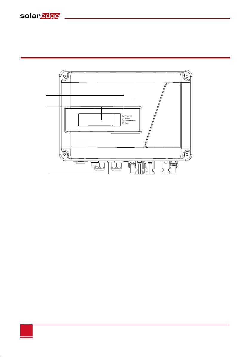
External Interface - LCD, LEDs and LCD Light Button
The front of the SMI has an LCD panel and three LEDs, as shown below:
Figure 12: SMI –LCD Panel and LEDs
The LCD panel has three LED indicators:
Power OK - Green: Indicates whether the SMI is connected to AC power.
Module Communication - Yellow: This LED blinks when monitoring information is received from a
power optimizer.
Fault - Red: Indicates that there is an error. Refer to Appendix A: Errors and Troubleshooting on page
46 for more information. In addition, this LED blinks while the SMI is being shut down.
All LEDs are on while the SMI is being configured.
The LCD Light Button is located at the bottom panel of the SMI. Pressing this button lights up the LCD for
30 seconds. In addition, you can press this button to access configuration menu options, as described in
Configuring the SMI Using the LCD Light Button on page 19.
LCD
LEDs
LCD Light
Button

Chapter 4: SMI User Interface
Safety and Monitoring Interface Installation Manual –MAN-01-00067-2.1
17
17
Internal Interface - The LCD User Buttons
Four buttons are located at the top of the LCD panel inside the SMI and are used for controlling the LCD
menus, as shown below:
Figure 13: LCD Internal Menu Buttons
Esc: Moves the cursor to the beginning of the currently displayed parameter; goes to the previous
menu, and cancels a value change with a long press (until Aborted is displayed).
Up (1), Down (2): Moves the cursor from one menu option to another, moves among the characters
of a displayed parameter, and toggles between possible characters when setting a value.
Enter (3): Selects a menu option and accepts a value change with a long press (until Applied is
displayed).
Use the three rightmost buttons for entering 123 when entering the password.
The LCD panel and buttons may be used during the following:
Setup: After inverter installation, the field technician may perform basic inverter configuration, as
described in Configuring the SMI Using the LCD User Buttons on page 18.
Operational Mode: The LCD panel enables checking that the inverter is working properly. Refer to
Operational Mode –Status Screens on page 24 for a description of this option. Use the LCD light
button to toggle through the informative displays.
Error messages: In the event of a problem, an error message may be displayed on the LCD panel.
Refer to Appendix A: Errors and Troubleshooting on page 46 and to Configuring the SMI Using the
LCD User Buttons on page 18 for more information.
Esc
Up (1)
Down (2)
Enter (3)

Chapter 4: SMI User Interface
Safety and Monitoring Interface Installation Manual –MAN-01-00067-2.1
18
Setup
The SMI can be configured in one of two ways:
Configuring the SMI Using the LCD User Buttons, page 18. When using this option, the SMI cover is
removed.
Configuring the SMI Using the LCD Light Button, page 19. When using this option, removing the SMI
cover is not required.
Configuring the SMI Using the LCD User Buttons
1Turn OFF the DC from the inverter, either by turning off the DC breaker (if applicable) or by turning
OFF the inverter as described in its manual.
2Turn the SMI ON/OFF switch to OFF.
WARNING!
If the SMI was operating properly (power was produced by the power optimizers),
the following message is displayed.
D C V O L T A G E N O T
SAFE
D O N O T
DISCONNECT
V D C :
72.0
This message is displayed until the DC voltage is safe (50V). Do not open the cover
until the voltage is safe or until at least five minutes have passed.
WARNING!
Do not touch the DC power connections until the DC voltage is at a safe level. Doing
so may cause injury or loss of life, damage to the device and/or danger of fire.
3Open the SMI cover, as described in Appendix D: Opening and Closing the SMI Cover on page 51.
4Press the Enter button for at least 5 seconds. The following message is displayed:
P l e a s e ente r
P a s s w o r d
* * * * * * * *
5Use the three rightmost internal LCD user buttons to type in the following password: 12312312. The
following message is displayed:
L a n g u a g e < e n g >
Communication
Display
Maintenance
Information
The SMI is now in Setup mode and all its LEDs are lit. The SMI automatically exits Setup mode if no
buttons are pressed for more than 2 minutes.
Chapter 4: SMI User Interface
Safety and Monitoring Interface Installation Manual –MAN-01-00067-2.1
19
19
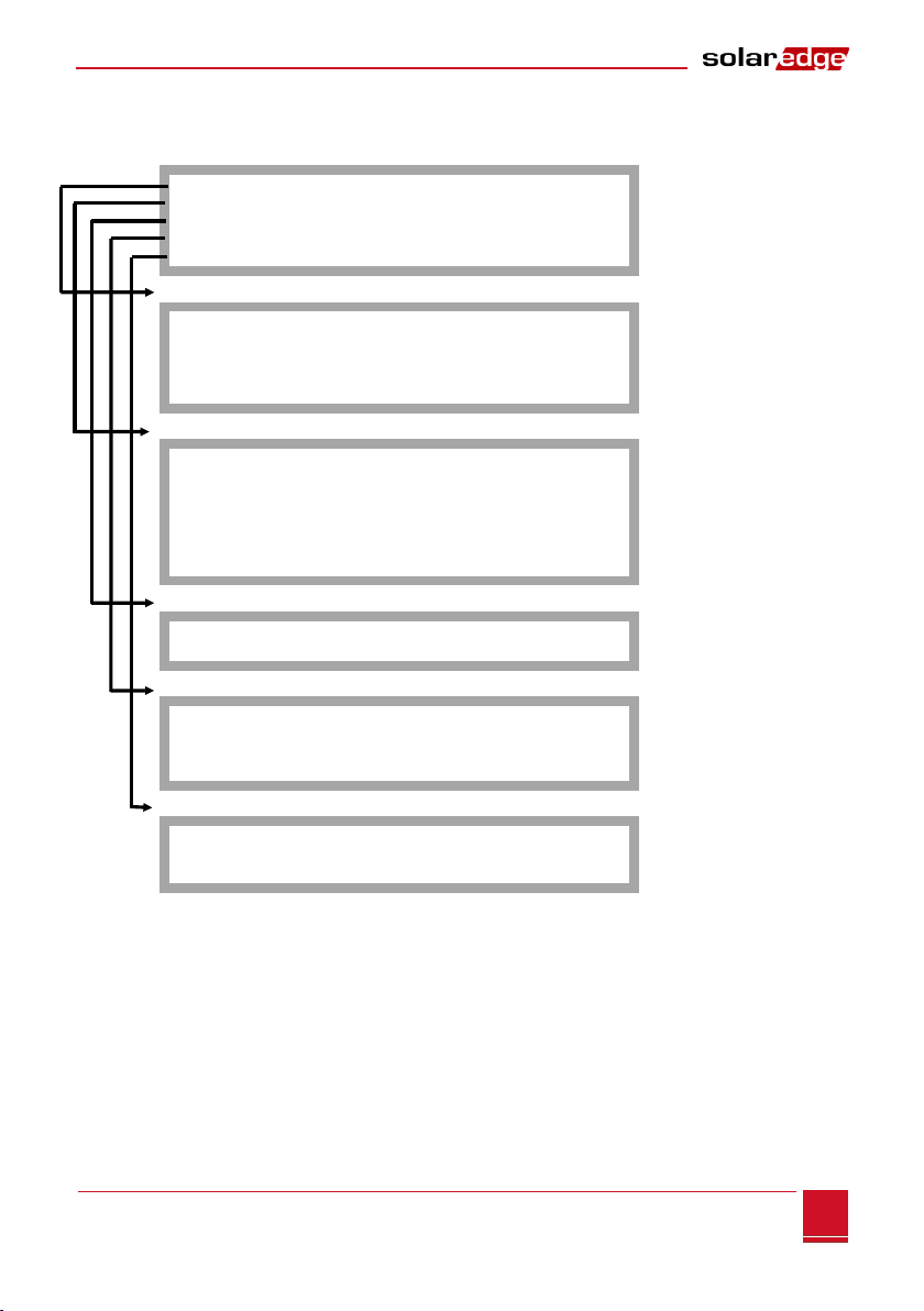
The following shows a hierarchical tree of the menu options, which are described in SMI
Configuration Menu Options on page 21
L a n g u a g e < e n g >
Communication
Display
Maintenance
Information
Language:
English
German
Spanish
French
Italian
Communication:
Server<LAN>
L A N C o n f
RS485–1 C o n f < M >
RS485–2 C o n f < S >
ZigBee Conf<S>
R S 2 3 2 C o n f
S l a v e D e t e c t
Display:
L C D O n T i m e < 3 0 >
T L M O n T i m e < 1 5 >
Maintenance:
D a t e a n d T i m e
R e s e t C o u n t e r s
Factory Reset
S W U p g r a d e S D - Card
Information:
Versions
E r r o r L o g
W a r n i n g l o g
Each menu option is described in SMI Configuration Menu Options on page 21.
Configuring the SMI Using the LCD Light Button
The LCD light button can be used for communication setup and displaying the Error log and Warning Log
without having to open the SMI cover. There are fewer menus available when using this configuration
option; however, the functionality is the same as when using the LCD User buttons.
1Press and hold down the LCD light button until the following message is displayed:
Table of contents
Other SolarEdge Recording Equipment manuals


