Soundavo PSA-1250V User manual
OWNERS MANUAL
PSA-1250VCOMMERCIAL
MULTI-ZONE AMPLIFIER

WARNING
1. Do not place or install this device in an area where it can be exposed to excessive amounts of
dust, humidity, oil,smoke, or combustible vapors.
2. To prevent risk of electrical shock or fire hazard, due to overheating do not obstruct unit’s
ventilation openings.
3. Do not install near any source of heat, including other units that may produce heat.
4. Do not expose this device to excessively high temperatures. Do not place it in, on, or near heat
sources, such as a fireplace, stove, radiator, etc. Do not leave it in direct sunlight
5. Do not touch the device, the power cord, or any other connected cables with wet hands.
6. This device ventilates excessive heat through the slots and openings in the case. Do not block
or cover these openings. Ensure that the device is in an open area where it can get sucient
airflow to keep from overheating.
7. Only clean unit with a dry cloth.
8. Unplug unit during lightning storms or when not used for an extended period of time.
9. Protect the power cord from being walked on or pinched, particularly at the plugs.
10. Use unit only with accessories specified by the manufacturer.
11. Refer all servicing to qualified personnel.
2
Thank you for purchased Soundavo product. Please read this
entire manual before using this device, paying extra attention to
these safety warnings and guidelines. Please keep this manual in
a safe place for future reference.

FRONT PANEL
The PSA-1250V is a 6 Zones (12 Channels) audio distribution amp that can be confgured for six stereo 4
Ohm/8 Ohm zones (30W/channel @ 8 Ohms; 60W/channel @ 4 Ohms); but it can also be configured
for six stereo 70/100V zones (120W/per Zone); or three high powered bridged zones(120W @ 8
Ohms). It also can be configured for any combination of stereo 4 Ohms/8 Ohms, 8 Ohms bridged and
70/100V zones all at the same time. Which is a versatile multi-channel amplifier provide the good
solution for either residential or the 70V/100V contractor/install applications, and perfect for the
distribution of multiple speaker systems over long cable runs, such as in-ceiling speakers, surface-mount
speakers and paging horns.
INTRODUCTION
1
2 3
3
THERMAL PROTECTION
PSA-1250V amplifieris designed withspecialcircuitry to safeguard theamplifier underathermal
overload condition. Thermalprotectionmode willonly engage when theunithasbeen runat high
volume for extended periods of timewithoutadequate ventilationand/or when speaker impedances
are below the minimum levels for the amplifier. In thermalprotection modetheamplifier will
automaticallystop output. If this fault occurs,turn o the amplifier, andcheck thatthespeaker
impedance ratingis abovethe minimumrating. Alsocheck for adequate ventilationaroundthe
amplifierandmake adjustments if necessary. Once the unit has cooledto sageoperating
temperatures,the amplifier may be powered back on.Special circuitry has been designed into the
amplifier to safeguard under a short-circuit condition. Afaulty speaker can also cause a short circuit
condition.
INSTALLATION
The amplifier canbe placed on ashelfin an equipment rack, or on atableor cabinet.Be sure the
required clearances for ventilationand heatdissipation.The amplifierwilltake two rackspaces
withthefeet removed.
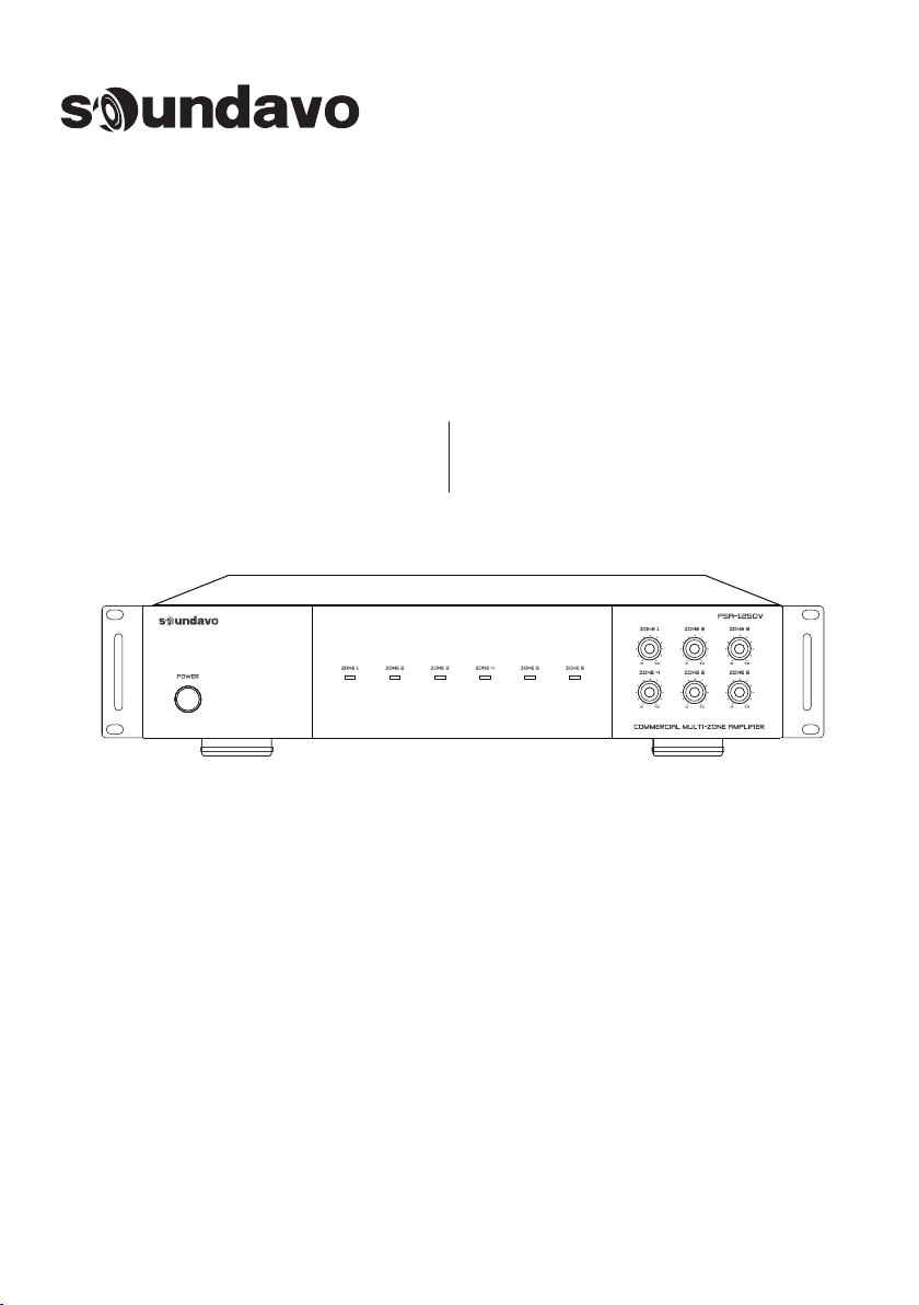
Volume controls for each zone (Stereo Left/Right channels
or Bridge Mono mode) adjust the sound level
independently (Counterclockwise for minimum; clockwise
for maximum.) This allows the output level of each speaker
to be perfectly matched to its area. It can also be used to
limit the maximum audio level in a certain area.
3. Gain Controls:1. Power Switch:
This switch turns the AC mains On or OFF
2. Zone LED:
Blue: the corresponding zone is powered on
OFF: the corresponding zone is o (standby mode).

REAR PANEL
4. Audio Bus Input/Output: The PSA-1250V amplifier
has a BUS input that receives audio signals from
standard balanced audio sources via plug-in screw
terminal connector that can be used to connect a single
source to multiple zones switched to BUS using the
Line/Bus Switch. The BUS output are passive pass
through the corresponding of the BUS Input and can
be used to daisy chain the source to other amplifiers in
the system.
5. Local Line Input RCA Connector: Local input for
zone (plays only on that specific zone’s outputs). Use
for instances where the zone will always play a dierent
source than other zones. Set the Zone Input Selector
switch to “Line In” to use this input.
6. 4Ω/8ΩZone Speaker Output Terminal:
Stereo 4Ω/8ΩMode - Use indicated terminals for
normal stereo speaker connections. (2 x 30W @ 8
Ohms; 2 x 60W @ 4 Ohms)
NOTE 1: 4Ω/8Ω- 70V/100V switch must be in the "4
Ω/8Ω" position
NOTE 2: The Stereo/Bridged switch must be in the
OUT (Stereo) position.
Bridge 8ΩMode - Use indicated terminals for high
output mono speaker connection. (1 x 120W @ 8
Ohms)
NOTE 1: 8Ω/4Ω- 70V/100V switch must be in the "4
Ω/8Ω" position.
NOTE 2: The Stereo/Bridged switch must be in the IN
(Bridged) position.
4
7. Hi-Z Zone Speaker Output Terminal:
70V/100V Mode - Use indicated terminals for
70V/100V stereo speaker connections. (120W @
70V/100V)
NOTE 1: 8Ω/4Ω- 70V/100V switch must be in the
“70V/100V" position.
NOTE 2: 70V/100V High Voltage Speaker Output
Switch must be set to proper voltage.
NOTE 3: The Stereo/Bridged switch must be in the
OUT (Bridged) position.
8. Line/Bus Switch: Each Zone's input source can be
selected using this switch. Depress the button to select
the audio programcoming from the BUS Input or leave
it in the up position to use the Zone's Line Input.
9. 4Ω/8Ω& 70V/100V Switch: Select the zone
speaker output between 4Ω/8Ωand 70V/100V
10. Line Input Mode Switch: Select whether a pair of
left and right output channels are individual or bridged
together for a more powerful mono channel, the
Bridge Output mode is ideal for powering larger
speakers or speakers on long cable runs.
Stereo: For stereo signals, leave switch in the OUT
(Stereo) position. This applies to all connections in the
4 ohm / 8 ohm configuration.
Bridge: ONLY press this button when using the
"Bridged 8 Ohm" or "70/100V mode" speaker wiring
connection in a giving zone.
CAUTION: In Bridge mode, an amplifier encounters a
load that is about one half of its actual value a 4-ohm
load would therefore be 2-ohms to a bridged amp and
if the amplifier isn't designed to run Safely into such a
low impedance (which the PSA-1250V is not) damage
may occur tothe amplifier. We do not recommend
connecting a 70V Speaker circuit while in Bridge
mode as the output will be at 140V and the sound can
be distorted.
11. Zone Audio Limiter: Press to activates a -20dB
input limiter, for the specific zone, to help reduce the
level of accidental audio peaks and clipping distortion
by zone. Leave in the OUT position to pass audio
through unprocessed. Press IN to actiate the input
limiter.
12. Voltage Switch: The unit is set at the factory for 115V
U.S. operation; simply connect the included IEC power
cord to your wall outlet. For 230V operation, move the
voltage selector switch to the 230V position. When
operating at 230V the internal fuse located in the IEC
socket should also be changed. In most 230V
applications a separate power cord will be required and
is not included.
13. AC Input: Apply the correct voltage before operate
the amplifier, use the supplied 3-pin ground power
cable to connect the unit.
FUSE - For 110V-120V/60Hz use a T10.0AL/250V fuse.
For 220V-240V/50Hz use a T5.0AL/250V fuse.
6
13
7 9
1210 114 85

4. Audio Bus Input/Output: The PSA-1250V amplifier
has a BUS input that receives audio signals from
standard balanced audio sources via plug-in screw
terminal connector that can be used to connect a single
source to multiple zones switched to BUS using the
Line/Bus Switch. The BUS output are passive pass
through the corresponding of the BUS Input and can
be used to daisy chain the source to other amplifiers in
the system.
5. Local Line Input RCA Connector: Local input for
zone (plays only on that specific zone’s outputs). Use
for instances where the zone will always play a dierent
source than other zones. Set the Zone Input Selector
switch to “Line In” to use this input.
6. 4Ω/8ΩZone Speaker Output Terminal:
Stereo 4Ω/8ΩMode - Use indicated terminals for
normal stereo speaker connections. (2 x 30W @ 8
Ohms; 2 x 60W @ 4 Ohms)
NOTE 1: 4Ω/8Ω- 70V/100V switch must be in the "4
Ω/8Ω" position
NOTE 2: The Stereo/Bridged switch must be in the
OUT (Stereo) position.
Bridge 8ΩMode - Use indicated terminals for high
output mono speaker connection. (1 x 120W @ 8
Ohms)
NOTE 1: 8Ω/4Ω- 70V/100V switch must be in the "4
Ω/8Ω" position.
NOTE 2: The Stereo/Bridged switch must be in the IN
(Bridged) position.
SPECIFICATIONS
FEATURES:
• Each zone can independently select a zone-specific
stereo audio source or the global mono Audio Bus input
(balanced)
• Each zone can be independently configured for stereo 4
Ohm/8 Ohm mode, high powered bridged 8 Ohm
mode, or 70V/100V mode for total flexibility within a
given installation
• Stereo Mode (4 Ohm) per Zone: 2 x 60W THD 0.8%
• Stereo Mode (8 Ohm) per Zone: 2 x 30W THD 0.8%
• Bridged Mono Mode (8 ohms) per Zone: 120W W THD 0.8%
• 70/100V Mode per Zone: 120W
• Total Harmonic Distortion: 1%
• Signal-to-Noise Ratio: -95dB
• Channel Separation: -60 dB
• Frequency Response: 20Hz---20KHz 1.5dB
• Input Sensitivity: 380mV
• Line Input Impedance: 47K
• Dimensions: 16.81”W x 3.46” H x 16.14”D (42.7 x 8.8 x 41.0 cm)
• Weight: 43 lbs (19.25 kg)
5
7. Hi-Z Zone Speaker Output Terminal:
70V/100V Mode - Use indicated terminals for
70V/100V stereo speaker connections. (120W @
70V/100V)
NOTE 1: 8Ω/4Ω- 70V/100V switch must be in the
“70V/100V" position.
NOTE 2: 70V/100V High Voltage Speaker Output
Switch must be set to proper voltage.
NOTE 3: The Stereo/Bridged switch must be in the
OUT (Bridged) position.
8. Line/Bus Switch: Each Zone's input source can be
selected using this switch. Depress the button to select
the audio programcoming from the BUS Input or leave
it in the up position to use the Zone's Line Input.
9. 4Ω/8Ω& 70V/100V Switch: Select the zone
speaker output between 4Ω/8Ωand 70V/100V
10. Line Input Mode Switch: Select whether a pair of
left and right output channels are individual or bridged
together for a more powerful mono channel, the
Bridge Output mode is ideal for powering larger
speakers or speakers on long cable runs.
Stereo: For stereo signals, leave switch in the OUT
(Stereo) position. This applies to all connections in the
4 ohm / 8 ohm configuration.
Bridge: ONLY press this button when using the
"Bridged 8 Ohm" or "70/100V mode" speaker wiring
connection in a giving zone.
CAUTION: In Bridge mode, an amplifier encounters a
load that is about one half of its actual value a 4-ohm
load would therefore be 2-ohms to a bridged amp and
if the amplifier isn't designed to run Safely into such a
low impedance (which the PSA-1250V is not) damage
may occur tothe amplifier. We do not recommend
connecting a 70V Speaker circuit while in Bridge
mode as the output will be at 140V and the sound can
be distorted.
11. Zone Audio Limiter: Press to activates a -20dB
input limiter, for the specific zone, to help reduce the
level of accidental audio peaks and clipping distortion
by zone. Leave in the OUT position to pass audio
through unprocessed. Press IN to actiate the input
limiter.
12. Voltage Switch: The unit is set at the factory for 115V
U.S. operation; simply connect the included IEC power
cord to your wall outlet. For 230V operation, move the
voltage selector switch to the 230V position. When
operating at 230V the internal fuse located in the IEC
socket should also be changed. In most 230V
applications a separate power cord will be required and
is not included.
13. AC Input: Apply the correct voltage before operate
the amplifier, use the supplied 3-pin ground power
cable to connect the unit.
FUSE - For 110V-120V/60Hz use a T10.0AL/250V fuse.
For 220V-240V/50Hz use a T5.0AL/250V fuse.
• Each zone has -20dB Audio Limiter
• Front panel features “Zone ON” and “Zone Standby”
LED indicators for each zone
• Rack mountable in standard 19" rack (2U height)
• Selectable 110/220 AC voltage

INSTALLATION
4. If the cabinet contains other heat generating components or several PSA-1250V’s are
being used, be sure to provide adequate ventilation to dissipate heat the units can
generate.
2. The PSA-1250V is designed for mounting into standard 19" (483mm) racks or on fat
horizontal surfaces.
3. If mounted in an equipment cabinet or other confining location, allow at least 2 inches of
space above the top cover. Be sure there are large openings in the shelf below the unit and
in the cabinet to allow the entry of cool air and the escape of warm air.
1. The PSA-1250V is convection cooled. It depends on the natural free fow of air up
through the slot perforations in the bottom plate, over the internal heat dissipating fins, then
out the top cover, for adequate cooling.
7. Be sure to leave adequate space for large bundles of wire and dress them in such a
manner that does not block airflow. Leave enough ‘play’ in the wires for making connections
should the system require service.
6. When installing the PSA-1250V in a rack, please use racks that feature a rear support
provision. Adding a single RU (Rack Unit) vent above and below the PSA-1250V will
improve convection in heavy use applications. [One Rack Unit size = 1-3/4" (44.5mm) in
height]. Also try to mount the amplifier(s) at the top of the rack so heat dissipation does not
affect other devices.
5. Use fans (quiet, boxer type), if necessary, to ensure a constant fow of air through the
PSA-1250V’s and the other heat generating components.
6
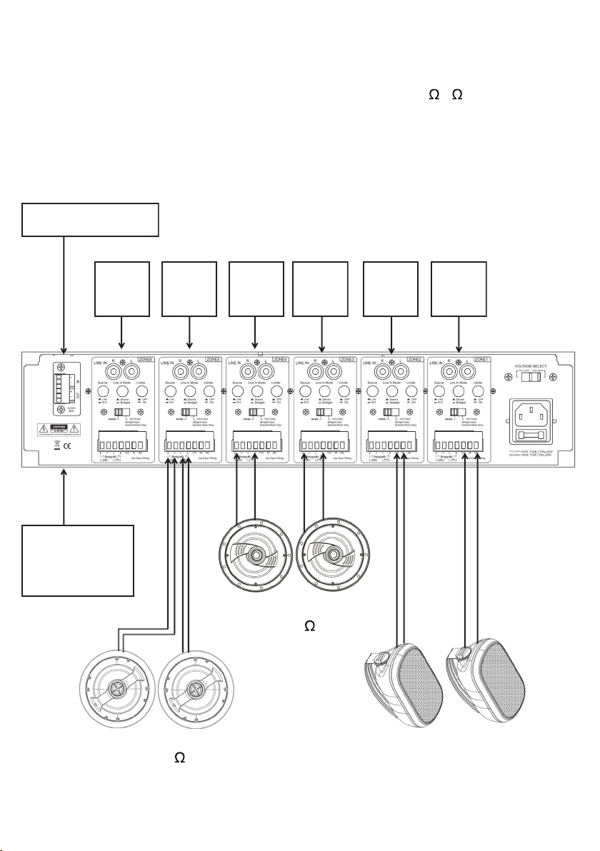
Typical System application for the PSA-1250V audio distribution amplifier. The amp
can be set for any combination of high-power bridged, normal 8 /4 or 70/100V
zones. All zones can select local or Bus sources and can be controlled via the
source select switch on the rear panel.
Stereo Zone
Stereo Bridged Zone
Medium Power 4/8 Speakers
High Power 8 Speakers
70/100V Speakers
70/100V Zone
Audio
Source
A
Audio
Source
F
Bus Audio Source
Audio
Source
D
Audio
Source
C
Audio
Source
B
Audio
Source
E
Bus Out to
other
Audio Device
TYPICAL PSA-1250V SYSTEM APPLICATION
7
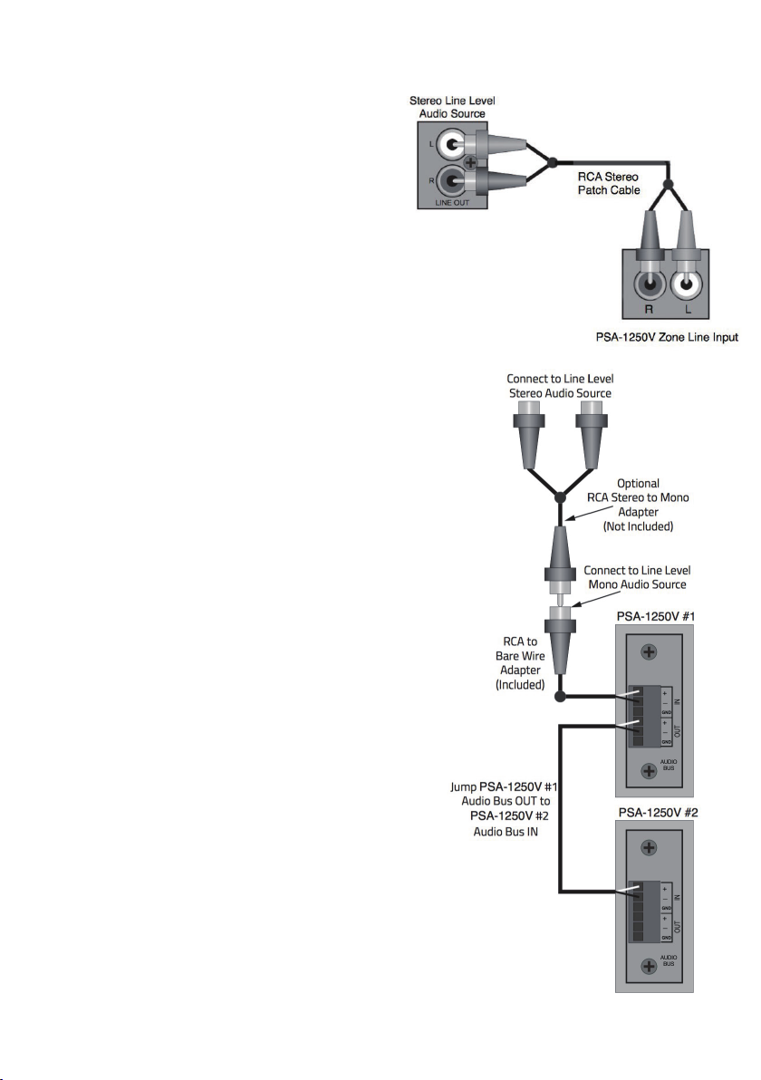
AUDIO CONNECTION
Zone Line In
This connection is an input for a dedicated zone
line-level audio source. If multiple line level audio
sources are required in a zone, use an audio
switch on the zone Line IN or use a multi-source,
multi- zone controller if multiple audio sources are
required in multiple zones.
Audio Bus In
This connection will distribute unbalanced line
level audio to any zone set to ‘Bus’ with the Line/
Bus Trigger IN.
NOTE: This is a mono unbalanced line level input.
If connecting a stereo line level device, use an
appropriate stereo to mono ‘Y’ adapter as shown
when making this connection.
1. IN - Connect the RCA to bare wire adapter to
the Audio Bus IN +/GND terminals as shown.
2. Connect the Audio Bus IN Source to the RCA
adapter. Use a stereo to mono adapter if
connecting a stereo source.
NOTE: Polarity of RCA plugs/jacks is typically pin
= signal, sleeve =GND.
Audio Bus Out
This connection will send the unbalanced line level
audio source connected to the Audio Bus IN to the
Audio Bus IN on another PSA-1250V or other audio
amplifier.
1. OUT - Using either the RCA adapter or bare
wire, connect the Audio Bus OUT +/GND
terminals on PSA-1250V #1 to the Audio Bus IN
+/GND terminals on PSA-1250V #2. Use an RCA
to bare wire adapter if connecting to a device
with line level RCA jacks.
NOTE: Polarity of RCA plugs/jacks is typically pin = signal, sleeve =GND.
1. Line In: Using a quality, stereo audio RCA- RCA
patch cable with gold ends, connect the L&R line
level OUTs on the audio source to the L&R Line Ins
on the appropriate PSA-1250V zone.
8

The PSA-1250V is a fexible multi-channel amplifer capable of many different
applications. The application for a given system, or even different amp configurations for
different zones within a single system can create different requirements for speaker wire
runs. Please review the information below and apply these guidelines to your particular
application(s).
Speaker Wire
Multi-Room Audio -Stereo or Bridged (4/8 )Connection
Speaker Output Mode Selection
WIRING INFRASTRUCTURE
NEVER CHANGE THE 70V/100V HIGH VOLTAGE SPEAKER OUTPUT, 8 /4 -70V/ 100V
OR STEREO/BRIDGED SETTINGS WHILE THE AMP IS TURNED ON OR CONNECTED
TO AC POWER!!!
If the PSA-1250V amp is being used to distribute 70V/100V audio, pull distribution lines
(each distribution line is a wire pair) in a daisy-chain pattern, (amp to first speaker, first
speaker to second speaker, second speaker to third speaker, etc.) If distributing stereo, pull
two distribution lines (two pair) to each speaker location in a daisy chain from the amp
location. Use quality stranded speaker wire based upon the 70V Speaker Wire Gauge Table
below.
70V/100V Connection
The PSA-1250V has three amplifer modes for zone speaker connections. Bridged 8 Ohms,
4/8 Ohms Stereo and 70V/100V. Any mix of amplifier modes is allowable in differient
zones...as long as they are configured correctly.
If the PSA-1250V amp is being used to distribute audio from the PSA-1250V Zone Line
INs or Audio Bus IN, to different rooms with 4/8 Ohm speakers, with a multi-zone preamp/
controller then pull home-runs directly from the speaker locations or speaker terminal
plates to the amplifier location. Use quality stranded speaker wire based upon the 4/8
Speaker Wire Gauge Table below.
9
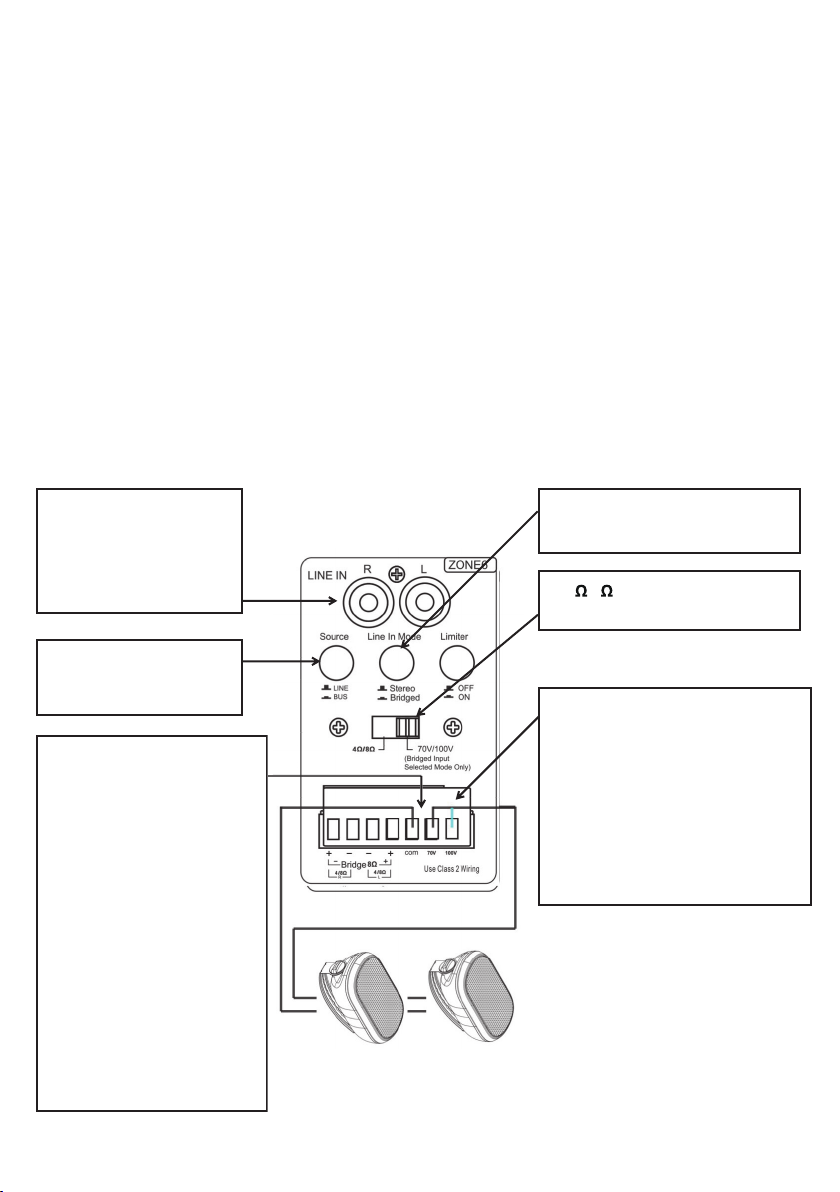
SPEAKER OUTPUT CONNECTIONS
70/100V Mode Speaker Output Application -
70V/100V speaker system are wired using a dsisy-chain configuration where the amp feeds a speaker, then
that speaker connects to the next speaker and so on.
When setting an PSA-1250V zone for 70V/ 100V, be sure to accurately calculate the total wattage required
and not exceed the PSA-1250V 70V/100V zone’s output, 30W per channel in 70V/100V mode.
Typically 70V amp power requirement can be calculated by adding the total of the tap wattage set for all
speakers to be connected to a 70V/ 100V zone and multiplying it by 1.2. This will allow roughly a 20% loss
of efficiency, typical for this type of system
1. Zone Line IN: Connect
the L & R line level OUT
on the zone audio source
to the appropriate zone
LINE IN L & R
2. Select Input Source:
Choose the Input source
betwen LINE & BUS
3. Stereo/Bridged Switch: Set to
the Bridged position.
4. 4 /8 or 70/100V Switch: Set
to the 70V/100V position.
5. Speaker Connections:
Connect the right 70V
distribution line +/- wires to the
right 70V/100V distribution line
+/- wires to the right 70V or
100V +/- terminals as shown
NOTE 1: Speaker terminals
may not be specifically marked
In/Out/
NOTE 2: In a 70/100V system
+/- polarity is not critical in
same way as in a 4/8 ohm
system. But it is critically
important that the connections
be consistent, that is, plus to
plus, minus to minus.
6. 70V/100V High Voltage Speaker
Output - wiring the speaker into the
70V connector if PSA-1250V AC
Voltage Select switch is set to
110~120VAC.
Set to 100V if PSA-1250V AC
Voltage Select switch is set to
220~240VAC. This setting will
affect all zones set to 70V/100V.
This configuration creates a stereo 70V speaker zone. (120W/zone) A70V/ 100V system utilizes speakers
with special taps that set the wattage/ volume of each speaker.
If the total wattage exceeds 120 Watts for a 70/100V zone, reducet the load to any given zone by
connecting 70V/100V speakers to multiple zones set to 70V/ 100V to safely distribute the load.
10

4 /8 Stereo Mode Speaker Output Application -
8Bridged Mode Speaker Output Application -
1. Zone Line IN: Connect
the L & R line level OUT
on the zone audio source
to the appropriate zone
LINE IN L & R
2. Select Input Source:
Choose the Input source
betwen LINE & BUS
5. Speaker Connections: Connect
the wire from the right ‘speaker
-’terminal to the right ‘4/8 -’ terminal
as shown in: Stereo 4/8 Connection.
Connect the wire from the right
‘speaker +’ terminal to the right ‘4/8
+’terminal as shown in: Stereo 4/8
Connection. Repeat for the left
channel speaker.
4. 4/8 or 70/100V Switch: Set
to the 4/8 position.
3. Stereo/Bridged Switch: Set to
the Stereo position
Bridging a zone amp creates an 120 Watt RMS mono @ 8 ohm power output
This configuration creates a standard zone stereo speaker output. (30W @ 8 Ohms/60W @ 4 Ohms)
11
Table of contents
Other Soundavo Amplifier manuals

Soundavo
Soundavo NSA-250 User manual

Soundavo
Soundavo PSA-50H User manual

Soundavo
Soundavo WS66I User manual

Soundavo
Soundavo CSA-60 User manual

Soundavo
Soundavo MZ-1650S User manual

Soundavo
Soundavo PSB-1000 DSP User manual

Soundavo
Soundavo PSA-4600 User manual

Soundavo
Soundavo PSB-300 User manual

Soundavo
Soundavo M66-EXT User manual

Soundavo
Soundavo WS66I User manual


