Soundavo WS66I User manual

WS66I
OWNERS MANUAL
6 Source / 6 Zone
Matrix Amplifier with Streamers
Audio Distribution Network Controller

2

INTRODUCTION
FEATURE
*High efficiency more than 85% Class D amplification.
*6 Line input sources, including 2 Audio Streamers (Input 3, 4).
*USB ports for playing music files from USB Flash Drive (Input 3, 4).
*Each zone Stereo/Mono output selectable.
*Enable control over Ethernet.
*Support Control APP.
*PRE-AMP output on Zone1~6.
*Built-in IR receiver & IR remote controller for Source
select/Volume/Treble/Bass.
*12V DC trigger output to external device when the system is power on.
*12V DC mute trigger input from the external devices.
*RJ45 Ethernet port for the wired connection to the local network.
*Another RJ45 Ethernet expansion port for connecting with smart TV or other
device.
*RS-232 port allows 2-way communication with the Home Automation system.
*Expandable up to 18 Zones by additional 2 units.
*6 LEDs for 6 zones Power On, Standby and Mute.
*Built in IR emitter.
*AC 115V / 230V input power switchable.
3
The WS66I matrix amplifier home audio system brings you the advanced
Generation Dtechnology, it is afunctional, easy-to-install, highly compatible,
expandable and used-friendly audio distribution system. With few simple
steps to install, it provides up to 50W x2power by class Damplifier and
distribute at most to 18 zones which all can be controlled by APP, or option
keypads &IR remote controller
Simply connecting the WS66I to the local Ethernet network, it let you access a
wide variety of music from the built-in WiFi streaming services or stored on
the smartphone. Two USB ports on the front panel for playing music files from
USB storage devices. An Optical digital input to manage the sound of aflat
screen or aCD player to have high resolution of sound quality in each zone.
The overall distribution system including package device is easy-to-install, so
every audiophile in every zone can use IR controller or keypads as option to
enjoy the powerful audio. High functionality and performance bring you
musical enjoyment just the way you want it.
*Each zone provides 50W x2(@ 4Ohm) output power.
SPECIFICATION
Output Power:
Output Power:
Output Power:
S/N:
THD:
Frequency Response:
Input Impedance:
Input Sensitivity:
Protection Function:
System on Voltage:
External Mute Voltage:
Power Supply:
Output Connection:
Input Connection:
Sampling Rate(Streamer):
Audio Format(USB):
Streamer Support:
USB type:
Network:
Dimension:
Weight:
25W x 2 per zone (at 8Ω)
50W x 2 per zone (at 4Ω)
100W per zone (Bridged at 8Ω)
>85dB A WTD
<0.1%
20Hz-20KHz
RJ45, Standard 10/100Mb
430mm x 89mm x 416 mm (WxHxD)
12KG
1 2 3
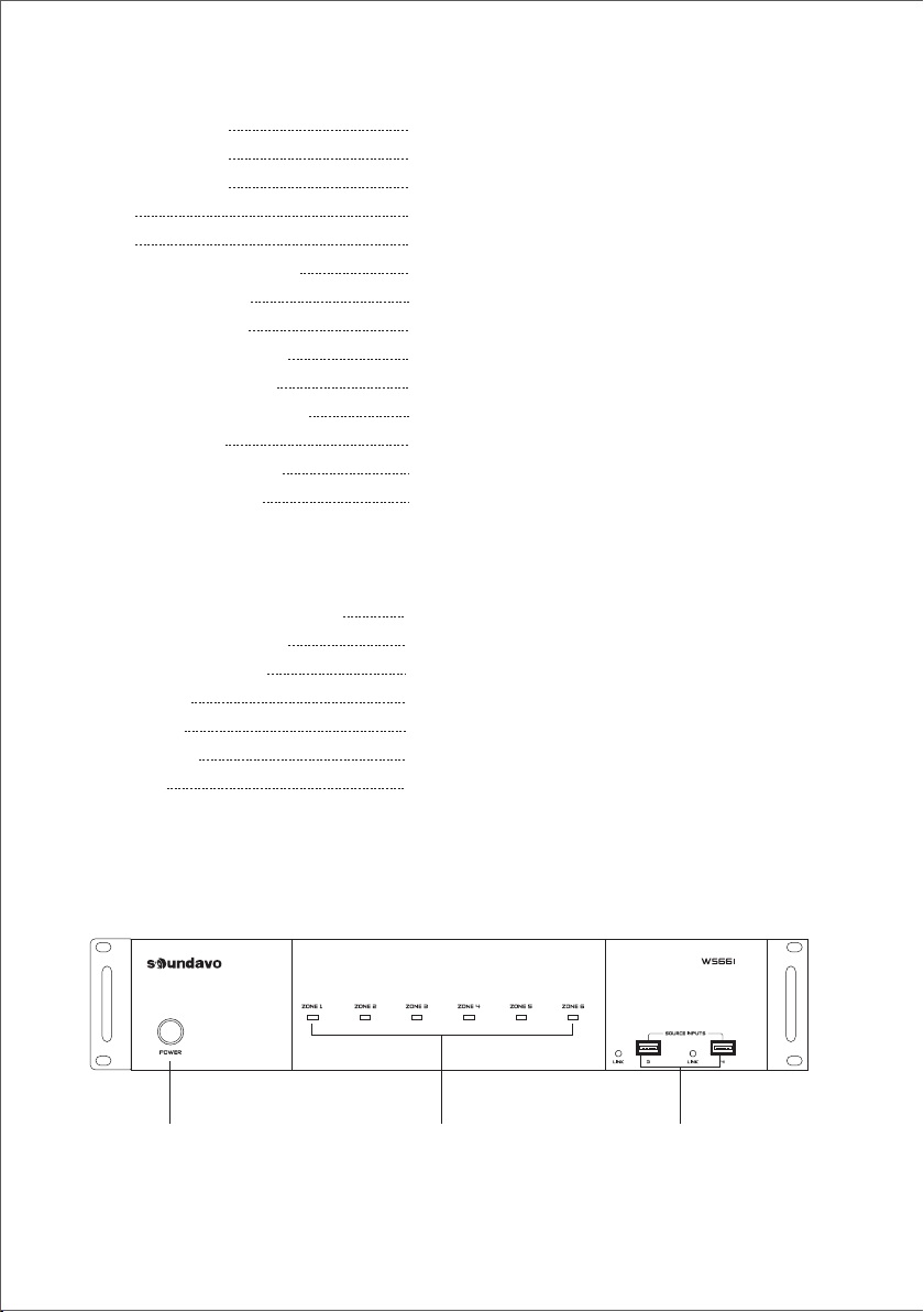
FRONT PANEL
4
>47 KOhm
250 mV
Overload, Short Circuit
DC +12V
DC +12V
AC115V/60Hz, 230V/50Hz
4P Terminal Block
Input 1, 2-RCA Jacks
Input 3, 4–Streamers or USB ports
Input 5–3.5mm Jack
Input 6–S/PDIF, 3.5mm Jack
Up to 24Bit/192KHz with popular audio format
MP3/WMA/AAC/AAC+/ALAC/FLAC/APE/WAV
DLNA, AirPlay
USB2.0, Support up to 64G.

1. Power ON/OFF/ STANDBY
Depress the power button to turn
on the system. Press it again to
release the latch and power the
unit off. Note that even the Master
Controller is powered on, each
zone will remain in Standby mode
until the zone keypad is activated.
1 3 5 4 10 12
13 14 15 17
11 16
2 6 7 8 9
REAR PANEL
1. PRE-AMP OUTPUT
Stereo Line level output on each zone.
Connect to additional amplifier with higher
output, or powered Sub-woofers.
2.SPEAKER OUTPUTS
6 x Removable terminal block connectors
on each zone.
3.STEREO/BRIDGE SWITCH
4.SOURCE INPUTS
6 Stereo Analog/Digital inputs.
Two Wi-Fi Streamers are input 3 and 4.
5.Input 1/PA
Paging capability for Input 1 to broadcast
to all zones when 12VDC is applied to the
PA - IN jack.
6.STATUS
When the zone is activated, the corresponding
jack will output 12VDC to trigger other device.
7.IR EMITTERS
IR Outputs 6 routed & 1 common
8.PA-IN
12VDC paging trigger input
9.EXT. MUTE/CONTROL OUT
Mute the entire system with the 12VDC MUTE IN.
Use the12VDC CONTROL OUT to trigger other
equipment
10.EXPANSION IN/OUT PORT
Expandable to 18 zones with 3 x Multi-zone
Controller systems.
11.ETHERNET PORTS
Dual LAN ports, one connects to the LAN port of
local router. Another connects to network TV or
other device which requires Ethernet.
2. Standby/Zone ON LED
These six LEDs illuminate to indicate the
status of each zone.
3. USB Port 3/4
Two USB ports correspond to the built-in
Wi-Fi Streamers, as source input 3 and 4.
Playing audio source from USB Flash
Drives.
5
Blue: In Standby mode. White: In Activate
mode. Blue/White: In Mute mode.
Each zone provides 2x50W @4Ohm
or 100W @8Ohm in bridge mode.
12.ETHERNET/RS232 SWITCH
ETHERNET: When the amplifier connects to
Ethernet.
RS232: When the amplifier control by PC or
Control Device via RS-232.
13.AGC
Automatic Gain Control, brings low level up
to a present-level.
14.MASTER/SLAVE SWITCH
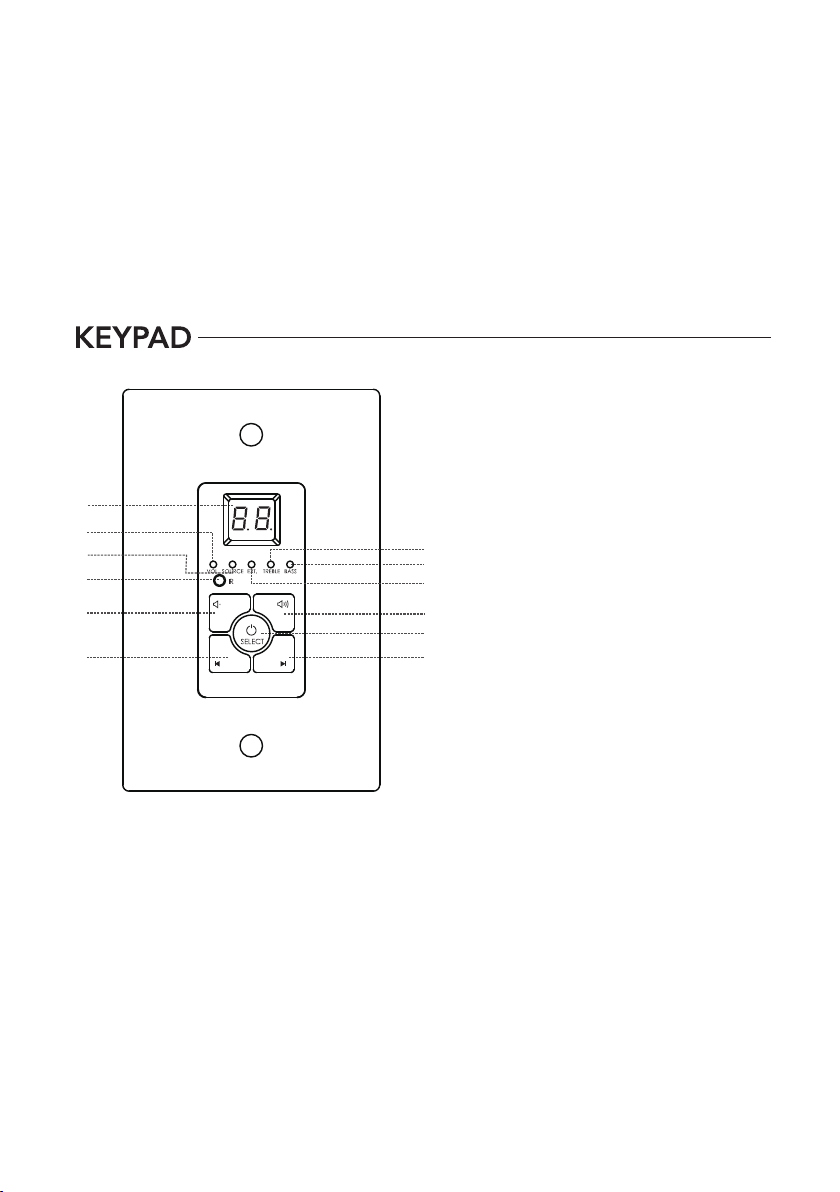
1. Numeric LED Display: The digital LED
display show the number of the source
device, as well as the volume, treble,
and bass level.
2. VOL. LED: When illuminated, this LED
indicates that the Numeric LED is
displaying the volume level. Use the Up
and Down buttons to increase and
decrease the volume level.
3. Source LED: When illuminated, this
LED indicates that the Numeric LED is
displaying the source selection.
4. EXT. LED: When illuminated, this LED
indicates that the Mute function is
enabled or that a PA broadcast is in
progress
5. Treble Mode LED: When illuminated,
this LED indicates that the Numeric
LED is displaying the treble level. Use
the Up and Down buttons to increase
and decrease the treble level.
Set the unit ID when connecting multi
Controller systems
15.KEYPAD
RJ-45 jack Connects to the keypad hub
for 6 keypads.
16.VOLTAGE SELECT
Please set to correctly input voltage
before turn on the amplifier.
17.AC INPUT
1
2
10
9
7
3
6. Bass Mode LED: When illuminated, this LED indicates that the Numeric LED is displaying the bass
level. Use the Up and Down buttons to increase and decrease the bass level.
7. Infrared (IR) receiver: The IR “eye” receiver the infrared remote control signals. Signals sent from the
include remote control are used to control the wall plate keypad.
8. Up Button: Use this button to increase the volume, treble, or bass levels (depending on which mode
is selected). If the zone is muted, pressing this button will unmute it.
9. Down Button: Use this button to decrease the volume, treble, or bass levels (depending on which
mode is selected). If the zone is muted, pressing this button will unmute it.
10. Previous Source Button: Use this button to cycle backwards through the list of available source.
For example, if source 3 is currently selected, pressing this button will change to source 2.
11. Next Source Button: Use this button to cycle forwards through the list of available source. For
example, if source 3 is currently selected, pressing this button will change to source 4.
12. Select-Power Button: Press and hold this button for about 3 seconds to turn the zone on or off.
When the zone is on, pressing the button will cycle through the availale adjustment modes.
6
5
6
4
8
12
11

1
7
2
5
6
3
4
3
7

WS66I
WS66I
RCA 3.5mm Stereo
8

The WS66I can work with speakers that are 4-8 Ohm. There are 9 two
modes that can be set for different setups: Stereo or Bridge. An 8 Ohm
speaker can only be used when in Bridge mode. To choose between modes,
use the mode switch to determine modes for each zone (Number 2 Panel
Descriptions, page 5)
STEREO MODE BRIDGE MODE
and network.
9
6
6
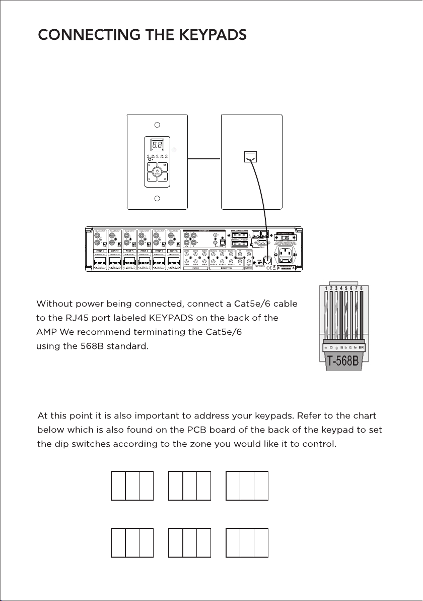
ZONE-1
ON ON OFF
1 2 3
ZONE-2
ON ONOFF
1 2 3
ZONE-3
ON OFFOFF
1 2 3
ZONE-4
ONONOFF
1 2 3
ZONE-5
ON OFFOFF
1 2 3
ZONE-6
ONOFFOFF
1 2 3
10
(Optional)
The WS66I can be controled via 6POE enabled keypads (optional). This allows for
source control from each specific zone as well as IR routing to the
appropriate source devices once selected. The WS66I also comes with
optional hub that allows for all 6-keypads to be connected to the amp via
Cat5e/6.

WS66I
FRONT BACK
reserved for cascading units
12VDC out to trigger
external amplifier
11

12
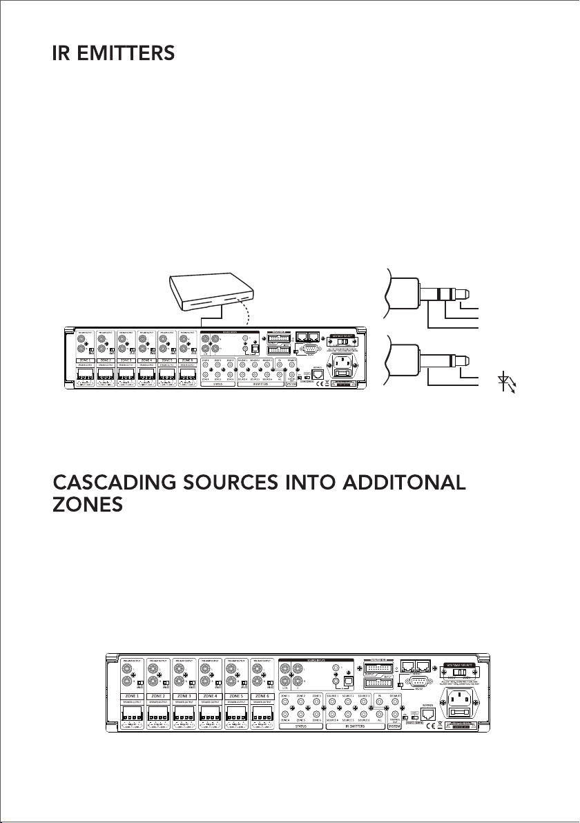
When being used with keypads, the WS66I can receive IR signals from each
zone, and routed back through the Cat5e/6 and Keypad up to the Amplifier to
control the selected source. For example, if Source 2-DVD is selected in Zone 1,
the user will be able to control the DVD player to power the device on/o,
change settings ect. Since the amplifer has discreet routing, ONLY the Source
that is selected on each zone can be controlled. This prevents other sources
from accidently be controlled when selected on other zones.
The WS66I can allow 6 sources to be distributed to up to 18 zones on 3 dierent
units using the provided ribbon cable to connect between units. To do this first
each unit needs to be addressed according using the MASTER/SLAVE switch.
There are 3 positions for this, Master, Slave 1, and Slave 2 which help identify
each unit.
Source 2-DVD
IR Emitter from
Source 2 port
Power
IR Signal
Grounding
IR +
IR -
13

Master
SLAVE 1
SLAVE 2
SOURCE INPUTS
1 / PA 2
ZONE 1 ZONE 2 ZONE 3
ZONE 4 ZONE 5 ZONE 6
STATUS
ZONE 1
SPEAKER-OUTPUT
L
R
R
L
PRE-AMP OUTPUT
Bridge 8Ω
4/8Ω 4/8Ω
ZONE 2
SPEAKER-OUTPUT
L
R
R
L
PRE-AMP OUTPUT
Bridge 8Ω
4/8Ω 4/8Ω
ZONE 3
SPEAKER-OUTPUT
L
R
R
L
PRE-AMP OUTPUT
Bridge 8Ω
4/8Ω 4/8Ω
ZONE 4
SPEAKER-OUTPUT
L
R
R
L
PRE-AMP OUTPUT
Bridge 8Ω
4/8Ω 4/8Ω
ZONE 5
SPEAKER-OUTPUT
L
R
R
L
PRE-AMP OUTPUT
Bridge 8Ω
4/8Ω 4/8Ω
ZONE 6
SPEAKER-OUTPUT
L
R
R
L
R
L
PRE-AMP OUTPUT
Bridge 8Ω
4/8Ω 4/8Ω
BRIDGE
YES NO
BRIDGE
YES NO
BRIDGE
YES NO
BRIDGE
YES NO
BRIDGE
YES NO
BRIDGE
YES NO
12V Trigger
output
MAP-1200HD
DVD
Stereo Amplifier
or Powered
Subwoofer
14
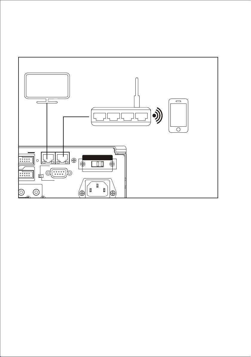
ETHERNET CONNECTION
KEYPADS
ETHERNET
Reset
RS232
MASTER
AGC
SLAVE 2
SLAVE 1
YES / NO
AC: 115V ~ 60Hz, 1250W FUSE: T10AL 250V
AC: 230V-240V ~ 50Hz, 1250W FUSE: T5AL 250V
VOLTAGE SELECT
115V 230V
SYSTEM
CONTROL
EXT.MUTE
IR EMITTERS
PA
OUT
SOURCE 3
ALLSOURCE 6
EXPANSION
OUTPUT
INPUT
Network TV
Router
APP
There are two RJ-45 jacks on the rear panel of this amplifier for the connection to
Ethernet.
Please use a good quality Cat5e/5 cable, and follow the connecting diagram
below.
2.Connect the LAN2 port on the rear panel of control to the smart TV or other
Network devices.
The port simply works as SWITCH function as long as the LAN1 port enabled to
Ethernet.
1.Connect the LAN1 port on the rear panel of controller to the local Wi-Fi Router.
The Ethernet connection mainly for Wi-Fi control via APP or other control devices.
15
Note: When controlling via ETHERNET, please make sure the ETHERNET/RS232
switch is set at ETHERNET position.

CONNECTION DIAGRAM
KEYPADS
6
ETHERNET
Reset
5
RS232
MASTER
AGC
SLAVE 2
SLAVE 1
YES / NO
AC: 115V ~ 60Hz, 1250W FUSE: T10AL 250V
AC: 230V-240V~ 50Hz, 1250W FUSE: T5AL 250V
VOLTAGE SELECT
115V 230V
SOURCE INPUTS
1 / PA 2
SYSTEM
CONTROL
EXT.MUTEZONE 1 ZONE 2 ZONE 3
ZONE 4 ZONE 5 ZONE 6
IR EMITTERS
PA
STAT US
OUT
SOURCE 1 SOURCE 2 SOURCE 3
ALLSOURCE 4 SOURCE 5 SOURCE 6
EXPANSION
OUTPUT
ZONE 1
SPEAKER-OUTPUT
L
R
R
L
PRE-AMP OUTPUT
Bridge 8Ω
4/8Ω 4/8Ω
ZONE 2
SPEAKER-OUTPUT
L
R
R
L
PRE-AMP OUTPUT
Bridge 8Ω
4/8Ω 4/8Ω
ZONE 3
SPEAKER-OUTPUT
L
R
R
L
PRE-AMP OUTPUT
Bridge 8Ω
4/8Ω 4/8Ω
ZONE 4
SPEAKER-OUTPUT
L
R
R
L
PRE-AMP OUTPUT
Bridge 8Ω
4/8Ω 4/8Ω
ZONE 5
SPEAKER-OUTPUT
L
R
R
L
PRE-AMP OUTPUT
Bridge 8Ω
4/8Ω 4/8Ω
ZONE 6
SPEAKER-OUTPUT
L
R
R
L
R
L
PRE-AMP OUTPUT
Bridge 8Ω
4/8Ω 4/8Ω
BRIDGE
YES NO
BRIDGE
YES NO
BRIDGE
YES NO
BRIDGE
YES NO
BRIDGE
YES NO
BRIDGE
YES NO
INPUT
12V Trigger
output
WS66I Network TV
Router
APP
DVD
Stereo Amplifier
or Powered
Subwoofer
16

The Ethernet connection of the WS66I is used for configuration and program-
ming as well as for enabling control via the WS66I control APP, and the “Sounda-
vo Player” for the built-in streaming services and for playing any music stored on
connected network. By using the Advanced_IP_Scanner software can be used to
search for the WS66I matrix amp device in the local area network, IP address and
status. Connect an Ethernet cable from an open network port on the rear of the
WS66I, the LED beside the ethernet port of will turns flash green when the
network connection is successfully established.
INTEGRATED NETWORK
1. Open the IE web browser of PC, log in to the WEB configuration page of local
Router to find the IP address of WS66I (shown as below)
Please switch to MASTER and ETHERNET.
Note. Please do not press “Reset” button.
Note. Please do not connect the Ethernet port of
WS66I to the computer directly.
WS66I
17
Important Notice

Then enter the IP address of WS66I to the IE browser (shown
as below), ensure the Serial Configure is 9600,n,8,1. After finishing
this step, WS66I could be controlled through the local Network.
18
2.Using “Advanced_IP_Scanner” software to find the “HLK-RM04 or
WS66i”IP address. Please visit www.advanced-ip-scanner.com for free
download.

Download free software “PuTTY” Tool from the internet to control the device.
Operation diagram as below:
19

Click Telnet, enter the IP address of WS66I and port: 8080.
Click Open.
When the IP address connected, the operation diagram shows as below:
Key in the command code to control WS66I.
For the detail of command codes, please find the RS-232 command codes in this
instruction manual.
20
Other manuals for WS66I
1
Table of contents
Other Soundavo Amplifier manuals

Soundavo
Soundavo PSA-4600 User manual

Soundavo
Soundavo PSA-1250V User manual

Soundavo
Soundavo PSB-1000 DSP User manual

Soundavo
Soundavo M66-EXT User manual

Soundavo
Soundavo NSA-250 User manual

Soundavo
Soundavo CSA-60 User manual

Soundavo
Soundavo WS66I User manual

Soundavo
Soundavo PSB-300 User manual

Soundavo
Soundavo PSA-50H User manual

Soundavo
Soundavo MZ-1650S User manual


