SoundBrick 550N User manual

SoundBrick550N 11/2007
INSTALLATION AND OPERATION MANUAL
SoundBrick
Model 550N
Quick install
instructions
on back cover
Please leave this manual with the unit at all times
Important warranty information enclosed

SoundBrick550N 11/2007
2
TABLE OF CONTENTS
What is the SoundBrick 550N?..........................................................................3
System Overview...............................................................................................5
Front Panel...............................................................................................5
Connections Panel....................................................................................7
Tape Preparation Instructions............................................................................8
Both MOH and Night Answer Tape...........................................................8
MOH Only Tape........................................................................................8
Night Only Tape........................................................................................8
Message Length Table.......................................................................................9
Installation........................................................................................................10
Step 1 – Set the option switches.............................................................10
Night Message Size, Switch 1.......................................................11
Bandwidth, Switch 2 ......................................................................11
Password Select, Switches 3-4 .....................................................11
Night Answer Rings, Switches 5-6.................................................11
Night Answer On/Off, Switch 9......................................................11
Speaker On/Off, Switch 10............................................................11
Step 2 – Connections .............................................................................12
Step 3 – Load Messages........................................................................13
Tape Load .....................................................................................13
Phone Load/Remote Access.........................................................14
Step 4 – Adjust Volume ..........................................................................15
Message Play Operation..................................................................................16
MOH Message Play................................................................................16
Night Answer .........................................................................................16
Wall Mounting Instructions...............................................................................17
Troubleshooting ...............................................................................................19
Quick Install instructions ..................................................................................20
LIST OF FIGURES
Figure 1 - Front Panel Diagram..........................................................................5
Figure 2 - Side Panel Diagram...........................................................................7
Figure 3 - Option Select Switches....................................................................10
Figure 4 - Installation Diagram.........................................................................12
LIST OF TABLES
Table 1 - Play Light + Load Light Indications.....................................................6
Table 2 - Status Light (Night Answer) Indications..............................................6
Table 3 - Message Length .................................................................................9
Table 4 - Option Select (DIP) Switches............................................................10
Table 5 - Password Select...............................................................................11
Table 6 - Load Light Indications (Tape Load) ..................................................14
Table 7 - Phone-Load User Menu....................................................................15

SoundBrick550N 11/2007
3
WHAT IS THE SOUNDBRICK 550N?
The SoundBrickModel 550N is a solid-state digital audio recording and
playback device designed to provide a continuous-loop audio source for telephone
message on hold (MOH) plus a night answer feature. The message on hold and
night answer audio programs load into the SoundBrick’s digital flash memory
automatically from your pre-recorded cassette tape and can also be loaded remotely
using a standard touch-tone telephone.
During the day the SoundBrick 550N provides message-on-hold audio to your phone
system. When night answer is activated, the unit continues to play the MOH
message until an incoming call is detected. After the selected number of rings, the
unit answers the call, plays the 30- or 60-second night answer message, then
disconnects. Night answer can be activated manually using a switch on the unit or
can be set to turn on and off automatically at pre-set times by connecting the optional
24-hour/7-day digital timer and 1/8” mini-plug trigger cable. This optional timer
ensures night answer is operational at the correct times each day and eliminates the
chance of lost calls should the staff forget to turn off the night answer switch.
The SoundBrick 550N is the most versatile digital player of its kind, with a list of
features that includes:
9User-selectable 6.5KHz or 11.5KHz bandwidth
94, 8, 16, 32, or 64 minutes of messages
9Night answer function with separate 30- or 60-second night message
9Internal motorized CD-style tape drawer
9Automatic night answer activation using optional timer and 1/8” mini-plug trigger
cable
9Password-protected remote audio load
9Flash memory - no battery backup and no messages lost due to power outages
9ADPCM 96dB signal-to-noise ratio for clear, hi-fidelity audio
9User-friendly controls and indicators
9Wall-mountable
9Separate 8and 1KRCA output jacks
9Built-in 2-watt amplifier
Each SoundBrick is built to exacting quality standards using state-of-the-art SMT
(surface mount) assembly for outstanding reliability and years of dependable service.
To get the best possible performance from your SoundBrick, please take the time to
read this manual and fully familiarize yourself with how the SoundBrick works before
you begin installation.

SoundBrick550N 11/2007
4
Use the space below to record information about the SoundBrick and about your
messaging provider. You will need this information should you require assistance
installing or configuring the unit, and when you need a new audio program.
Dealer name:
Contact person:
Phone:
Address:
Serial number
(11 digits):
Memory
(circle one): 4 Min. 8 Min. 16 Min. 32 Min. 64 Min.
SoundBrick550N 11/2007
5
SYSTEM OVERVIEW
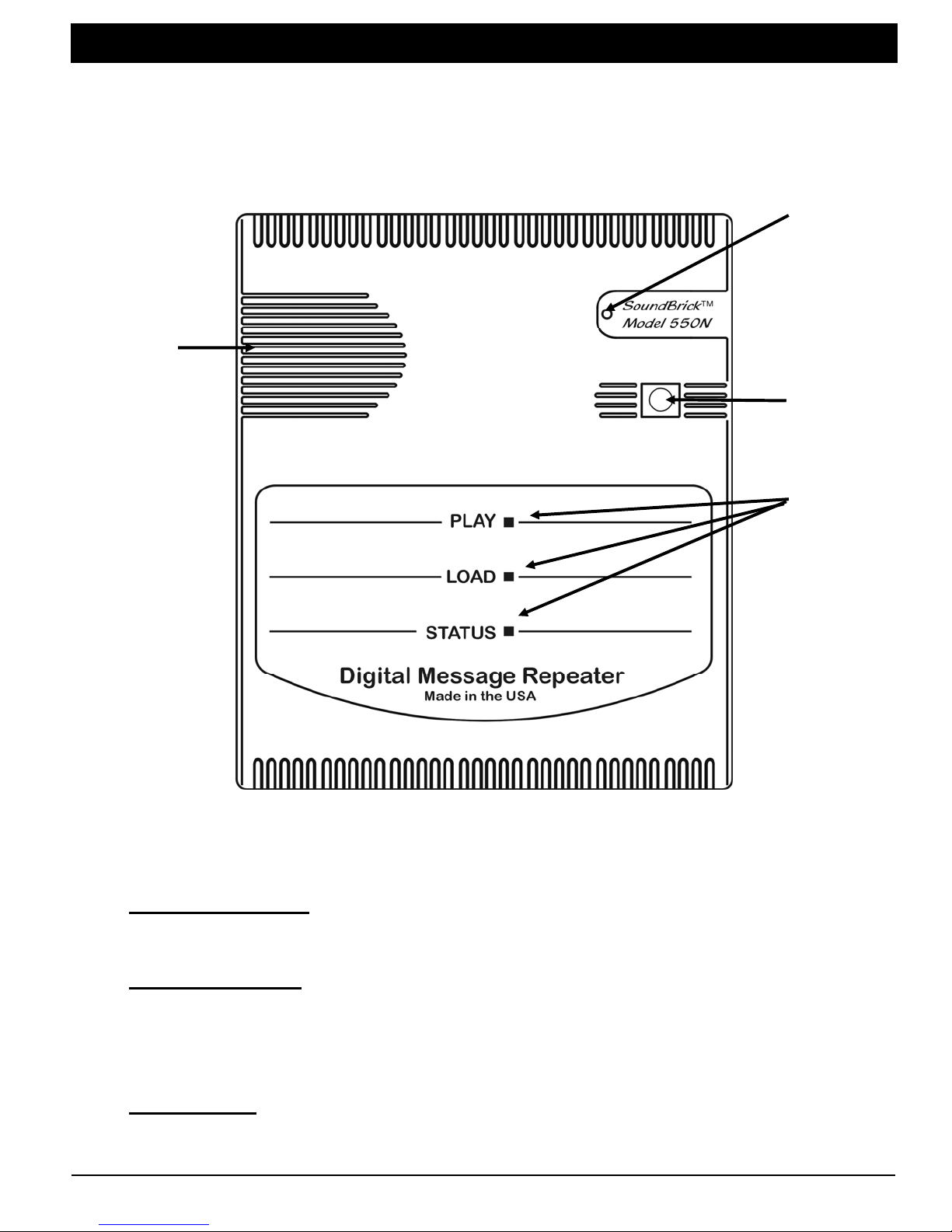
Front Panel
The monitor speaker, tape drawer eject button, and indicator lights are located on
the front panel.
Eject
Monitor
speaker
Main
power
light
button
Play,
load, and
status
lights
Figure 1 - Front Panel Diagram
Main power light – When lit, indicates the power supply is connected and
plugged into an AC outlet and the power switch is on.
Monitor speaker – A built-in speaker, useful for listening to the tape while
downloading and listening to the audio output being provided to the
telephone system’s message on hold port. Note that the speaker’s
volume is not adjustable.
Eject button – Opens and closes the motorized tape drawer for tape loading
and removal. Momentarily pushing the motorized tape drawer will also
result in a closure.

SoundBrick550N 11/2007
6
Play, Load, and Status lights
Play and Load lights — These lights together indicate the current status
of the unit.
Play Light Load Light Indication
Off Slow flash Unit Empty – no tape, no messages
Off Fast flash Searching tape
Off On (no flash) Loading tape now
On (no flash) Off Playing message now
Alternating flash Tape load error
Simultaneous flash Hardware error
Table 1 - Play Light + Load Light Indications
Status light — Displays the current state of the night answer feature.
Status Light Indication
Off Night answer off
On Night answer on, night message loaded
Flashing Night answer on, but no night message loaded
Table 2 - Status Light (Night Answer) Indications
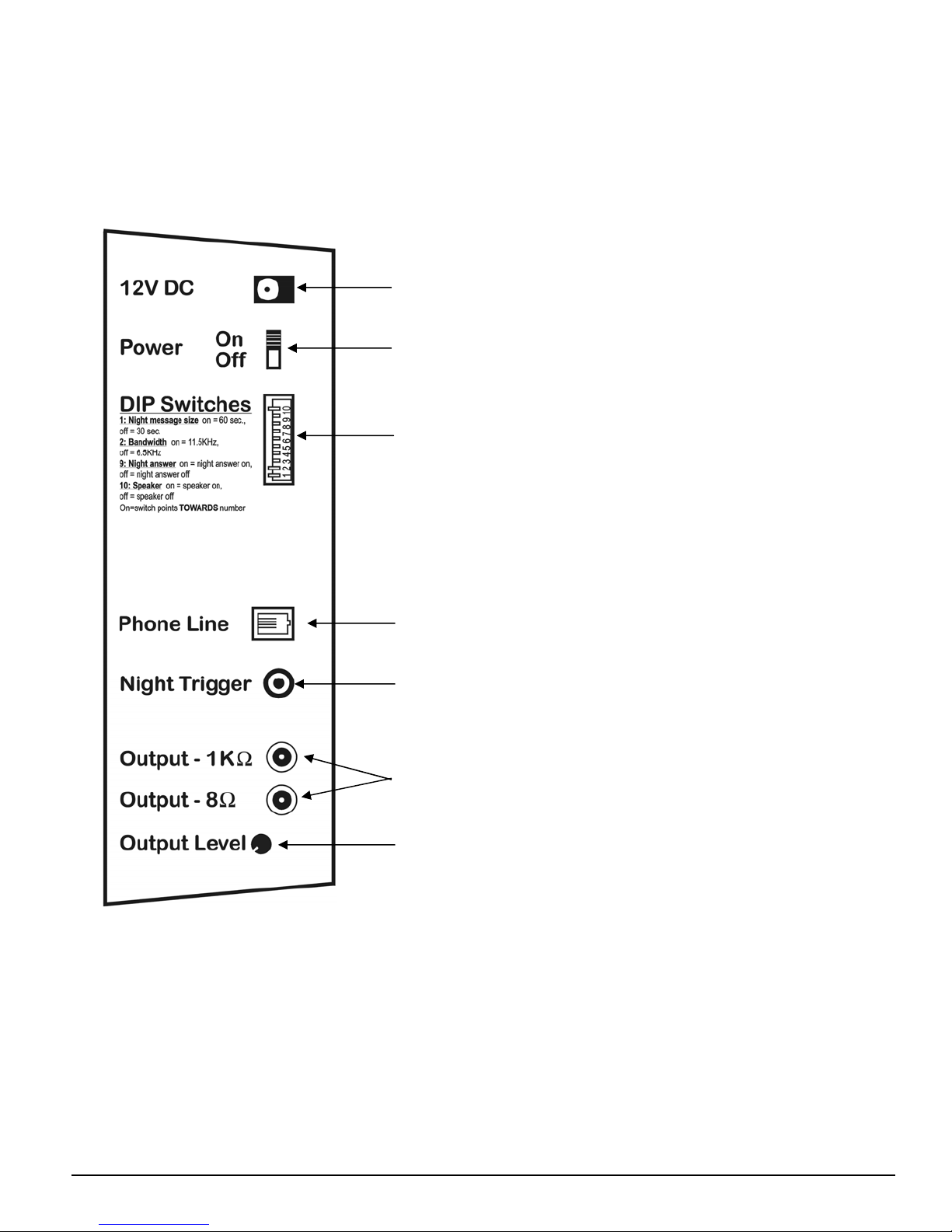
Connections Panel
The left side panel is where the connectors are for external equipment including
the power supply, the phone system that receives the SoundBrick's output, the
night answer telephone line, and the optional external trigger cable. Also located
here are the volume (level) control, the main power switch, and the option select
(DIP) switches.
Power supply connector (12VDC, 500mA, center
pin positive)
Power switch
10 option select (“DIP”) switches used to set
night answer message size, bandwidth,
passwords, night answer rings, night answer
on/off, and internal speaker on/off
RJ-11 telco connector for night answer phone line
Connector for the 1/8” mini-plug trigger cable
(optional part) for remote message activation
RCA connectors for phone system’s MOH port.
Separate 8and 1Koutputs provided for
impedance matching
Output level adjustment knob
Figure 2 - Side Panel Diagram
SoundBrick550N 11/2007
7

SoundBrick550N 11/2007
8
TAPE PREPARATION INSTRUCTIONS
To get the best audio reproduction, it is essential to start with a high-quality
recording. In order to load into memory properly, your audio tape program must
conform to the following guidelines exactly.
1. Use only normal bias (Type I) tapes not exceeding 90 minutes in capacity.
2. Do not use high bias, chrome, or metal tapes.
3. Do not use DOLBYor any other noise reduction system.
4. Record your production in 2-channel mono. The audio level should average
0dB while peaking no hotter than +6dB.
Sequencing required for the MOH and night message depends on what the tape will
contain:
1. Both MOH and night message,
2. MOH message only, or
3. Night message only
Both MOH and Night Answer Tape
less than 20
seconds
silence
MOH
message 10 seconds
silence Night
message
at least 30
seconds
silence
Record the MOH message first, less than 20 seconds from the beginning of the
tape. Leave 10 seconds of silence after the MOH message. Record the night
answer message next. Leave at least 30 seconds of silence after the night
answer message.
MOH Only Tape
less than 20
seconds
silence
MOH
message
at least 30
seconds
silence
Start the MOH message less than 20 seconds from the beginning of the tape.
Leave at least 30 seconds of silence after the message.
Night Only Tape
at least 30
seconds
silence
Night
message
at least 30
seconds
silence
Start the night message at least 30 seconds from the beginning of the tape.
Leave at least 30 seconds of silence after the message.

SoundBrick550N 11/2007
9
MESSAGE LENGTH TABLE
Message length is determined by the memory size of your unit and the bandwidth
setting. The 11.5KHz bandwidth setting provides better audio quality than the
6.5KHz setting but also reduces the total recording time by one-half.
To determine the size of the MOH message, subtract the night message size (30 or
60 seconds—option select switch 1) from the total memory as shown below.
Memory Size Bandwidth Night
Message
4 Min. 8 Min. 16 Min. 32 Min. 64 Min.
MOH
Message
Size
3:30 7:30 15:30 31:30 63:30 6.5 KHz 30 sec.
3:00 7:00 15:00 31:00 63:00 6.5 KHz 1 min.
1:30 3:30 7:30 15:30 31:30 11.5 KHz 30 sec.
1:00 3:00 7:00 15:00 31:00 11.5 KHz 1 min.
Table 3 - Message Length
SoundBrick550N 11/2007
10
INSTALLATION
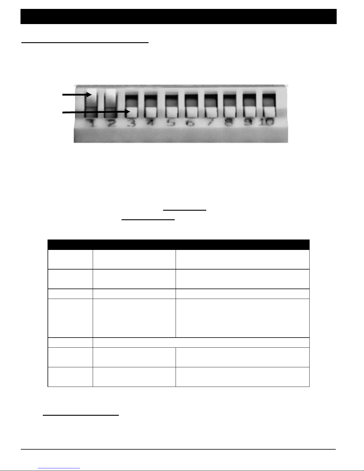
Step 1 – Set the option switches
Set the option select “DIP” switches to match your requirements for night message
size, bandwidth, passwords, night answer rings, night answer on/off, and internal
speaker on/off.
“off”
“on”
Figure 3 - Option Select Switches
This example is for illustrative purposes only.
Your actual switch settings will vary.
A switch is “on” when it is pointing TOWARDS the switch numbers. The switch is
“off” when it is pointed AWAY FROM the switch numbers. In the picture shown
above, switches 1 and 2 are “off” and switches 3 through 10 are “on.”
Switch # Option Possible Values
1 Night message size On = 60 seconds
Off = 30 seconds
2 Bandwidth On = 11.5KHz
Off = 6.5KHz
3-4 Password select See table 4
5-6 Night answer rings
5 off, 6 off = 1 ring
5 on, 6 off = 2 rings
5 off, 6 on = 4 rings
5 on, 6 on = 8 rings
7-8 Not used
9 Night answer On = Night answer on
Off = Night answer off
10 Internal speaker On = Speaker on
Off = Speaker off
Table 4 - Option Select (DIP) Switches
IMPORTANT NOTE: Changes to the night message size and bandwidth
settings do not take effect until power is recycled and messages
reloaded. Changes to password select and night answer rings do not
take effect until power is recycled.

SoundBrick550N 11/2007
11
Night Message Size, Switch 1
Sets the maximum length for the night answer message. This time is
subtracted from the total time available for the MOH message.
Bandwidth, Switch 2
Sets the fidelity of audio messages. There is a trade-off between audio quality
and recording time, the higher the audio quality, the less the storage time.
The minutes of memory equipped on your unit (4, 8, 16, 32, or 64) is printed on
the serial number label on the rear of the unit, and assumes a bandwidth
6.5KHz. The 11.5KHz setting provides better audio quality, but reduces the
amount of recording time by one-half (i.e. a 16 minute unit can only store 8
minutes of audio). See the message memory table on page 9for audio storage
times for different memory and bandwidth configurations.
Password Select, Switches 3-4
Sets the MOH and night message remote-access passwords. When you dial
into the unit to phone-load the MOH or night message, the appropriate
password must be entered by touch-tone.
SW3 SW4 MOH Password Night Password
OFF OFF 2468 1234
OFF ON 6453 5384
ON OFF 4655 7262
ON ON 2463 5673
Table 5 - Password Select
Night Answer Rings, Switches 5-6
Sets how many rings night answer waits before answering calls.
Night Answer On/Off, Switch 9
Turns the night answer feature on or off. Note that the position of this switch
does not necessarily indicate the current status of night answer because when
the switch is off night answer can still be turned on using the trigger function.
However, if the switch is on then night answer is definitely on and triggers are
ignored. The current state of night answer is indicated by the status light on the
front panel (see status light table on page 6for details).
Speaker On/Off, Switch 10
This switch turns the internal speaker on (switch on) and off (switch off). Note
the speaker’s volume cannot be adjusted. The output level knob on the side
panel only adjusts the level of the signal provided to the phone system, not the
volume of the internal speaker.
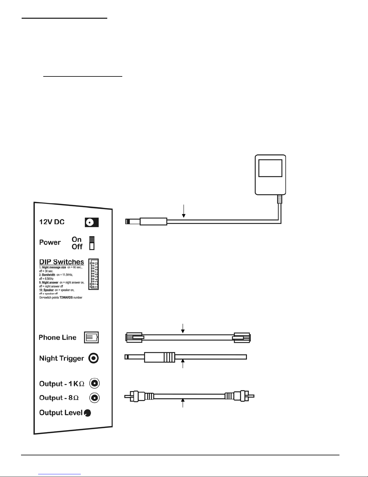
Step 2 – Connections
Locate the SoundBrick 550N within 6 feet of a 110VAC outlet. The unit is
designed to be placed on a flat, level surface or securely mounted on a wall. Be
sure to leave clearance for connections and adjustments.
IMPORTANT NOTE: Devices that emit strong electromagnetic fields such
as computer monitors and fluorescent lights may interfere with message
loading, so locate the unit at least a few feet away (or farther if necessary)
from such devices.
To help protect against power surges and other electrical problems, the use of a
quality surge suppressor strip (which is different from a standard multi-outlet
power strip) is strongly recommended. Damage caused by power surges,
lightning, or other electrical problems are not covered under warranty.
12VDC power supply (included)
RJ-11 telco cable (included)
1/8” mini-plug trigger cable (optional)
Connect to phone
system’s MOH
port
Connect to timer
Connect to phone
line
or trigger hardware
mono RCA cable (included)
Figure 4 - Installation Diagram
SoundBrick550N 11/2007
12

SoundBrick550N 11/2007
13
Connection Instructions
1. Turn the power switch off. Plug the included power supply into a surge-
protected 110VAC outlet and the 12VDC jack on the SoundBrick 550N. Only
use the power supply provided with the unit (12VDC, 500mA, center pin
positive). Many power supplies look alike, but provide different output. Using
the wrong one will void your warranty and may damage the unit.
2. Connect either the 8or 1Kaudio output jack to the phone system’s MOH
port using a mono RCA-to-RCA cable (included). If the sound system does not
have an RCA-style input, an adapter may be required (not included).
3. If you are using the night answer feature, select the incoming phone line to be
answered by the unit and split the line. For proper night answer operation you
must use the first phone line normally answered by the company’s phone
system. Connect one side of the split to the phone line’s original destination.
Connect the other side of the split to the phone line jack on the SoundBrick
using an RJ-11 telco cable (included).
IMPORTANT NOTE: The SoundBrick 550N must only be connected to a
standard analog loop-start telephone line, ahead of any other equipment
using that line. Installation on any other type of line, or on a KSU or PBX
extension will fail and may damage the other equipment and/or the
SoundBrick. To test the installation line, connect a normal analog home
telephone to the line. If the line type is correct, you will be able to place
an outgoing call and receive an incoming call using the home telephone.
4. Connect the optional 1/8” mini-plug trigger cable to the optional timer or other
trigger hardware if you are using this feature.
Step 3 – Load Messages
Messages load into the SoundBrick 550N from a cassette tape supplied by your
messaging provider and can also be loaded remotely by dialing into the unit using
a standard touch-tone phone.
Tape Load
Turn the power switch on and press the tape eject button. The motorized tape
drawer on the right side of the unit opens like a CD-ROM drive on a computer.
Place the tape into the drawer by gently sliding it under the retaining clip, audio
side facing front, then press the eject button, or momentarily push the drawer to

SoundBrick550N 11/2007
14
close. The SoundBrick detects the presence of the tape and begins the load
process automatically.
After tape insertion, the load light on the front panel flashes slowly and the unit
rewinds the tape. Because the MOH and night answer messages are stored in
different sections of memory, the unit must scan the tape to determine which
message(s) it contains. If it finds less than 20 seconds of silence at the
beginning, the tape is either MOH only or MOH+night. If it finds at least 30
seconds of silence at the beginning, then the tape is night message only. After
the initial scan is complete, the tape rewinds again and message loading
begins. Never eject the tape while it is loading.
During tape load, the load light display the progress:
Load Light Indication
Slow flash No tape in machine or rewinding tape
Fast flash Searching tape for audio
On (no flash) Loading message now
Table 6 - Load Light Indications (Tape Load)
At the end of message loading, the tape rewinds and message play begins
automatically, indicated by a solid play light.
IMPORTANT NOTE: Once the SoundBrick is loaded and playing, you do
not have to leave the tape in the unit. The audio program is stored in non-
volatile flash memory which is not erased if power is lost or if the unit is
turned off. However, we recommend leaving the tape in the unit after
loading. If you do remove the tape, LEAVE IT OUT. If a tape is later re-
inserted the SoundBrick automatically stops message play, erases its
memory and loads the newly inserted tape.
Phone Load/Remote Access
To load by phone, the unit must be properly installed, connected to a standard
analog phone line, and night answer (switch 9) must be on. If switch 9 is off,
the night trigger cable must be installed and activated. In either case, the
status light will be on or flashing.
1. Make sure night answer is on and the unit is installed properly.
2. Dial the SoundBrick’s installation phone number from a different line.
3. The unit answers and plays the night message if one is already loaded.
Press the * (star) key on your phone within 20 seconds. The unit stops
playing the night message and delivers three beeps in response.
4. Enter the MOH password or night password (see password select table,
page 11), depending on which message you want to record . If an invalid

SoundBrick550N 11/2007
15
password is entered, the unit disconnects the call and you must start
over. If the password is correct, you proceed to the next step.
5. Two beeps play, indicating you are now at the user menu. The two beep
tones play any time you finish with a selected option and are returned to
the user menu. There are four user menu options which are selected by
pressing the indicated touch-tone button:
Menu
Option Function Description
1 Play
Plays the selected message through the phone. After
the message finishes playing you are returned to the
user menu. During play, press # once to pause
playback, press * to resume from pause, or press #
twice to exit playback and return to the user menu. If
playback is paused for more than 20 seconds, the call
is disconnected.
2 Erase
Erases the selected message from memory. This
must be done before recording over an existing
message. Press * to start erase. While the message
is being erased, the unit beeps once per second.
After erase is complete you are returned to the user
menu.
3 Record
Records the selected message through the phone.
Important: Before recording, you must first erase
any existing message using option 2 (erase). If
you do not erase first, three beeps play when you
press record and you are returned to the user
menu.
After selecting record the unit beeps once per second,
indicating it is ready to record. To begin recording
press *, then press # when you are finished. You are
then returned to the user menu, where you can play
the new message using option 1 (play) to see if you
like it or would like to record again.
9 Hang up
Hangs up the call. After pressing 9, six beeps play
and the call is disconnected. You may also just hang
up the phone when you are finished.
Table 7 - Phone-Load User Menu
Step 4 – Adjust Volume
After installation and loading is complete, call into the company’s phone system
and ask to be placed on hold. While listening to the on-hold message, adjust the
output level knob on the left side panel as needed.

SoundBrick550N 11/2007
16
MESSAGE PLAY OPERATION
MOH Message Play
The loaded MOH message plays continuously through the audio output jacks.
When the end of the message is reached it plays again from the beginning in a
digital endless loop. This occurs whether night answer is on or off. The MOH
message is only interrupted if night answer is on and an incoming call is received,
as described below.
Night Answer
When night answer is on (switch 9), the SoundBrick continues to provide the MOH
message to the phone system when it is not answering a call. When an incoming
call is received, the unit stops playing the MOH message, answers the call, plays
the night message once, then hangs up. After hanging up, it resumes playing the
MOH message. The current status of night answer is indicated by the status light
on the front panel (see status light table on page 6for details).
Manual On/Off
Use switch 9 to turn night answer on and off (switch on = night answer on,
switch off = night answer off). If connected, make sure the night trigger contact
closure remains open.
Trigger On/Off
To use the night trigger function, switch 9 must be set to off. Night trigger
lets you activate night answer remotely by using the optional 1/8” mini-plug
trigger cable, available from your messaging provider. One end of the trigger
cable plugs into the SoundBrick’s side panel, the other end consists of two
wires. Night answer is turned on by shorting the two wires.
An optional 24-hour/7-day digital timer is available from your messaging
provider which can turn night on and off automatically on a daily schedule. This
saves staff from having to turn it on and off manually and also reduces the
chance of lost calls should the staff forget to turn night answer off.

SoundBrick550N 11/2007
17
WALL MOUNTING INSTRUCTIONS
Using the screw holes on the back plate as a guide, secure two screws into the wall
where you want to mount the unit. Then, hang the unit on the screws.
Consider the weight of the SoundBrick when choosing a mounting wall. Make sure
the wall’s construction is sufficiently strong to support the weight of the unit securely.
Make sure both screws are driven into studs or other sturdy supports, not just into
plain drywall.
To mount in this orientation, the distance between the
centerpoints of the mounting screws should be 3 11/32”.
To mount in this orientation, the distance between the
centerpoints of the mounting screws should be 5 3/8”.

SoundBrick550N 11/2007
18
FCC Notice
WARNING: This equipment has been tested and found to comply with the limits for a Class A digital device
pursuant to Part 15 of FCC Rules. These limits are designed to provide reasonable protection against
harmful interference when this equipment is operated in a commercial environment. This equipment
generates, uses, and can radiate radio frequency energy and, if not installed and used in accordance with
the instruction manual, may cause harmful interference to radio communications. Operation of this
equipment in a residential area is likely to cause harmful interference in which case the user will be required
to correct the interference at his/her own expense.
This digital apparatus does not exceed the Class A limits for radio noise emissions from digital apparatus
set out in the Radio Interference Regulations of the Canadian Department of Communications.
Le présent appareil numérique n'émet pas de bruits radioélectriques dépassant les limites applicables aux
appareils numériques de la Class A prescrites dans le Règlement sur le brouillage radioélectrique édicté par
le ministère des Communications du Canada.
Limited Warranty
TERMS: Nel-Tech warrants to the original purchaser ("Buyer") that the Product sold is free from
defects in material and workmanship at the time of purchase. The warranty extends five (5) years
from the date of original purchase and covers parts and labor. Buyer must provide written notice to
Nel-Tech within the warranty period of any defective part or conditions. If the defect is not the result
of improper use, service, maintenance or installation, and if the equipment has not been otherwise
damaged or modified after shipment, Nel-Tech or its authorized representative shall either replace
or repair the defective Product at Nel-Tech's option. No credit shall be allowed for work performed
by Buyer or unauthorized parties. Out-of-warranty repairs will be invoiced at the current Nel-Tech
hourly rate plus the cost of parts, shipping and handling. IN THE EVENT THAT THE PRODUCT
SERIAL NUMBER IS MISSING OR HAS BEEN TAMPERED WITH IN ANY WAY, THE
FOREGOING WARRANTY IS VOID AND WITHOUT EFFECT AND NEL-TECH SHALL HAVE NO
LIABILITY WHATSOEVER ON ACCOUNT OF DEFECTS TO SUCH PRODUCT.
LIMITATIONS: EXCEPT AS STATED ABOVE, THERE ARE NO WARRANTIES, EXPRESS OR
IMPLIED, THAT EXTEND BEYOND THE SPECIFICATIONS FOR THE PRODUCT. NEL-TECH
EXPRESSLY DISCLAIMS ANY WARRANTY, EXPRESS OR IMPLIED, THAT EQUIPMENT SOLD
HEREUNDER IS OF MERCHANTIABLE QUALITY OR THAT IT CAN BE USED, OR IS FIT FOR
ANY PARTICULAR PURPOSE. BUYER PURCHASES AND ACCEPTS EQUIPMENT SOLELY
ON THE BASIS OF THE WARRANTY HEREINABOVE EXPRESSED. UNDER NO
CIRCUMSTANCES SHALL NEL-TECH BE LIABLE BY VIRTUE OF THIS WARRANTY OR
OTHERWISE FOR ANY SPECIAL, INDIRECT, SECONDARY OR CONSEQUENTIAL DAMAGES
TO ANY PERSON OR PROPERTY ARISING OUT OF THE USE OR INABILITY TO USE THE
PRODUCT.
REPAIRING OR REPLACING PRODUCT: Buyer may obtain the repair or replacement of any
eligible part or equipment covered under this warranty through Nel-Tech only. Buyer is responsible
for all shipping and handling charges in connection with the performance of this warranty. Products
returned to Nel-Tech must be securely packaged to prevent damage in transit, freight prepaid, and
insured for replacement value. A return authorization number assigned by Nel-Tech must be
clearly marked on the outside of the shipping container. Proof of purchase must accompany
shipment. Items delivered to Nel-Tech without a return authorization clearly marked on the outside
of the shipping container, and/or without proof of purchase will be refused. Please contact Nel-
Tech at the address and phone number below to receive a return authorization number and to
arrange for the repair or replacement of a flawed part covered by this warranty. Please indicate the
Product's serial number in all correspondence. an authorization number will not be issued in the
absence of a serial number. Nel-Tech Labs, Inc., 4 Ash Street Extension, Derry, NH 03038, Phone:
(603) 425-1096.
Copyright Notice
This manual Copyright © 1984 - 2008 by Nel-Tech Labs, Inc. All rights reserved. No part of it may
be copied, photocopied, reproduced, translated, or reduced to any electronic medium or
machine-readable form without Nel-Tech's prior written consent.
Information contained herein is subject to change without prior notification. Nel-Tech Labs, Inc.
provides this manual without warranty of any kind, express or implied. This user's manual may
contain technical and/or typographical errors.
SoundBrick is a registered trademark of Nel-Tech Labs, Inc.
Printed in the U.S.A.

SoundBrick550N 11/2007
19
TROUBLESHOOTING
If you have trouble installing or operating the SoundBrick 550N, refer to the table
below to help find a solution. If you are unable to solve the problem yourself, contact
your dealer for further assistance.
Problem or
Indication Possible cause and solution
No MOH message
Unit may be playing night message through phone line.
Can’t play MOH and night message at the same time.
If remote-load feature is currently accessed, MOH
message is halted until call disconnects.
Adjust output level knob.
Check volume or level control on phone system.
No night message Make sure night message is loaded.
Check phone line connection.
Turn night answer on (switch 9).
Doesn’t answer
phone (night)
Check phone line connection—must be line that receives
calls first.
Turn night answer on (switch 9 or trigger).
Change answer rings to lower number (switches 5+6).
Tape load error
(play + load lights
flash together)
Tape is worn out or not prepared to guidelines – obtain
another tape from your messaging provider.
Power interruption occurred during loading.
Possible interference from strong electromagnetic field
(i.e. computer monitor or fluorescent lights) – relocate
unit away from source of interference.
Tape drawer won’t
open If the drawer doesn’t open when you press the eject
button, press eject again.
Tape stuck in deck
or deck is “eating”
tapes
Never eject tape during download. Follow proper tape
load procedure.
To remove stuck tape: Turn power off, wait 10
seconds, turn power on. Wait for deck to disengage play
head before ejecting.
No power-main
power light is off
Check the power switch (should be on).
Check power pack for correct DC output voltage &
current.
Check power outlet to make sure it is not controlled by a
switch.

SoundBrick550N 11/2007
20
QUICK INSTALL INSTRUCTIONS
12VDC power supply
(included)
Connect to phone system’s
For more detailed instructions, read the inside of the manual.
1. Consult message length table (page 9) and tape preparation info. (page 8) if
needed. Set option (DIP) switches:
--Night message size, switch 1 (off = 30 sec., on = 60 sec.)
--Bandwidth, switch 2 (off = 6.5KHz, on = 11.5KHz)
--Password select, switches 3-4 (see table on page 11)
--Night answer rings, switches 5-6 (see table on page 10)
--Night answer on/off, switch 9 (off = night answer off, on = night answer on)
--Speaker on/off, switch 4 (off = speaker off, on = speaker on)
Note: A switch is on when it is pointing towards the switch numbers and
off when it is pointing away from the switch numbers.
2. Connect the power supply and phone system MOH port as shown above.
Connect night answer phone line and optional trigger cable, if applicable.
3. Turn the power switch on. To load by tape, press the eject button on front of the
SoundBrick to open the motorized tape drawer. Insert the cassette into the tape
drawer by gently sliding it underneath the retaining clip, audio side facing front,
then press the eject button, or momentarily push the drawer to close. After an
initial scan of the tape, loading begins automatically. To load messages by
phone, see page 14.
MOH port
Connect to timer or trigger
hardware
mono RCA cable (included)
RJ-11 telco cable (included)
Connect to
p
hone line
1/8” mini-plug trigger cable (optional)
Table of contents


