COMBA SP-9120 Technical Document

EQUIPMENT MANUAL FOR SP-9120
SP-9120 QE Copyright - refer to title page Page 1
ENU Status : 2-0-0
SP-9120
GSM900 BANDWIDTH ADJUSTABLE
PICO REPEATER
EQUIPMENT MANUAL
The information contained herein is the
responsibility of and is approved by the
following, to whom all enquiries should
be directed in the first instance:
International Documentation Centre
Comba Telecom
This is an unpublished work the copyright in which vests in Comba International ("Comba"). All rights reserved.
The information contained herein is confidential and the property of Comba and is supplied without liability for errors or
omissions. No part may be reproduced, disclosed or used except as authorised by contract or other written permission. The
copyright and the foregoing restriction on reproduction and use extend to all media in which the information may be embodied.

EQUIPMENT MANUAL FOR SP-9120
SP-9120 QE Copyright - refer to title page Page 2
ENU Status : 2-0-0
0.2 CONTENTS
Section Page
0.2 CONTENTS ...........................................................................................................................2
0.3 INDEX TO FIGURES AND TABLES .....................................................................................3
0.4 HISTORY...............................................................................................................................3
0.5 ISSUE CONTROL .................................................................................................................3
0.6 REFERENCES ......................................................................................................................3
0.7 GLOSSARY OF TERMS .......................................................................................................3
0.8 SAFETY NOTICES AND ADMONISHMENTS......................................................................3
0.9 SERVICING POLICY AND RETURN OF EQUIPMENT .......................................................3
0.10 READERS COMMENTS .......................................................................................................3
1GENERAL INFORMATION ...................................................................................................3
1.1 GENERAL APPLICATION.....................................................................................................3
1.1.1 USING INTEGRATED ANTENNA.........................................................................................3
1.1.2 USING EXTERNAL ANTENNA (OPTIONAL) .......................................................................3
2EQUIPMENT DESCRIPTION................................................................................................3
2.1 GENERAL..............................................................................................................................3
2.2 SP-9120 SYSTEM DIAGRAM ...............................................................................................3
2.3 EQUIPMENT LAYOUT..........................................................................................................3
2.4 KIT OF PARTS ......................................................................................................................3
2.5 RF SPECIFICATIONS ........................................................................................................... 3
2.6 POWER, MECHNICAL AND ENVIRONMENTAL SPECIFICATIONS..................................3
3INSTALLATION .....................................................................................................................3
3.1 WARNINGS AND ALERTS ...................................................................................................3
3.2 SITE PLANNING CONSIDERATIONS..................................................................................3
3.2.1 REPEATER INSTALLATION CHECKLIST ...........................................................................3
3.2.2 ANTENNA INSTALLATION CONSIDERATION....................................................................3
3.3 INSTALLATION PROCEDURES...........................................................................................3
3.3.1 GOODS INWARDS INSPECTION ........................................................................................3
3.3.2 TOOLS...................................................................................................................................3
3.3.3 PREPARATION .....................................................................................................................3
3.3.4 ANTENNA CONNECTION ....................................................................................................3
3.3.5 WALL MOUNTING ................................................................................................................3
3.3.6 DRIP-LOOP ...........................................................................................................................3
3.3.7 EQUIPMENT CONNECTIONS..............................................................................................3
4COMMISSIONING.................................................................................................................3
4.1 MCU LED INDICATORS .......................................................................................................3
4.2 EQUIPMENT POWER-UP ....................................................................................................3
4.3 DESCRIPTION OF CONTROL PANEL ................................................................................3
4.3.1 DIP Switches .........................................................................................................................3
4.3.2 LCD DISPLAY .......................................................................................................................3
4.4 PROGRAMMING THE SYSTEM...........................................................................................3
4.4.1 EXAMPLES ...........................................................................................................................3
4.5 MCU RESET..........................................................................................................................3
4.6 SYSTEM COMMISSIONING .................................................................................................3
5SYSTEM MAINTENANCE.....................................................................................................3
6APPENDICES........................................................................................................................3
6.1 APPENDIX A: TOOLS FOR INSTALLATION AND MAINTENANCE ...................................3
6.2 APPENDIX B: RMA (RETURN MATERIAL AUTHORIZATION) FORM ...............................3
EQUIPMENT MANUAL FOR SP-9120
SP-9120 QE Copyright - refer to title page Page 3
ENU Status : 2-0-0
0.3 INDEX TO FIGURES AND TABLES
Figure 1: Application with Integrated antenna ......................................................................................3
Figure 2: Application with external antenna ..........................................................................................3
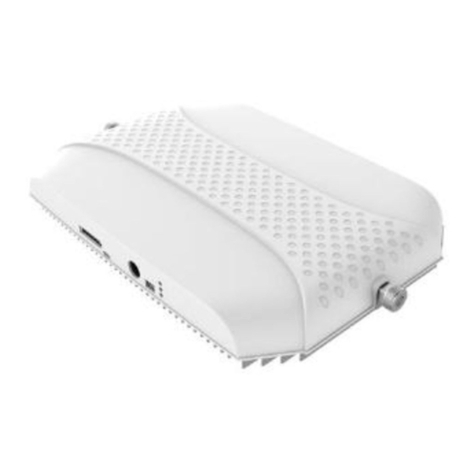
Figure 3: Top, front and side Views of SP-9120 enclosure ..................................................................3
Figure 4: SP-9120 System diagram......................................................................................................3
Figure 5: SP-9120 equipment internal view ..........................................................................................3
Figure 6: Default Integrated Antenna connection (control panel removed for clarity) ..........................3
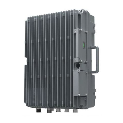
Figure 7: Jumper cable installed (Integrated antenna and control panel removed for clarity) .............3
Figure 8: Mounting arrangement at the rear of the unit .......................................................................3
Figure 9: Alignment of mounting screws...............................................................................................3
Figure 10: Connecting to SP-9120........................................................................................................3
Figure 11: Location of LEDs..................................................................................................................3
Figure 12: Control panel layout .............................................................................................................3
Figure 13: DIP Switch settings on the control panel (OFF and ON).....................................................3
Figure 14: Reset Switch and MCU area ...............................................................................................3
Table 1: SP-9120 KOP..........................................................................................................................3
Table 2: RF specifications.....................................................................................................................3
Table 3: Power, Mechanical and environmental specifications ............................................................3
Table 4: Repeater Installation checklist ................................................................................................3
Table 5: Antenna installation checklist..................................................................................................3
Table 6: LEDs colour and indication .....................................................................................................3
Table 7: numbered function and value displayed on the LCD Display .................................................3

Table 8: Examples of parameters setting .............................................................................................3
Table 9: Default value of each parameter.............................................................................................3
Table 10: Commissioning procedures for SP-9120 ..............................................................................3

EQUIPMENT MANUAL FOR SP-9120
SP-9120 QE Copyright - refer to title page Page 4
ENU Status : 2-0-0
0.4 HISTORY
Change No. ENU Details Of Change
1 1-0-0 Document released on 30th September, 2005
2 1-0-0 Document revised on 17th October 2005 for “RP-9120” is another
model No. for RS-2110F
3 2-0-0 Document updated for CE Certificate with EGSM specifications
included in Dec, 2005.

EQUIPMENT MANUAL FOR SP-9120
SP-9120 QE Copyright - refer to title page Page 5
ENU Status : 2-0-0
0.5 ISSUE CONTROL
Date 30
Sep
05
17
Oct
05
22
Dec
05
Section
All all Front
Sheet &
Section
4.1.1
Section 1
Section 2.5

EQUIPMENT MANUAL FOR SP-9120
SP-9120 QE Copyright - refer to title page Page 6
ENU Status : 2-0-0
0.6 REFERENCES
0.6.1 RS-21110F V1.0 GSM900 Indoor Band Broadband Repeater manual
in Chinese, released in August, 2005
0.6.2 RS-2110F datasheet Issue B,
released on 06-08-2005
GSM900 Indoor Broadband Repeater,
Product Manager: Tommy Sun

EQUIPMENT MANUAL FOR SP-9120
SP-9120 QE Copyright - refer to title page Page 7
ENU Status : 2-0-0
0.7 GLOSSARY OF TERMS
Acronym Definition
ALC Automatic Level Control
ATT Attenuation
BS Base Station
BTS Base Transceiver Station
CDMA Code Division Multiple Access
dB Decibel
dBm Decibels relative to 1 milliwatt
DL DL
DPX Duplexer
DT Donor Terminal
EEPROM Electrically Erasable Programmable Read Only Memory
FS Frequency Selector
FSA Frequency Selector Amplifier
GSM Global System for Mobile Communication
Hz Hertz
ID Identification
LNA Low Noise Amplifier
MCU Main Control Unit
MHz Megahertz
MS Mobile Subscriber
MT Mobile Terminal
MTBF Mean Time Between Failures
NC Normally Closed
NF Noise Figure
NO Normally Open
OMC Operation & Maintenance Centre
OMT Operation & Maintenance Terminal
PA Power Amplifier
PLL Phase Locked Loop
PSU Power Supply Unit
RF Radio Frequency
SMA Sub-Miniature A Connector (coaxial cable connector type)
UL UL
VAC Volts Alternating Current
VSWR Voltage Standing Wave Ratio

EQUIPMENT MANUAL FOR SP-9120
SP-9120 QE Copyright - refer to title page Page 8
ENU Status : 2-0-0
0.8 SAFETY NOTICES AND ADMONISHMENTS
This document contains safety notices in accordance with appropriate standards. In the interests of
conformity with the territory standards for the country concerned, the equivalent territorial
admonishments are also shown.
Any installation, adjustment, maintenance and repair of the equipment must only be carried out by
trained, authorized personnel. At all times, personnel must comply with any safety notices and
instructions.
Specific hazards are indicated by symbol labels on or near the affected parts of the equipment. The
labels conform to international standards, are triangular in shape, and are colored black on a yellow
background. An informative text label may accompany the symbol label.
Hazard labeling is supplemented by safety notices in the appropriate equipment manual. These
notices contain additional information on the nature of the hazard and may also specify precautions.
Warning:
These draw the attention of personnel to hazards which may cause death or injury to the operator or
others. Examples of use are cases of high voltage, laser emission, toxic substances, point of high
temperature, etc.
Alert:
These draw the attention of personnel to hazards which may cause damage to the equipment. An
example of use is the case of static electricity hazard.
Caution notices may also be used in the handbook to draw attention to matters that do not constitute
a risk of causing damage to the equipment but where there is a possibility of seriously impairing its
performance, e.g. by mishandling or gross maladjustment. Warnings and Cautions within the main
text do not incorporate labels and may be in shortened form.

EQUIPMENT MANUAL FOR SP-9120
SP-9120 QE Copyright - refer to title page Page 9
ENU Status : 2-0-0
0.9 SERVICING POLICY AND RETURN OF EQUIPMENT
The repair of individual units and modules of this equipment is not considered practicable without
factory facilities. It is, therefore, the policy of Comba whereby faulty units or modules are returned to
the local agent for repair.
To enable an efficient, prompt after sales service to be provided for the diagnosis, repair and return
of any faulty equipment, please comply with the following requirements.
Items to be sent for repair should be packaged so as to provide both electrostatic and physical
protection and a Repair Material Authorization (a sample of this form is in the appendix) completed
giving the required information
This request must be included with the item for repair, items for repair should be sent to the nearest
Comba office:
COMBA TELECOM SYSTEMS, LTD.
Hong Kong Office
Address: Room 1503-10 Delta House, 3 On Yiu Street, Shatin, Hong Kong.
Tel: + 852 2636 6861
Fax: + 852 2637 0966
Singapore office
Address: 865 Mountbatten Road #05-43, Katong Shopping Centre, Singapore 449408
Tel: + 65 6345 4908
Fax: + 65 6345 1186
Sweden Office
Address: Comba Telecom Systems AB, Gustavslundsvagen 147, S- 167 51 Bromma,
Stockholm, Sweden
Tel: +46 8 25 38 70
Fax: +46 8 25 38 69
China R&D and Manufacturing Base
Address: No.6, Jinbi Road, Guangzhou Economic and Technological Development
District, Guangzhou, China.
Tel: + 86 20 8222 5788
Fax: + 86 20 8222 6121

EQUIPMENT MANUAL FOR SP-9120
SP-9120 QE Copyright - refer to title page Page 10
ENU Status : 2-0-0
0.10 READERS COMMENTS
Whilst every endeavour is made to ensure the accuracy of this and all Comba documents, there is
always the possibility that an inaccuracy or omission could occur.
In order that any amendment/remedial action can be carried out promptly, we would appreciate your
co–operation in filling out and returning a photocopy of this customer reply sheet as soon as
possible.
Customer Information:
Name
Title
Company
Date
Address
Telephone Number
Customer Comments:
Equipment title
ENU 2-0-0
Page number
Paragraph number
Line number
Figure number
Details of inaccuracies
Other comments
Contact points:
International Documentation Centre
E-mail: [email protected]
FAX: +852 2116-6055
End of section

EQUIPMENT MANUAL FOR SP-9120
SP-9120 QE Copyright - refer to title page Page 11
ENU Status : 2-0-0
1 GENERAL INFORMATION
SP-9120 is a GSM 900MHz Bandwidth Adjustable Pico Repeater (Hereinafter called “system”). This
system is used in indoor locations where small-scale signal coverage is required (e.g., hotels,
department stores and shopping malls, underground parking lots and tunnels, convention centres,
arenas, airports, etc.)
SP-9120 is designed for indoor or sheltered outdoor operation in the GSM900 band. Its band-
specific linear amplifier effectively amplifies the desired BTS carriers and IF filtering provides
superior out-of-band rejection. Besides, its typical units can incorporate up to 15/25MHz fixed uplink
bandwidth and adjustable downlink bandwidth from 2 to 15/25MHz according to customer’s band
requirements.
Characteristics of the SP-9120 repeater are as follows:
•System commissioning can be performed without using any additional equipment.
•With Integrated antenna (6dB gain) and option for connecting external antenna.
•15dBm Uplink and Downlink output power.
•Low noise amplifier improves uplink system noise figure for better voice quality and reduced
dropped call.
•System gain and operating frequency are manually adjustable via the control panel.
•System gain is compensated automatically according to the temperature variation within the unit,
ensuring stable operation under ambient temperature fluctuations.
•External power supply.
•The cover can be removed without tools.
•Highly integrated design with miniaturized chassis, small size, light weight and easy to install.
End of section

EQUIPMENT MANUAL FOR SP-9120
SP-9120 QE Copyright - refer to title page Page 12
ENU Status : 2-0-0
1.1 GENERAL APPLICATION
1.1.1 USING INTEGRATED ANTENNA
Integrated antenna is applicable for small-scale rooms. This system is supplied with Integrated
antenna already connected, which means the input signals can be transmitted without using external
mobile antenna. Refer to the figure below:
SP-9120
Integrated Antenna
SP-9120
Integrated Antenna
Figure 1: Application with Integrated antenna
1.1.2 USING EXTERNAL ANTENNA (OPTIONAL)
For extended coverage, external antenna(s) can be used as per the coverage requirement. External
antenna is applicable for multi-room coverage. A power divider and the required quantity of
antennas are required. In order to realize external antenna connection, a simple jumper cable is to
be installed within the system. Refer to the figure below:
SP-9120SP-9120
Figure 2: Application with external antenna

EQUIPMENT MANUAL FOR SP-9120
SP-9120 QE Copyright - refer to title page Page 13
ENU Status : 2-0-0
2 EQUIPMENT DESCRIPTION
2.1 GENERAL
The SP-9120 system consists of the following:
Removeable front cover: a simple latch keep the cover securely in place, the system is also
shipped with a small cover to hide the LED’s
Integrated Module: includes Main Control Unit, UL/DL RF LNA and FSA. It is used both to amplify
the UL/DL signals that effectively reject the undesired signals, and to control and monitor the
working parameters of the repeater.
Integrated Antenna (default): is used to transmit DL signals and receive UL signals.
Control Panel:is used to set and display the working parameters of the equipment. A two line LCD
display provides the feedback of frequency and ATT parameters, and a number of switches to
program the frequency and ATT parameters and control the LCD display.
External PSU: Converts the mains voltage into 6VDC.
Figure 3: Top, front and side Views of SP-9120 enclosure

EQUIPMENT MANUAL FOR SP-9120
SP-9120 QE Copyright - refer to title page Page 14
ENU Status : 2-0-0
2.2 SP-9120 SYSTEM DIAGRAM
Mobile
Ant
Donor
Ant
Downlink
Mobile
M-ATT
LNA1
Band
Filter
fhfh
ALC
DL Band Select and PA Module
DT MT
Uplink
PA2 M-ATT
LNA2
PA1
Figure 4: SP-9120 System diagram
As shown in the above figure, in downlink, BTS signals are received by donor antenna (connected
with DT port and located outdoor). After the duplexer the signals are sent to LNA for pre-amplification,
to FSA afterwards to get required output power. Then the signals are filtered by duplexer and are
sent to service antenna (connected with MT port and located indoor) to cover the area.
In uplink the signals from subscriber’s handset are sent to the device through service antenna. After
the duplexer the signals are sent to LNA and FSA. Then after the duplexer again, the signals are
sent to BTS through donor antenna.
The mobile antenna can be either the integrated antenna (default) or an external antenna (optional)
according to customer’s requirements.

EQUIPMENT MANUAL FOR SP-9120
SP-9120 QE Copyright - refer to title page Page 15
ENU Status : 2-0-0
2.3 EQUIPMENT LAYOUT
With the front cover removed, the following are seen.
Integrated Antenna
Control Panel
Integrated Module
DT MT
MCU
Antenna
Port
Converting Port
Latch
Integrated Antenna
Control Panel
Integrated Module
DT MT
MCU
Antenna
Port
Converting Port
Latch
Figure 5: SP-9120 equipment internal view

EQUIPMENT MANUAL FOR SP-9120
SP-9120 QE Copyright - refer to title page Page 16
ENU Status : 2-0-0
2.4 KIT OF PARTS
For each SP-9120, the following are shipped:
Product Identifier Description Quantity
M4X30 Self - tapping Screw 2
Φ6 Wall Plug 2
C-RS211F-01 SMA-SMA jumper cable for use with external antenna 1
PC-220602F0 DC Power Supply Unit (AC-DC power adapter) 1
T1-RS3110-5107 LED Cover 1
SP-9120 QE 1-1-0 This manual 1
Table 1: SP-9120 KOP

EQUIPMENT MANUAL FOR SP-9120
SP-9120 QE Copyright - refer to title page Page 17
ENU Status : 2-0-0
2.5 RF SPECIFICATIONS
Frequency Range, Uplink – [MHz] 890 – 915/
880 – 915
Frequency Range, Downlink – [MHz] 935 – 960/
925 – 960
Operating Bandwidth – [MHz] DL:2-15/2-25*
UL: 15/25**
Max. System Gain – [dB] 60 ±2
Gain Adjustable Range (1 dB step) – [dB] 0-20 ±1.5
Max. Output Power (with ALC) – [dBm] 15 ±1
Pass Band Ripple, p-p (@Max. BW) – [dB] ≤5
System Noise Figure (UL) – [dB]
@Maximum Gain
≤8
Group Delay – [µsec] ≤6
Out of Band Gain – [dB]
Spurious – [dBm]
- 9kHz to 1GHz
- 1GHz to 12.75GHz
Intermodulation- [dBm] (12 ±1dBm/CH)
ETSI EN
300 609-4 V8.0.2
Absolute Max. RF Input Power – [dBm] 10
VSWR ≤2.0
Operating temperature – [oC] -20 to 40
Impedance – [Ω] 50
Table 2: RF specifications
Note: * Customizable from 2 to 15/25MHz bandwidth,which is adjustable.
** Fixed bandwidth and central frequency adjustable

EQUIPMENT MANUAL FOR SP-9120
SP-9120 QE Copyright - refer to title page Page 18
ENU Status : 2-0-0
2.6 POWER, MECHNICAL AND ENVIRONMENTAL SPECIFICATIONS
Power Supply – [VAC] (External) AC220 –> DC6V
Power Consumption – [W] 15 (approx.)
Dimensions, L x W x H – [mm] 235 x 150 x 68
Enclosure Material Plastic/Aluminum
Enclosure Color Ivory-white
Weight – [kg] 2 (approx.)
Connector Type SMA
Operation Temperature – [°C] -20 to +40
Operating Humidity – [%] ≤85
Cooling Convection
MTBF – [hrs] > 50,000
Table 3: Power, Mechanical and environmental specifications
End of section

EQUIPMENT MANUAL FOR SP-9120
SP-9120 QE Copyright - refer to title page Page 19
ENU Status : 2-0-0
3 INSTALLATION
3.1 WARNINGS AND ALERTS
Radio Frequency energies
There may be situations, particularly the workplace environments adjacent to high-powered RF
sources, where recommended limits for safe exposure of human beings to RF energy could be
exceeded. In such cases, restrictive measures or actions may be necessary to ensure the safe use
of RF energy.
High voltage
The equipment has been designed and constructed as to prevent as far as reasonably practicable
danger. Any activity, such as installation, operation and maintenance, on or near the equipment
must be as far as reasonably free from danger.
Where there is a risk of damage to electrical systems due to adverse weather, extreme
temperatures, wet, corrosive or dirty conditions, flammable or explosive atmosphere, then the
system must be suitably installed to avoid such a danger.
Protective Earthing
Equipment provided for the purpose of protecting individuals from electrical risk must be properly
used and maintained.
Handling Precautions
Precautions should be taken in equipment handling activities including lifting, lowering, pushing,
pulling, carrying, moving or holding, or the activities to prevent an object, animal or a person going
into the chassis, or the activities when extra efforts are needed such as pulling a lever, or operating
power tools.
ESD
Take necessary precautions when handling ESD-sensitive devices. Assume that all solid-state
electronic devices are ESD-sensitive. Do use a grounded wrist strap or the like while working with
ESD-sensitive devices. Transport, store, and handle ESD-sensitive devices in static-free
environments.

EQUIPMENT MANUAL FOR SP-9120
SP-9120 QE Copyright - refer to title page Page 20
ENU Status : 2-0-0
3.2 SITE PLANNING CONSIDERATIONS
Site considerations
The repeater is designed for indoor installation and operation.
Installation location
Mounting surface shall be capable of supporting weight of the equipment, allow 2Kg for the SP-9120
equipment. Physical location should be able to achieve signal strength of better than -70dBm from
the BTS antenna, and the MT antennas should provide the required coverage.
Antenna separation
For optimal operation, the physical separation of the MT and DT antennas should satisfy the
condition for I > GMAX +10dB, where I represents isolation between MT and DT ports.
Environmental
Humidity has an effect on the reliability of the equipment. It is recommended to install the equipment
in location having stable temperature and un-restricted air-flow.
SP-9120 equipment has been designed to operate at the temperature range from 0°c to +40°c with
relative humidity at ≤85%.
Powering (AC mains supply)
The external power supply unit provides power to all modules within the chassis. The equipment
accepts 6VDC via an external PSU.
In order to avoid electromagnetic interference, select the SP-9120 mounting location to minimize
interference from electromagnetic sources such as: large electricity powered equipment.
Grounding requirement
Verify the equipment has been well grounded, this includes antennas and all cables connected.
Ensure lightning protection for antennas is properly grounded.
Cable routing
The RF cables for SP-9120 have SMA (F) connectors; other cable connects the equipment with the
external PSU. Ensure cables are supported where necessary and secured so that they are not
damaged.
Manual handling
During transportation and installation, take necessary handling precautions to avoid potential
physical injury to the installation related personnel and/or damages to the equipment.
This manual suits for next models
1
Table of contents
Other COMBA Repeater manuals

COMBA
COMBA mPICO Series User manual

COMBA
COMBA mBDA-200 User manual

COMBA
COMBA RD-9120 Technical Document

COMBA
COMBA RX-8123 User manual

COMBA
COMBA RD-2122 User manual

COMBA
COMBA RD-8122 User manual

COMBA
COMBA RA-7100 User manual

COMBA
COMBA RX-8123 User manual

COMBA
COMBA SR-2110 Technical Document

COMBA
COMBA mBDA OD Series User manual

COMBA
COMBA mBDA-80 User manual

COMBA
COMBA SP-1910 User manual

COMBA
COMBA RD-7843 User manual

COMBA
COMBA SR-9120 User manual

COMBA
COMBA RX-8139 User manual

COMBA
COMBA RD-8132 User manual

COMBA
COMBA RA-5300 User manual

COMBA
COMBA RXA3748 User manual

COMBA
COMBA RD-1832 Technical Document

COMBA
COMBA RA-8000 User manual