Soundfield ST250 User manual

ST250
Stereo Microphone
User Guide
527 - 026

The SoundField ST250 Issue 1.5 User Guide
Contents
Introduction 1
Using the ST250 2
Quick Start 3
Operation 5
Width and Pattern Controls 5
M/S Switch 6
Microphone Positioning 7
END Switch 7
INVERT Switch 7
B Switch 8
ATTEN Switch 8
BATTERY Switch 8
BASS Switch 8
Headphone Monitoring 8
Powering the ST250 9
Specifications 10
Warranty 11
Quality 13
Appendix A - Theory of Operation 14
Appendix B - Converting Between M/S and L/R 16
Appendix C - Shockmount Details 17

The SoundField ST250 Issue 1.5 User Guide
1
ST250 Stereo Microphone and Control Unit
Introduction
The ST250 is the most advanced stereo microphone in the world.It produces an accurate stereo
image which, because of its phase coherence, readily sums to a mono signal without comb filter
effects. It incorporates state of the art surface mount technology for high reliability and is
hand-assembled and individually calibrated. The ST250 offers several unique and practical
features which have previously only been possible with the SoundField MkIV/V microphone
systems.
The flexibility of the ST250 is unique. Its ability to switch remotely from M/S to L/R stereo
outputs and from vertical to end-fire with total remote control of the M pattern and the width or
S magnitude, allows this microphone to be used in almost any application for stereo or mono
recording and with complete compatability.
The option for self-powering allows unrestricted outdoor use for ENG and OB type applications.
All controls for the ST250 microphone are situated on the Control Unit, allowing complete
control of the stereo image. We recommend that you read through this guide before recording
with the ST250 as a variable pattern M-S microphone is unique and leads to certain unusual
properties.
Contact your nearest SoundField distributor for full range of accessories.
WARNING: The ST250 microphone is NOT interchangeable with the
SoundField MkIV/V. It is imperative that you do not connect the ST250 to
the SoundField MkIV/V control unit or the SoundField MkIV/V
microphone to the ST250 control unit. SoundField Research Ltd. will not
accept any claims for resulting damage if this has been attempted.

The SoundField ST250 Issue 1.5 User Guide
2
Using the ST250
M-S recording, although known for many decades, has in practise been a minority pursuit.
Suitable equipment has not been readily available and whereas most recording engineers could
easily find a reasonably matched pair of cardioids suitable for X-Y recordings, high quality
figure of eight microphones (essential for the S signal) were not so common. M-S and X-Y
recordings are exactly the same fundamentally. The mathematical relationship between the two
is that of a linear transformation. So why M-S? We believe that M-S is a more natural way to
control a recording. Adjust the M pattern to control signals from the rear of the microphone.
Wherever the M pattern control is set the gain for something in front of the microphone is held
constant. The stereo width can then be set using the width control.
These parameters can be clearly heard and with use will become very familiar. The adjustment
of either will not be affected by the other. Contrast this with X-Y recordings where the pattern of
two microphones and the angle in between are set. The acoustic results here are not at all
obvious and, for example, increasing the rear rejection and at the same time maintaining stereo
width is not easy.
Noise
The self noise of the microphone will differ according to the pattern and width settings. In
general the lowest noise performance is achieved by setting M pattern as close to omni as
possible and having as little width as possible.The microphone, practically, has very low noise.
It takes a few minutes for the polarising circuit to charge up the capsules, perhaps 5 minutes if
the microphone hasnt been used for several weeks. Otherwise possibly a few seconds if the
microphone ìhas been used within a day. During this time gain will be low, noise will be high
and patterns will be peculiar.
Condensation
Condensation problems occur when moist warm air comes into contact with the capsules.
Typical situations would be when the microphone is brought into a warm studio from outdoors
or when a microphone is used on close vocals. Symptoms are high noise typically with a hissing/
rumbling effect. The cure is to leave it to come to equilibrium with its enviroment. This may
take up to half an hour. When powered from 110/240V a capsule heater is in circuit and the
microphone should not suffer from this. Mains/line powering is always the preferred mode. On
close vocals an anti-pop screen should be set at about 20cm or 8 inches from the microphone. It
has no acoustic function other than keeping the vocalist at a fixed distance from the microphone
(see page 10).
Levels
If it is anticipated that the level of sound may exceed 115dB SPL peak then the attenuator should
be engaged. In practice the microphone is not much noisier in this mode. We have been caught
unawares by the levels of sound generated by some instruments (eg a trumpet playing jazz
peaking at 133dB SPL at half a meter). The power indicator LED serves as a crude level
indicator it will blink on peak levels about 10dB below clipping level.
Headphones
The headphone output is only for use as a quick check; it is not intended for serious monitoring.
Phones used should be high impedance (400 ohms minimum), high
sensitivity (100dB SPL per mW minimum) and closed.
On phantom or battery power the phones should not be used during a recording.
The reason for this is that the power available is restricted and headroom may suffer if power is
diverted to the headphones.

The SoundField ST250 Issue 1.5 User Guide
3
End Out Inv Out
End Out Inv In
End In Inv Out
End In Inv In
Right
Left
SOURCE
Right
Left
SOURCE
Right
Left
SOURCE
Right
EndFireMic
Inverted
EndFireMic
Inverted
Side Fire Mic
Side Fire Mic
Left
SOURCE
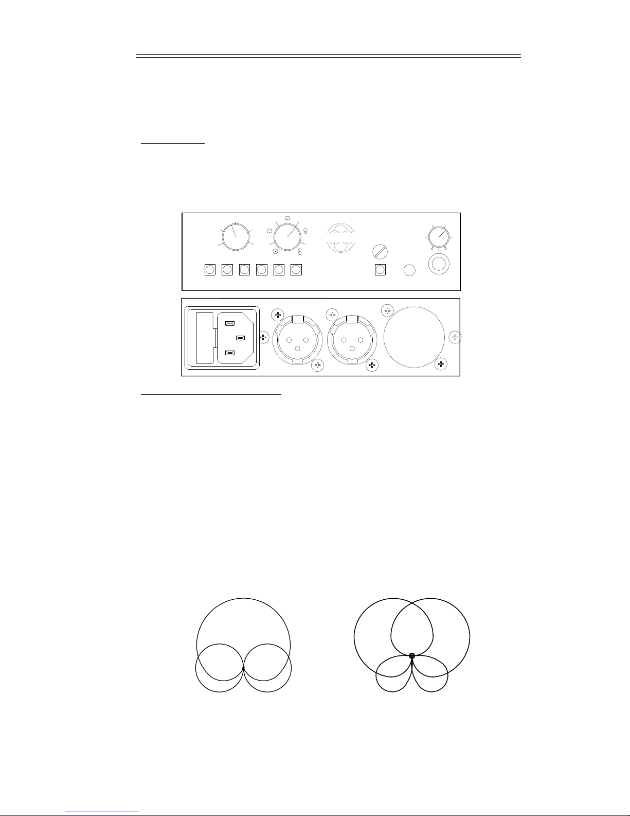
Quick Start
Getting Started
The ST250 microphone head is powered from the control box which is powered in one of three
ways - mains, phantom or battery. With mains and phantom, the unit is active as soon as power
is supplied, but with battery the BATTERY button needs to be depressed. When the control box
is powered up the red LED on its front panel illuminates. Before powering up ensure that the
multicore cable is firmly connected to both the microphone head and the control unit. The two
screw connectors ensure that the cable cannot come free. Next connect the control unit to your
desk/recorder by means of the two XLR sockets on the back. The output levels of the control
unit are such that you can connect to either hi-mic or line level inputs. However, when
connected to a microphone input ensure that your input gain controls are turned right down.
Connect power to the control box and switch on (red LED lights up). The unit will take up to
one minute to polarise the capsules, but may take up to 5 minutes to stabilise depending on
conditions. Your ST250 is now ready for action.
Initial Settings
The default setting for the ST250 is achieved with all of the six buttons at the bottom left of the
control unit out (a buttons function is active when the button is in). In the default condition you
have a side fire microphone with flat response, a peak signal level of 115dB and Left/Right
outputs from the controller.
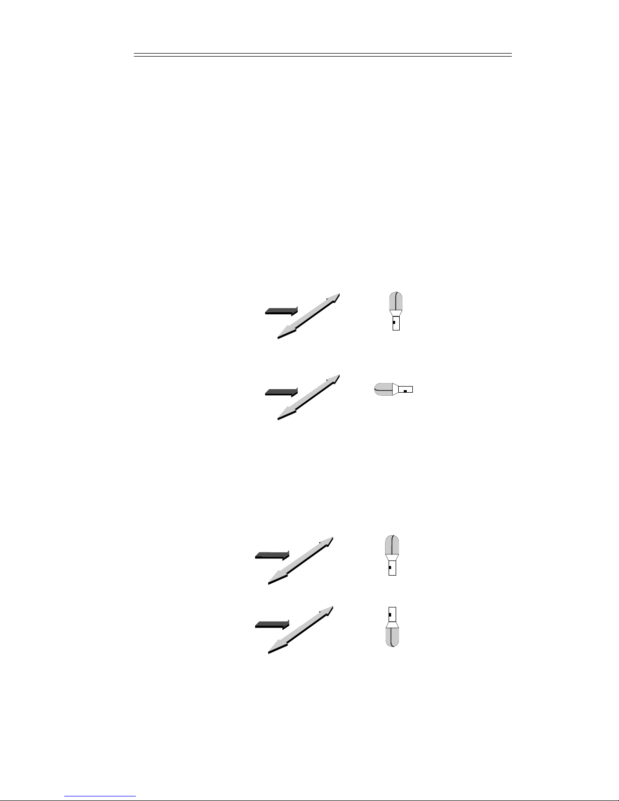
The effective operational position of the ST250 is determined by the settings of the END and
INV buttons. Use the label on the front of the microphone as a reference point.
Microphone Orientation

The SoundField ST250 Issue 1.5 User Guide
44
Other Functions
Buttons
BASS
when in, a bass roll off filter (120Hz, 2 pole) is added as the microphone signal enters the
control box.
ATTN
when in, puts a 20dB pad on the microphone, allowing a peak signal of 135 SPL.
M/S
when in, gives the separate M and S components at the outputs of the control box.
B
when in, gives the four B-format signals at the outputs of the control box. Refer to page 8 and
Appendix A for more detail on B-format.
BATTERY
when batteries are fitted, acts as an ON/OFF switch to conserve battery power. ON when pressed
in.
Miscellaneous
OVERLOAD
the POWER LED will flicker when overload is approached.
PHONES
Standard Stereo 6.3mm (1/4") jack output. Volume control located above socket. Monitors the
XY output at all times regardless of any other setting.
Width and Pattern Controls
It must be realised that the ST250 operates as a M/S microphone whether it is outputting M/S or
Left/Right. If you are not familiar with the concept of M/S, refer to the next section.
WIDTH
This controls the gain of the sideways facing (S) figure of eight component. The scaling of the
control is 0-10 (0-100%). When this control is fully rotated (100%) the S gain is equal to that of
the M gain.
PATTERN
This controls the polar response of the mid facing (M) component. It is continuously variable
from omni to figure-of-eight.
The relation between M/S and LEFT/RIGHT can be summed up as follows:
LEFT = M + S
RIGHT = M - S
Refer to the graph in the Appendix B for quick conversion between the M/S settings and their
LEFT/RIGHT equivalents.
The SoundField ST250 Issue 1.5 User Guide
5
Operation
Introduction
The ST250 is an M-S microphone and the two controls on the front panel allow independent
control of the middle and side signals. The pattern control will vary the M polar pattern of the
microphone from omni-directional through various sub-cardioids to cardioid and then through
the hyper-cardioids to figure-of-eight. No matter which pattern is selected the signal level for a
source at the front of the microphone is constant.This is the essential point of the design.
Width and Pattern Controls
The width control varies the level of the sideways figure of eight; at maximum the sensitivity is
the same as that of the M signal for a source to the front of the microphone. A given control
configuration implies a corresponding equivalent crossed pair of microphones.
By definition
Left = M + S
and Right = M - S.
The effective width of the stereo image can be adjusted from mono at one extreme to a very
wide stereo image equivalent to the image produced by two back-to-back cardioids with an
angle of 180 degrees between them when the width control is set to 10 and the pattern is set to
omni. The graph in Appendix B allows conversion between the M-S settings of the ST250 and
an equivalent crossed pair. The graph is given to allow comparisons only, in practice people will
use their ears. Adjust rear rejection with the pattern control. Adjust stereo image width with the
width control. The two are independent.
M/S STEREO
M
S
L/R STEREO
RIGHT
LEFT
010
2.5 7.5
5
Stereo Control
Unit
Battery Power Phones
PatternWidth
Bass Atten End Inv M/S B
SOUNDFIELD RESEARCH
50-60Hz 1A B=ZYB=WX ST250 Mic
(M)
Left Right
(S)
240V
Made in Englan
d
W
Z
Y
X
SOUNDFIELD
ST 250

66
M
-
+
M/S
LR
LR
LRLR
M
S
+S
+
--
M
M
-
+
FIGURE 3
M/S Switch
In its normal position L/R signals are sent from the L and R output sockets. Pushing the M/S
button will send M to the L connector and S to the R connector. Note that the microphone is
always an M-S microphone whatever this setting.
Figure 4 shows the equivalent L/R patterns when the M/S patterns are as indicated in Figure 3
above.
L / R
LR
LR
LRLR
Pattern set at 40% rotation
width at 4
Pattern at cardioid
width at 5
Pattern at omni
width at 10
Pattern at figure of eight
width at 10
2 Cardioids at 9002 Hypercardioids at 900
2 Figure of Eights at 9002 Cardioids at 1800
Figure 4
The SoundField ST250 Issue 1.5 User Guide
The SoundField ST250 Issue 1.5 User Guide
7
Microphone Positioning
As this microphone can be switched from vertical to end-fire and also inverted, it is important
for the user to identify the positioning of the microphone relative to the stereo image. The
SoundField logo has been placed on the microphone to identify the front in the vertical mode.
When used in the vertical or inverted position, the logo should be directed towards the sound
source. When used in the end-fire position the logo indicates the underside of the microphone.
Obviously, if the microphone is physically inverted and the INVert button is depressed, the
identifying mark will then represent the top of the microphone.
END Switch
By depressing the END button the ST250 can be switched from use in the vertical or upright
position to the end-fire position. In the end-fire mode the angle and polar pattern controls
operate in the same way as for the vertical mode. See Figure 5.
INVERT Switch
If the microphone itself must be physically positioned upside down, left and right outputs are
effectively reversed. The INVert switch on the ST250 Control Unit allows the user to maintain a
true configuration of the L - R channels by reversing the L - R channel outputs if depressed. See
Figure 6.
End Out Inv Out
End In Inv Out
Right
Left
SOURCE
Right
Left
SOURCE
EndFireMic
Side Fire Mic
End Out Inv Out
End Out Inv In
Right
Left
SOURCE
Right
Left
SOURCE
Inverted
Side Fire Mic
Side Fire Mic
The SoundField ST250 Issue 1.5 User Guide
888
B Switch
This switch allows the user to record B-format four channel sound via the special STCB cable.
These signals facilitate the complete post production of the sound (with control over both
response and position) after the recording has been made with a suitable B-format processor (eg
a SoundField control box). B-format can also be used to generate a surround sound recording.
The B-format [X W Y Z] signals are unbalanced and exit the control unit via pin 2 and 3 of each
three pin XLR output. The output impedance of each of these signals is 750R, thus a short cable
should be used.
Note also that to maintain compatibility with the MkIV and MkV SoundField microphone the W
or pressure signal is decreased by 3dB and these outputs are all in antiphase to the acoustic
signal.
ATTEN Switch
The attenuation switch is for use when recording very high signal levels. The button pads the
input of the microphone by 20dB to avoid distortion.The microphone will handle sound levels of
up to 115 SPL before the attenuator needs to be engaged.
BATTERY Switch
The above switches the batteries in circuit (housed in the control unit) for self-powering. Using
standard alkaline C cells, the expected operational life for the batteries is a minimum of 5 hours.
BASS Switch
This switch rolls off the bass response of the microphone from 120Hz (3dB down) to reduce
wind noise or unwanted low frequency ambient signals.
The bass roll off switch affects the bass frequencies of both the "M" and the "S" signals. It is
probably most needed when the microphone is used on close voice when a very directional
pattern is chosen.
Headphone Monitoring
Whether in L/R or M/S mode you can monitor the output signal from the control unit in L/R
format. This is intended as a checking device to ensure the system is working correctly and for
balancing the stereo image. It is not intended as a permanent monitoring facility, nor should it be
used as an output as the signal from the monitor has not been processed to the same specifica-
tions as the main outputs.
Continuous monitoring when battery or phantom powered will affect the performance of the
ST250 and, if using battery power, will reduce battery life and lower the headroom.
010
2.5 7.5
5
Stereo Control
Unit
Battery Power Phones
PatternWidth
Bass Atten End Inv M/S B
SOUNDFIELD RESEARCH
50-60Hz 1A B=ZYB=WX ST250 Mic
(M)
Left Right
(S)
240V
Made in Englan
d
W
Z
Y
X
SOUNDFIELD
ST 250
The SoundField ST250 Issue 1.5 User Guide
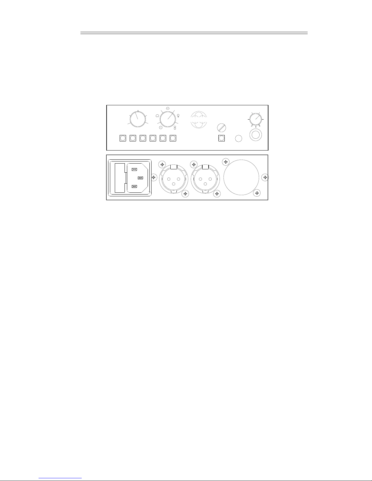
9
++
++
FRONT
Top View
Powering the ST250
Powering is from either 100v, 110v, 240v mains, 48v phantom power or batteries.
Mains Power
The microphone is supplied set to operate at the voltage of your local mains supply. Should you
wish to use the ST250 in a country where there is a different mains voltage, we recommend that
battery power is used. If this is not possible please contact your SoundField representative who
will explain how to change the operating voltage.
Phantom Power
The ST250 is designed to run on 48v +/- 5v phantom power systems.
However, 20mA of current is required and most boards will not supply this without a minor
modification. Phantom power is taken from both XLR connectors and 10mA per connector is
required. 25 volts is required to operate the unit. This implies that the phantom resistors must be
less than 3K9 per side (potential drop 5mA x 3900 = 20v) and to avoid an excessive load on the
signal these resistors should be greater than 3K3. The standard phantom power resistor of 6K8
will cause misoperation with typical symptoms being high noise and peculiar stereo imaging.
The unit is safe to operate on transformer phantom power supplies.
NOTE - problems may also arise if standard phantom power is fed to an
ST250 as it is being powered from the mains or battery. Once again, high
noise and peculiar imaging can result. We recommend either switching
off the phantom power or connecting the unit to a LINE level input. If this
is not practical, a small modification of the control box removes the
phantom power circuit and the mic is powered from the mains or
battery. Contact your SoundField representative for further details.
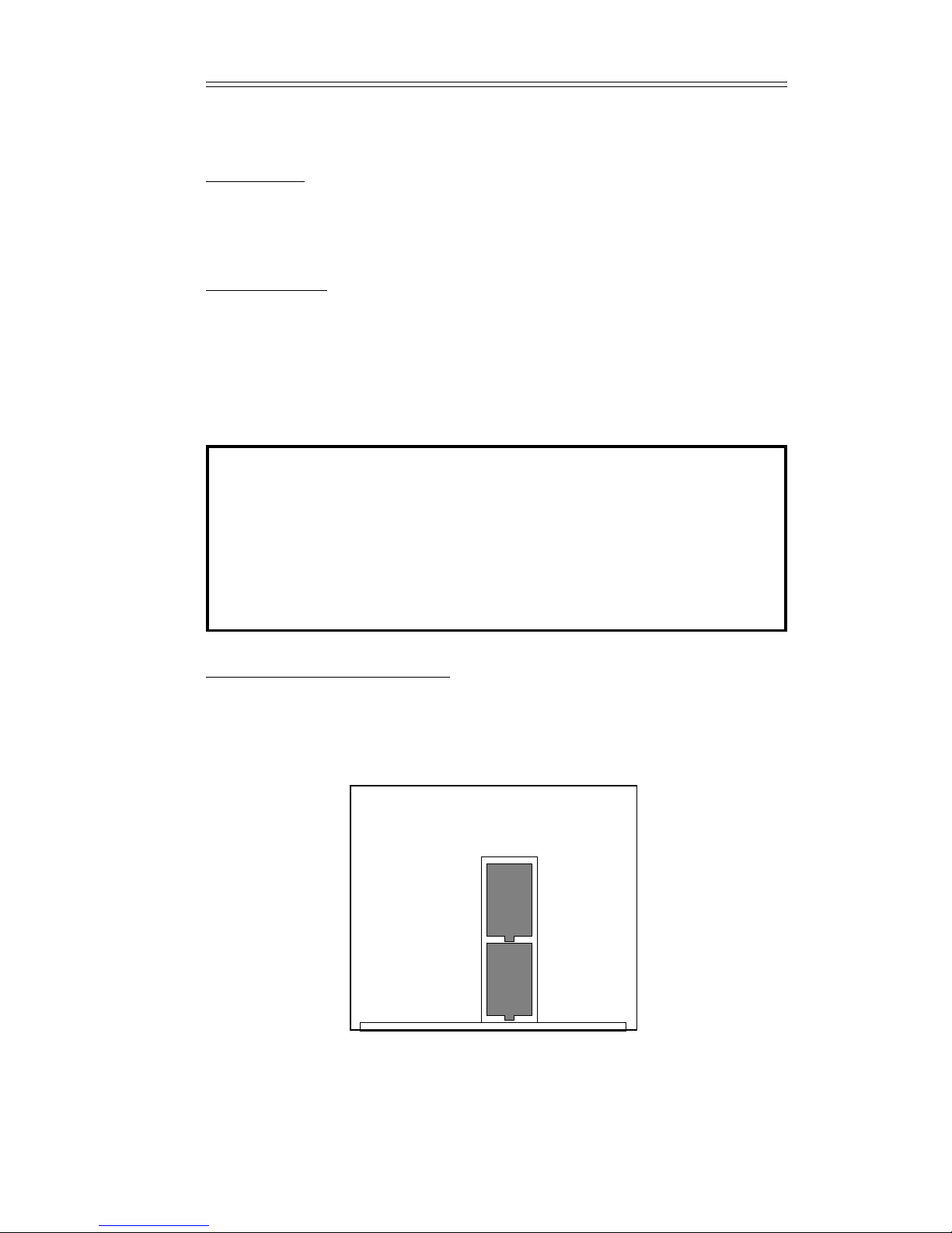
Battery Power and Replacement
The battery power supply is housed in the control unit. Unscrew the chrome knurled nut above
the battery switch and pull out the front panel to reveal access for 2 x "C" size battery cells. It is
recommended that alkaline (Duracell) type batteries are used. Be careful to ensure that the
batteries are placed with the positive end pointing towards the front panel. See Figure 8. Replace
the front panel and ensure the knurled screw is tight.

The SoundField ST250 Issue 1.5 User Guide
110
10
Specification ST250
Output levels are measured with a high impedance load
with 20dB attenuator
Front Sensitivity at 80SPL (fixed) -27dBV -47dBV
Maximum variation of M with pattern +/- 1.5dB
S sensitivity at 80dB SPL (maximum) -27dBV -47dBV
W output 80dB SPL -30dBV -50dBV
X,Y,Z output 80dB SPL -27dBV -47dBV
Frequency range +/- 2dB 20Hz - 20kHz
with bass cut 120Hz - 20kHz
Noise (M cardioid or omni) 17dB SPL A weighted
(anechoic measurement)
Maximum sound level 115 dB SPL 135 dB SPL
Powering:
a) Mains 240V/110V set by internal link.
b) Battery 2 alkaline C cells will power the unit for 5hrs
minimum.
c) Phantom powering from 48V+/- 5V current drawn 4x
5mA Impedance less than 3K9 per line.
Output two 3 pin XLR male connectors. Pin 2 has signal on it and pin 3 provides an equal
impedance connection to ground. It should be connected to a balanced input.
Output impedance 220R M/S A/B balanced.
B-format 750R unbalanced.
As a policy of continual improvement of products is pursued, specifications are subject
to change without notice.
Humidity and Condensation
Condensation which is caused by rapid changes in humidity and cold, damp conditions can be a
problem to ALL polarised capacitor microphones. Moisture from the atmosphere or from the
breath, if used close to the mouth, may condense on the capsules resulting in noise and reduced
signal. The ST250 microphone includes a heater in the capsule cluster to minimise this effect
and normal performance is restored when this moisture has completely evaporated. The heater is
only operative when the unit is powered from the mains. It is therefore advisable when the
microphone has been stored in a cold place, such as in a vehicle overnight, to bring the
microphone into a warm dry environment prior to use and full performance will be achieved
more quickly. It is also desirable to fit the foam windshield if the microphone is used at close
range, and to use an anti-pop screen at about 20cm distance.

The SoundField ST250 Issue 1.5 User Guide
11
Warranty
Limited Liability
SOUNDFIELD RESEARCH LTD., HEREIN AFTER KNOWN AS THE MANUFACTURER,
GUARANTEES THIS EQUIPMENT FROM DEFECTS IN MATERIAL AND WORKMAN-
SHIP UNDER NORMAL USE AND SERVICE FOR A PERIOD OF ONE YEAR. THIS
GUARANTEE EXTENDS TO THE ORIGINAL PURCHASER ONLY AND DOES NOT
APPLY TO FUSES OR ANY PRODUCT OR PARTS SUBJECTED TO MISUSE, NEGLECT,
ACCIDENT OR ABNORMAL CONDITIONS OF OPERATION. THE GUARANTEE BEGINS
ON THE DATE OF DELIVERY TO THE ACTUAL PURCHASER OR TO HIS AUTHORISED
AGENT OR CARRIER.
IN THE EVENT OF FAILURE OF A PRODUCT COVERED BY THIS GUARANTEE, THE
MANUFACTURER OR THEIR CERTIFIED REPRESENTATIVES WILL REPAIR AND
CALIBRATE EQUIPMENT RETURNED PREPAID TO AN AUTHORISED SERVICE
FACILITY WITHINìONE YEAR OF THE ORIGINAL PURCHASE AND PROVIDED THAT
THE GUARANTORS EXAMINATION DISCLOSES TO ITS SATISFACTION THAT THE
PRODUCT WAS DEFECTIVE, EQUIPMENT UNDER THIS GUARANTEE WILL BE
REPAIRED OR REPLACED WITHOUT CHARGE. ANY FAULT THAT HAS BEEN
CAUSED BY MISUSE, NEGLECT, ACCIDENT, ACT OF GOD, WAR OR CIVIL INSUR-
RECTION; ALTERATION OR REPAIR BY UNAUTHORISED PERSONAL; OPERATION
FROM AN INCORRECT POWER SOURCE OR ABNORMAL CONDITIONS OF OPERA-
TION, WILL NOT FALL UNDER THIS GUARANTEE. HOWEVER, AN ESTIMATE OF
THE COST OF THE REPAIR WORK WILL BE SUBMITTED BEFORE WORK IS
STARTED.
THE MANUFACTURER SHALL NOT BE RESPONSIBLE FOR ANY LOSS OR DAMAGE,
DIRECT OR CONSEQUENTIAL, RESULTING FROM MACHINE FAILURE OR THE
INABILITY OF THE PRODUCT TO PERFORM.
THE MANUFACTURER SHALL NOT BE RESPONSIBLE FOR ANY DAMAGE OR LOSS
DURING SHIPMENT TO AND FROM THE FACTORY OR ITS DESIGNATED SERVICE
FACILITY.
THIS GUARANTEE IS IN LIEU OF ALL OTHER GUARANTEES, EXPRESSED OR
IMPLIED, AND OF ANY OTHER LIABILITIES ON THE MANUFACTURERS PART.
THE MANUFACTURER DOES NOT AUTHORISE ANYONE TO MAKE ANY GUARAN-
TEE OR ASSUME ANY LIABILITY NOT STRICTLY IN ACCORDANCE WITH THE
ABOVE.
THE MANUFACTURER RESERVES THE RIGHT TO MAKE CHANGES OR IMPROVE-
MENT IN THE DESIGN AND CONSTRUCTION OF THIS UNIT WITHOUT OBLIGATION
TO MAKE SUCH CHANGES OR IMPROVEMENTS IN THE PURCHASERS UNIT.
ANY DISPUTE ARISING FROM THIS WARRANTY SHALL BE SUBJECT TO THE LAWS
OF ENGLAND.
What to do if a fault is found
If a fault develops in the unit, notify SoundField Research Ltd. or their nearest service facility
giving full details of the difficulty. On receipt of this information, service or shipping instruc-
tions will be forwarded to you. No equipment should be returned under the warranty without
prior consent from SoundField Research Ltd or their Authorised Representative.

The SoundField ST250 Issue 1.5 User Guide
12
Shipping Information
Authorised returns should be prepaid and must be insured. All SoundField products are packaged
in specially designed containers for the best possible protection. If the unit is returned the
original container should be used. If this is not possible, a new container can be obtained from
SoundField Research Ltd. please specify the model number when requesting a new container. If
the specially designed container is not used ensure that a suitable rigid container of adequate size
is used, wrap the instrument in paper and surround it with a good thickness of shock absorbing
material.
Claim for damage during transit
The instrument should be thoroughly inspected immediately upon delivery to the purchaser. If
the instrument is damaged in any way a claim should be filed with the carrier immediately. A
quotation to repair shipment damage can be obtained from SoundField Research Ltd. or their
Certified Representative. Final claims and negotiations with the carrier must be completed by
the customer.
Applications problems
SoundField Research Ltd. will be happy to answer all applications questions to enhance your use
of this equipment. Please address all correspondence to:
SoundField Research Ltd.
Charlotte Street Business Centre
Charlotte Street
Wakefield
West Yorkshire
WF 1 UH
ENGLAND

13
The SoundField ST250 Issue 1.5 User Guide
Quality Assurance and Service Policy
Over the years SoundField products have gained an enviable reputation for their quality of
design, performance and reliability, however, in the unlikely event that problems are
encountered with this unit, please contact SoundField Service at the appropriate address below
or alternatively inform one of our world wide network of distributors who will be able ìto assist
with any of your queries.
SoundField Research Ltd.
Charlotte Street Business Centre
Charlotte Street
Wakefield
West Yorkshire
WF1 1UH
ENGLAND
All SoundField products are sold subject to our General Conditions of Sale and the purchaser
should note that the equipment is not being sold to him to meet his individual requirements and
it is therefore the buyers responsibility to ensure that the purposes and functions of the
equipment meet his requirements prior to purchase. However, we would non-the-less be grateful
to receive any constructive criticism or ideas for additional features which you feel might
enhance the usefulness of our product in the studio environment.

The SoundField ST250 Issue 1.5 User Guide
14
Appendix A
Theory of Operation
The ST250 produces truly coincident stereo signals, it achieves this using the much acclaimed
SoundField technology and this next section describes in some detail how this technology has
been developed for use in the ST250.
The microphone head contains four sub-cardioid capsules set in a regular tetrahedron. The
capsule signals are in fact added and/or subtracted to provide a set of four signals known as B-
Format, as described below.
Closer examination of the capsule array shows that the Left Front and Right Back capsules are
back to back, but tilted symmetrically from the vertical. If the signals from these 2 capsules are
subtracted then the two sub-cardioid capsules produce a horizontal figure-of-eight pattern with
its axis along the line left front to right back.
Similarly, Right Front and Left Back are tilted symmetrically downwards and when subtracted
produce a horizontal figure-of-eight pattern with its axis along that line. The two figure-of-eight
patterns are added with Left Front and Right Front in phase to produce a figure-of-eight pattern
whose axis lies front/back and this is termed the X component of the B Format signal.
Subtraction of the 2 diagonal figure-of-eight patterns produces a figure-of-eight pattern whose
axis lies along the left/right axis and this is the Y component (positive left).
Further combination of pairs produce 2 figure-of-eight patterns at 45° to a vertical axis resulting
in a final Z component whose axis lies along the up/down axis (positive up).
The remaining B-Format component, W, is an omni-directional pattern produced by summing
the four capsule outputs in phase.
Thus the B-Format components are:
W=LF+RB+RF+LB
X=LF-RB+RF-LB
Y= LF- RB- RF+ LB
Z=LF+RB- RF- LB
The B Format signal can therefore represent sound from any point in space by 3 directional co-
ordinates X, Y & Z, and the pressure component W.
Note, that each capsule makes an equal contribution to each of the four B-Format signals and it
is this factor and the symmetry of the array which causes a certain amount of cancellation of
capsule errors to produce performance characteristics not possible except with SoundField
technology.
Moreover, compensation is applied to the resulting signals in amplitude and phase, to effectively
bring the four B-Format signals to an origin at the centre of the cluster. This coincidence of the
signal components has remarkable effects on the accuracy of a synthesised stereo microphone
which can be set up from combinations of the B-
Format signals and contrasts vividly with other approaches where coincidence is often lost at
frequencies as low as 1kHz (if there at all!). How this is done will now be described:
If a microphone is required to be omni-directional then only the W component is used. If a
forward facing figure-of-eight is required the X component is used. An end-fire figure-of-eight
would be represented by the Z component.

The SoundField ST250 Issue 1.5 User Guide
15
X
X
XY
Y
22
If a cardioid is required facing forward, then the sum of W and X produces this, (although in
standard B-Format X, Y & Z are enhanced 3db for similar programme levels to W).
A cardioid is therefore actually W +
If two cardioids facing left-front and right-front are required then the transverse figure-of-eight
component Y (like S in M/S format), is introduced, positively for left and negatively for right as
follows:
Left W + +
Right W + -
The further reduction in level of the X signal by 3dB allows for the introduction of the Y signal
at a similar level to produce a pressure gradient signal of the same level
to that for mono to produce cardioid patterns.
It becomes obvious at this point how the B-Format components may be combined and
manipulated to achieve desired effects. For example, trading X for Y and vice versa will alter the
width of the stereo pick-up whilst trading the X-Y combination for W and vice versa will alter
the patterns from omni-directional through all the cardioids to figure-of-eight.
Controls are provided to achieve these variations. Moreover, by simply reversing Y, the
microphone may be suspended upside down, instead of being placed vertically on a stand, and
the signals remain correct. What is more important, is that Z and Y may be used instead of X
and Y, and all the aforementioned features may be achieved with the microphone in an end-fire
mode.
This is particularly valuable in TV work on a boom where the microphone can point at the
subject. Further examination reveals that since it is becoming extremely popular to work in the
M/S format, it is ìprobably better to introduce other controls rather than patterns and stereo
angle. There can be a variation of the M pattern by varying the ratio of W and X and the stereo
width by simply varying the amplitude of Y. The combinations are clearly endless and the
choices actually made have been determined after considerable discussions with recording
engineers from many areas of the audio industry.
22
2
2

The SoundField ST250 Issue 1.5 User Guide
16
F
igure of 8
H
ypercardioid
C
ardioid
M
Pattern
O
mni
SGain
Width
127˚
53˚ 90˚
c
d
b
a
S
ub-cardioid
1
.75
.5
.25
0
0 .25 .5 .75 1
0459013518
0
Appendix B
Converting Between M/S and L/R
alocus of cardioids
blocus of 135° hyper cardioid
clocus of 120° hyper cardioid
dlocus of figure of eights
The three other angled lines are loci of the nominated angles between synthesised L/R pairs.
Example
If a pair of cardioids with an angle of 90° between them is required, look at the intersection of
the 90° line and the cardioid locus. This corresponds to an S Gain of about 40% and a pattern at
slightly below the cardioid setting.

The SoundField ST250 Issue 1.5 User Guide
17
Appendix C
ST250 Microphone Shockmount Assembly Instructions
List of Parts
1 x Geodesic Suspension Cradle
2 x Elastic Loops
1 x ST250 Microphone Holder
1 x Stand Mounting Knuckle Joint - 2 pieces, slotted nut and bolt
1 x Allen Screw - 4mm hexagonal head
2 x Knurled Head Screw (Fischer Boom)
Stand Mounting
1Fit the holder into the cradle (Figure 1). The top four hooks on the holder
should clip onto one elastic loop and the bottom four onto the other. See
Figure 4 for position.
2Adjust the tension of the elastics so that the holder is held equidistant from
the sides of the cradle.
3Undo the slotted nut and bolt holding the knuckle (Figure ì3) together and
remove, allowing the two pieces of the knuckle to separate. This will provide
access to the head of the Allen screw.
4With a 4mm hexagonal screwdriver, fix knuckle to cradle by screwing Allen
screw into one of the two threaded holes on the cradle.
5Reassemble the removed section of the knuckle and tighten nut and bolt.
6Unclip the lugs. Fit the microphone as described below.
Rycote Mounting
Rycote manufacture a special ST250 system for special applications. This has been
designed to work in conjunction with the ST250 microphone holder (2).
1Fit the holder into the Rycote suspension. Each elastic loop on the Rycote
should pass around two adjacent fixing hooks on the holder. For ease of use,
put the securing lugs of the holder uppermost.
2Unclip the lugs. Fit the microphone as described below.
Fixing Microphone in Holder
1Relax the holder (Figure 2) by compressing the large and small ringsand
unclipping the securing lugs.
2Insert the ST250 microphone and refasten the lugs so that the larger end of
the microphone clamps just at the base of the windshield. Remember to take
into account the orientation of the microphone (refer to the ST250 user
manual for details).
3Screw the microphone cable onto the base of microphone
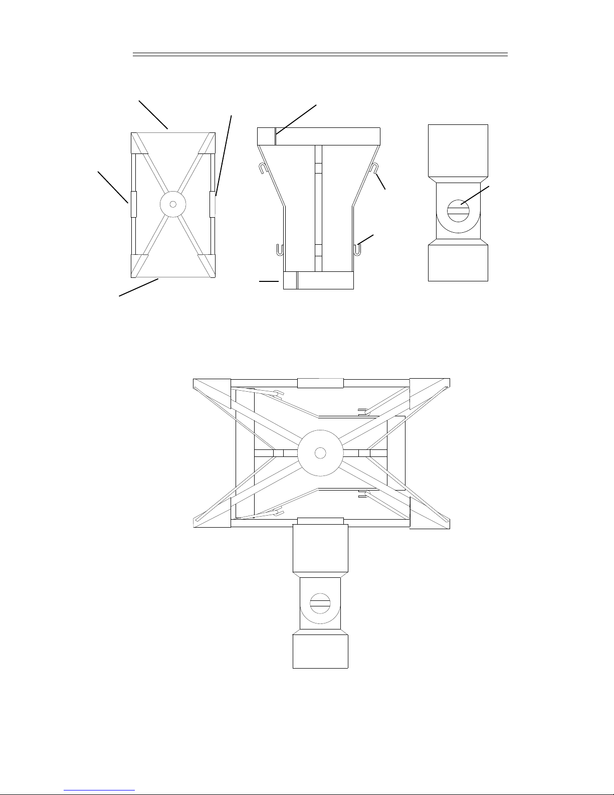
FIGURE 4 : ASSEMBLED SUSPENSION SYSTEM
18
TOP HOOKS
LUGS
LUGSTHREADED
HOLE
ELASTIC
THREADED
HOLE
ELASTIC
Fig 1 : Cradle Fig 2 : Holder Fig 3 : Knuckle
BOTTOM
HOOKS
SLOTTED NUT
AND BOLT
The SoundField ST250 Issue 1.5 User Guide
Other Soundfield Microphone manuals


Popular Microphone manuals by other brands


Sennheiser
Sennheiser SL Ceiling Mic Mounting instructions

Marshall Electronics
Marshall Electronics Orchid OR-434 operating instructions

Audio Technica
Audio Technica UniLine U853RU user manual

Devine
Devine M-Mic PRO USB W user manual

Paso Sound Products
Paso Sound Products RDU216 Installation manual and operating instructions

Wharfedale Pro
Wharfedale Pro USX 800 user manual


